Table of Contents
Advertisement
Quick Links
Advertisement
Table of Contents

Related Manuals for micro-trak MT-3000


Summary of Contents for micro-trak MT-3000
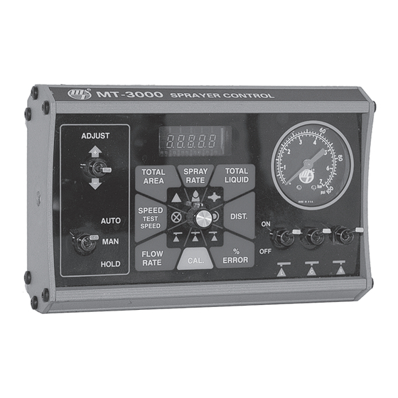
- Page 1 M T - 3 0 0 0 Automatic Sprayer Control System REFERENCE MANUAL...
- Page 2 The MT-3000™ has been designed for easy installation and op er a tion. How ev er, since each in stal la tion will vary depending on your equipment, please take time to fa mil iar ize yourself with this manual and the actual components before beginning.
-
Page 3: Warranty
* Some limitations apply. See warranty statement for details. At Micro-Trak Systems, we believe a product that delivers quality and performance at a low cost is what is needed to help today’s operator and the operator of the future compete in the world mar ket. -
Page 4: Table Of Contents
Table of Contents Warranty...................................... 3 Table of Contents ..................................4 Component Parts and Assembly Hardware ......................... 5 MT-3000 System Diagram ............................... 6 General Description .................................. 7 Installation .....................................7-18 Optional Equipment ....................................7 Pre-Installation ......................................8 General Installation ....................................9 Mounting the Display Console ................................9 Electrical Installation .................................... -
Page 5: Component Parts And Assembly Hardware
Component Parts and Assembly Hardware Automatic Sprayer Control System Before beginning installation, check the carton contents for the following items: REFERENCE MANUAL Reference Manual P/N 12245 MT-3000 Console Console Mount Bracket Console Mount Knobs P/N 10365 P/N 10422 P/N 10423... -
Page 6: Mt-3000 System Diagram
MT-3000 System Diagram... -
Page 7: General Description
19 - 198 GPM (72 - 750 The MT-3000 is designed to operate with sprayers pumping lpm) range. non-abrasive liquids. The operator may select any one of Controlling seven (7) monitored functions. -
Page 8: Pre-Installation
Installation (cont.) Tools Needed to Install MT-3000 Pre-Installation • Screwdrivers • Pliers • Set of Wrenches • Wire Cutter • Electric Drill and Bits • Hammer • Center Punch • 12-Volt Test Light • Measuring Tape • Hack Saw • Teflon Joint Tape •... -
Page 9: General Installation
5’, 10’, 15’ and 20’ extensions are available. will make a properly designed system perform far better than any manually operated system. The MT-3000 can not make TIPS ARE THE KEY a poorly plumbed system perform properly and may cause a Many sprayers today are operating with wrong size, worn, marginal system not to operate at all. -
Page 10: Electrical Installation
(cont.) 12 VDC Electrical Installation Illustration 3 +12VDC MT-3000 Your MT-3000 will work on either positive or negative ORANGE/BLUE ground 12 volt systems. Route wires away from hot engine ORANGE components, moving parts and high tension (spark plugs) wires. Cut wires to proper length, crimping on appropriate... -
Page 11: Mounting Bracket
Installation Drive Shaft Installation (cont.) Mounting Bracket Use this installation on pickups, 4-wheel-drive tractors, planters, etc. Cut and bend as required. Rigidly mount using ¼” bolts, self- Locate sensor mount bracket on frame near transmission, tapping screws or by welding. NOTE: Always disconnect transfer case or hanger bearing, where drive shaft has console before welding on equipment. -
Page 12: Trak-Star Installation
Installation (cont.) Trak-Star Ultrasonic Speed Sensor GENERAL MOUNTING INFORMATION DETERMINING REQUIRED CLEARANCE Trak-Star must be mounted parallel to the ground. When selecting a mounting location for the sensor, you must The ultrasonic horn is preset for the proper angle of first ensure that the path of the signal will not be obstructed reflection. - Page 13 SPLIT RING Trak-Star is equipped with mounting channels on all four (4) LOCKWASHER sides. When possible the preferred method of mounting is to suspend the unit from the top channel or support it vertically FLAT WASHER from the bottom channel. In some cases fabricating a RING TERMINALS ADAPTER CABLE MOUNTING...
- Page 14 The blue wire on the Trak-Star cable and of high heat or abrasion. Secure cable along entire MT-3000/5000 adapter cable must be attached to the length with cable ties. DO NOT plug cables together frame making sure there is good metal to metal contact.
- Page 15 Installation EXAMPLE: (cont.) NORMAL LEVEL MOUNTING POSITION Trak-Star Ultrasonic Speed Sensor (cont.) DISPLAY READS Calibration Adjustments If under actual field conditions you find that your speed measurements (or distance) is consistently off, as determined SPEED by another independent measurement, you can fine-tune the system by following the speed calibration instructions for your particular monitor/controller and increasing or decreasing the speed calibration value by a small amount...
-
Page 16: Plumbing
Installation For pumps rated above 50 GPM (190 lpm), use 1½” (cont.) suction line and 1¼” servo valve return line. Plumb Plumbing - General return line into pump inlet or back to tank (not agitation). Line must have unrestricted flow. Refer to system diagram on page 6 for component Boom having flow greater than 5 GPM (19 lpm) should locations. - Page 17 BOOST ADJUST SERVO AND THROTTLE VALVE WITHOUT BOOST SOLENOID WARNING: Do not use the MT-3000 pressure gauge for toxic chemicals or materials in compatible with nylon, THROTTLE SERVO FROM PUMP EPDM, brass, tin/lead solder or phosphor bronze (such as...
- Page 18 Installation NOTE: If you are using electric boom solenoids, you may (cont.) have to install a light bulb or some other 12 volt load in Servo, Throttling & Boost Valves (cont.) place of the solenoids to get the monitor to acknowledge boom widths and count area.
-
Page 19: Calibration
It has been factory preset to 2.00 GPM (7.5 lpm), the minimum recommended flow Calibration is simply a procedure that adapts the MT-3000 rate for the FM750 GFN flowmeter when used console to your particular equipment. There are two types with the MT-3400. -
Page 20: Auto Calibration
Calibration (cont.) Auto Calibration DISTANCE/SPEED FLOWMETER This calibration method automatically sets the distance This calibration method automatically sets the flowmeter calibration value while you adjust the distance. Before calibration value while you adjust the ‘TOTAL LIQUID”. proceeding, make sure your equipment and ground conditions Stop vehicle. -
Page 21: Pre-Field System Checkout
NOTE: If throttle valve is more than two thirds closed, open and desired speed range will allow the MT-3000 to control RANGE ADJUST slightly and readjust THROTTLE valve. the application rate you have selected. -
Page 22: Operation
Can be used to monitor how well Distance and area will not count, spray booms will not the MT-3000 is controlling flow. An error operate and pressure cannot be changed with the “+/-” of 10% or less is generally considered switch. - Page 23 : While the pressure gauge itself has change applications rates by flipping the “+/-” toggle switch. no bearing on the operation of the MT-3000, pressure is Each time you flip to “-”, the Target Rate will decrease by the very important and should not be overlooked. Make sure DELTA amount.
-
Page 24: Troubleshooting
Problem” and identify the component at fault. The right for assistance. Many times you can locate and correct the side of the page shows the component most likely causing problem on you own. MT-3000 Troubleshooting Flow Chart Overload on START Accessory... - Page 25 Troubleshooting (cont.) General (cont.) MT-3000 Troubleshooting Flow Chart Continued from Previous Page Re-calibrate and Exit Properly Does Console Was Cal. Exited Remember Console Properly? Cal. Numbers Does Console Remember Console Totals? Turn to speed and Does Does Speed Console Console...
- Page 26 Troubleshooting (cont.) General (cont.) MT-3000 Troubleshooting Flow Chart Continued from Previous Page Console Unplug Remote Does Distance Is Master Does Distance Run/Hold from in Hold? Count? Count in Hold? Main Harness Is Remote Set Remote Does Distance Set Remote Run/Hold...
- Page 27 Troubleshooting (cont.) General (cont.) MT-3000 Troubleshooting Flow Chart Breaker Console Continued from Previous Page Harness Are Boom Master in MAN. Do Booms Power at Solenoid Solenoids Remote in RUN Turn On? Solenoid Wires? Valve Installed (Jumper Cover Installed) Console Do Boom Switches...
- Page 28 Troubleshooting (cont.) General (cont.) MT-3000 Troubleshooting Flow Chart Continued from Previous Page Does Spray Does Flow Does Speed Does Area Console Rate Register? Register? Count? Rate Register? Go to Box Go to Box Go to Box Number 19 Number 7...
- Page 29 SHOULD LIGHT harness on a vehicle with a known working MT-3000 system or install it on an EPOP (electronic point of purchase) display stand. NEVER try to direct wire the connector of an MT-3000 console. POWER FROM PIN 13 TO PIN...
- Page 30 Plumbing is a very important factor in the proper performance Connect an ohmmeter or continuity tester to the leads of the of the MT-3000 system. The following chart will help you Remote Run/Hold Switch or sensor). With the Remote Switch...
- Page 31 Troubleshooting (cont.) Plumbing Troubleshooting Chart SYMPTOM POSSIBLE CAUSE POSSIBLE SO LU TION Loses pressure in MAN Pump Air-lock Clean strainer Larger hoses Little or no pressure adjustment in MAN Too much restriction in servo loop Larger hoses and fittings No sharp bends Pressure won’t go high enough in MAN Pump starved or too small Larger hoses Too much agitation...
-
Page 32: Plumbing Guidelines
12) show the plumbing configuration that works best with EXAMPLE the MT-3000 Sprayer Controller. This section will explain Let’s say our example sprayer has a 300-gallon tank with the purpose of each component, list some problems it can a Spraying Systems 6290 SC-8 Jet Agitator. - Page 33 Slowly bring pump up to operating RPM boost valve opened. Provided the boost adjust has been (make sure pressure does not go too high). Put the MT-3000 properly set, the servo does not have to compensate for in MAN and turn boom on.
-
Page 34: Care And Maintenance
Care and Maintenance ASSEMBLING THE FLOWMETER Stainless steel meters use a Teflon gasket. Sealants are General normally not required. Plastic meters use an o-ring (Quad- ring). Apply a small amount of silicon grease for lubrication. CABLES Gaskets and o-rings may be reused several times but Always use dust caps. -
Page 35: Useful Information
Useful Information General UNITS OF MEASURE VERIFYING COUNTS 1 foot = 12 inches 1 mile = 5280 feet Temporarily enter a flowmeter calibration of 10.0. Clear TOTAL LIQUID to zero. Temporarily disconnect flow sensor 1 inch = 2.54 cm 1 acre = 43560 sf 1 meter = 100 cm 1 hectare = 10,000 sq. -
Page 36: Specification And Replacement Parts
CONSOLE (P/N 10365 SPARE PARTS AND ACCESSORIES 12 volt positive or negative ground with built-in switching The following parts are available from you local Micro-Trak regulator. High intensity vacuum florescent display. Current dealer or directly from the factory. Prices and specifications draw is less than 1 amp without solenoids. -
Page 37: Anhydrous Ammonia
Anhydrous Ammonia General Description in the OFF position. All plumbing components have a certain amount of restriction. These restrictions cause a pressure drop which allows some Pre-Installation of the anhydrous ammonia to partially vaporize as it flows from the tank. The amount and density of the vapor can Make certain that your application is within the capabilities vary greatly, therefore vapor cannot be accurately measured. - Page 38 Anhydrous Ammonia (cont.) TO MANIFOLD Installation VAPOR TUBES WARNING Always follow standard safety procedures and use proper safety equipment when working on anhydrous ammonia equipment Before working on plumbing: BREAK-AWAY COUPLER • Disconnect nurse tank. • Remove all ammonia from system •...
- Page 39 Allow extra hose to minimize kinking at hinge points. Cut to length NOTE: NEVER USE THE MT-3000 CONSOLE PRESSURE (make sure enough hose is left for other side) and attach the GAUGE WITH ANHYDROUS AMMONIA.
- Page 40 The shut-off (electrical ball) valve is controlled by the boom switch on the MT-3000 and by a separate switch in the harness on the MT-5000 (left boom switch must be on). BLUE...
- Page 41 Enter the applicator width into the console’s left boom metering vapor, you will notice extremely low manifold calibration position. For MT-3000 operation, use the left pressure. Change tanks before NH 3 level is low enough to boom switch to control the electric shut-off valve. These cause these problems.
- Page 42 Anhydrous Ammonia (cont.) Troubleshooting Refer to the console operator’s manual for most CAUSE troubleshooting procedures. Excessive pressure drop in plumbing from tank to NH3500 system or plugged vapor lines. ELECTRIC SHUT-OFF DOES NOT OPERATE REMEDY 1 Remove Hold Cutout Module and plug harness directly Optimizing all plumbing and keep vapor tubes clean.
- Page 43 Anhydrous Ammonia seal. Be careful not to get compound inside flowmeter or (cont.) turbine will stall. Carefully put other flowmeter housing Flowmeter Cleaning Procedure (sensor half) in place. Position the housing so that the two square lugs are lined up with each other. Drop all three bolts NOTE: Cleaning the flowmeter does not require loosening into holes.
- Page 44 M A N U F A C T U R E D I N U . S . A . B Y : 1305 Stadium Road, Mankato, MN 56001-5355 Toll Free: (800) 328-9613 (507) 257-3600 www.micro-trak.com • trakmail@micro-trak.com © 2007 Micro-Trak Systems, Inc. • Printed in U.S.A. P/N 12245 Copyright 2007 Rev. 4...
Need help?
Do you have a question about the MT-3000 and is the answer not in the manual?
Questions and answers
How to Calibrate wheel sensor on mt 3000
To calibrate the wheel sensor on the Micro-Trak MT-3000:
1. Disconnect any Trak-Star Ultrasonic Speed Sensor or radar from the console before calibration.
2. Perform AUTO CALIBRATION - DISTANCE/SPEED as described on page 25 of the manual.
3. The calibration value represents the distance traveled between magnets.
4. Ensure the value falls within the range of 1.00 (.001) to 192.0 (65.535).
5. Stand still during calibration to avoid false pulses from the sensor.
This ensures accurate distance and speed readings.
This answer is automatically generated