Table of Contents
Advertisement
Quick Links
Advertisement
Table of Contents

Subscribe to Our Youtube Channel
Related Manuals for micro-trak SprayMate XRS


Summary of Contents for micro-trak SprayMate XRS
- Page 2 Please read the manual carefully and follow the instructions as they apply to your usage. If you do encounter a problem that cannot be corrected by reviewing this manual, consult your dealer or distributor, or contact a Micro-Trak® technician for assistance. U.S. or Canada: Toll-free (800) 328-9613 or (507) 257-3600 Fax: 507-257-3001 www.micro-trak.com •...
- Page 3 Eagle Lake, MN 56024 At Micro-Trak® Systems, we believe a product that delivers quality and performance at a reasonable cost is what is needed to help today’s operator and the operator of the future compete in the world mar ket.
-
Page 4: Table Of Contents
Table of Contents ® Micro-Trak Warranty Table of Contents Component Parts and Hardware System Overview Wiring Diagram Wiring Details Installation Function Summary Calibration Operating Modes & Inline/Bypass Special Calibration Operation Pre-Field Sys tem Checkout Troubleshooting Appendices Appendix A - Fine Tuning Speed/Distance Calibration Val ue Appendix B - Fine Tuning Flowmeter Calibration Value Appendix C - “Quick Start”... -
Page 5: Component Parts And Hardware
Component Parts and Hardware AUTO SprayMate XRS Console Reference Manual Power Switch Kit Run/Hold Switch Kit P/N 19955 P/N 19959 P/N 21779 P/N 21778 Branch Harness Power Cable P/N 19958 P/N 14315-C Console Quick Mount Kit 5’ 16-pin Extension Cable 14”... -
Page 6: System Overview
System Overview... -
Page 7: Wiring Diagram
Wiring Diagram... -
Page 8: Wiring Details
Wiring Details SprayMate XRS Branch Harness P/N 19958 Overall Length: 15’ Branch Lengths: 3’ (With 2’ Pressure Sections (2) Sensor Adapter - 3-pin PN 19286) Weather-Pack Main Power Pressure Connection 2-pin 3-pin 16-pin Weather-Pack Metri-Pack 150 GT150/280 Multifunction Flow &... -
Page 9: Installation
This section explains how to connect the Spraymate XRS controller to a 12VDC power connection and wiring information about section shut-off valve connections. The Spraymate XRS controller must be connected to a 12VDC negative ground electrical system. -
Page 10: Function Summary
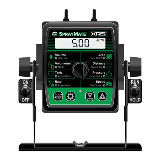
SprayMate XRS Console Func tion Summary The SprayMate XRS features a large, easy-to-read liquid crystal display, easy-to-use rotary dial and lighted panel for night use. The console also includes section switches, an audible alarm, and a serial port. VOLUME (1) (2) (3): AREA: Displays Keeps a running count... -
Page 11: Calibration
Calibration Before operating the SprayMate™ XRS, it is necessary to calibrate it for the intended operation. The first step is choosing intended UNITS (English or Metric) in Special Calibration, page 14 - this will also load default values. CALIBRATION STEPS: 1. - Page 12 This position calibrates the system to the speed sensor. The Choose between Vineyard and Orchard Modes . See SprayMate XRS system is designed to read distance input as Operating Modes - pg. 13. Distance per Unit. Default value is .189 for Micro-Trak Astro Vineyard Mode: GPS sensor.
- Page 13 Operating Modes Vineyard Mode: Orchard Mode: Sections: Sections: Sections are assigned consecutively left to right, as shown. Row Width is defined as the active width as illustrated Each section has individually assignable row width. below. If both sections are on, the Row Width is used as the active width.
-
Page 14: Special Calibration
Special Calibration The UNITS position must be set before changing any other Calibration or Special Calibration settings. These settings enable or disable other setting options to adjust applicable parameters: • UNITS: determines which unit of measurement is used • OUTPUT TYPE - PWM or STD: defines electronic drive signal for the control valve •... - Page 15 Location: PAGE 1 - RATE Description: This setting is NOT used in this version of the Description: Enables “Quick Start - Speed” function and SprayMate XRS. Do Not Adjust. Default: Closed defines the intended simulated speed in MPH (km/H). See Appendix C for details. Setting to 0 (Off ) will disable the function.
- Page 16 Description: Enables the use of three-way Valves with Default: 0 the SprayMate XRS system. This setting changes the PRESSURE ALARM LOW internal calculations for section totals so that flow in return lines to the tank (or to hydraulic system) is not Location: PAGE 2 - DISTANCE included when sections are turned off.
- Page 17 Special Calibration Settings - Page 3 Setting Locations Page Page 1 2 3 4 MINIMUM PRESSURE PWM FREQUENCY FIXED MINIMUM FLOW MAXIMUM PULSE WIDTH PROPORTIONAL MINIMUM FLOW MINIMUM PULSE WIDTH RATE ALARM THRESHOLD — MINIMUM PRESSURE PWM FREQUENCY - PWM ONLY Location: PAGE 3 - VOLUME Location: PAGE 3 - AREA Description: When using pressure based control, this...
- Page 18 Default setting this function is Master. when connecting a 3rd party mapping device to the 1. OFF = Always off SprayMate XRS system for automatic section control. 2. ON = Always on Default: 12v 3. RELIEF VALVE = On in Hold 4.
- Page 19 Special Calibration Default Settings & Change Notes Special Calibration - Page 1 Your Setting Default Default Your Setting TANK FILL LEVEL UNITS TANK ALARM LEVEL CONTROL SPEED OUTPUT TYPE: START SPEED TIME PWM or STD START SPEED HOLD INPUT POLARITY Special Calibration - Page 2 MANUAL ENABLE PRESSURE OFFSET...
-
Page 20: Operation
Operation Make sure your system is properly calibrated before beginning to apply product. We also recommend completion of the Pre- Field System Checkout described on page 21 prior to beginning any operations. Automatic Operation This mode sets and maintains the Target Rate (GPA) - the system compensates for speed changes or section switching. 1. -
Page 21: Pre-Field Sys Tem Checkout
Pre-Field Sys tem Checkout Before beginning actual spraying, perform the following “Pre-Field” procedure to ensure that your valve settings, nozzle selection and desired speed range will allow the SprayMate™ XRS to provide the required application control. This procedure should be repeated for each new nozzle se lec tion and/or application rate. (Most nozzles will maintain an adequate spray pattern over a maximum speed range of two to one. -
Page 22: Troubleshooting
If the meter CONSOLE. Your system is protected by a warranty, and has been used for some time, wear may have changed the Micro-Trak® will gladly correct any defect. Flow Cal value. See Fine-Tuning Flowmeter Calibration in Appendix D. - Page 23 12VDC to operate. Also, the Hall- assess it on a Micro-Trak® demonstration dis play. effect sen sor re quires al ter nat ing magnetic po lar i ties in or der HARNESS to switch.
- Page 24 Troubleshooting (cont.) Checking Console Inputs CONSOLE INPUTS FLOWMETER Shaking the Flowmeter end to end should pro duce a “rattling” If there is no response from any of the following tests, refer to sound (shaft end play). Blowing in the meter from either end the main wiring diagram to locate the next connector in line should spin the turbine freely.
- Page 25 Plumbing Troubleshooting Chart SYMPTOM POSSIBLE CAUSE POSSIBLE SOLUTION System loses pressure in MANUAL Pump Air-lock • Clean strainer • Install larger hoses Insufficient pressure adjustment in Too much flow restriction in servo loop • Install larger hoses and fittings MANUAL •...
-
Page 26: Appendices
Appendices... -
Page 27: Appendix A - Fine Tuning Speed/Distance Calibration Val Ue
Appendix A - Fine Tuning Speed/Distance Calibration Val ue This procedure is used to verify the Speed/Distance 4. With the rotary dial still at DISTANCE (SPEED CAL), press calibration. In order to achieve accurate measurements, and hold the button for one second. Once the con sole each step in this fine tuning procedure should be is in calibration mode, the speed calibration value will performed as precisely as possible. -
Page 28: Appendix B - Fine Tuning Flowmeter Calibration Value
Appendix B - Fine Tuning Flowmeter Calibration Value This procedure is used to verify and fine-tune the flowmeter With the console still in the VOLUME position, enter calibration. Every flowmeter is calibrated with water at the calibration, hold the button until the red warning factory and stamped with a calibration val ue. -
Page 29: Appendix C - "Quick Start" Function
Appendix C - “Quick Start” Function Quick Start can be enabled for use in Automatic operating mode. See Special Calibration section to enable/adjust the parameters. Quick Start - SPEED Provides the system a temporary simulated Speed whenever the system goes from HOLD to RUN. USAGE: This is useful for applications where the delay associated with acquiring enough Speed signal pulses to provide the console with a valid operating speed is unacceptable. -
Page 30: Appendix D - Pressure Based Control
Appendix D - Pressure Based Control Enabling SprayMate™ XRS can be configured for Pressure Based Control by entering Calibration and adjusting the Flow Cal number to 0. Then, adjust Minimum Pressure and Proportional Minimum Flow parameters in Special Calibration settings (see page 17). Both parameter values must be adjusted to enable Pressure Based Control.The Minimum Pressure parameter is only visible and accessible when Pressure Based Control has been enabled;... - Page 31 111 LeRay Ave. Eagle Lake, MN 56024 Toll-Free: 800-328-9613 507-257-3600 • Fax 507-257-3001 www.micro-trak.com • email: trakmail@micro-trak.com Printed in U.S.A. Copyright © 2019 • Micro-Trak® Systems, Inc. • P/N 19959 A • 112019...
Need help?
Do you have a question about the SprayMate XRS and is the answer not in the manual?
Questions and answers