Table of Contents
Advertisement
Quick Links
Advertisement
Table of Contents

Related Manuals for Comtrend Corporation VR-303


Summary of Contents for Comtrend Corporation VR-303
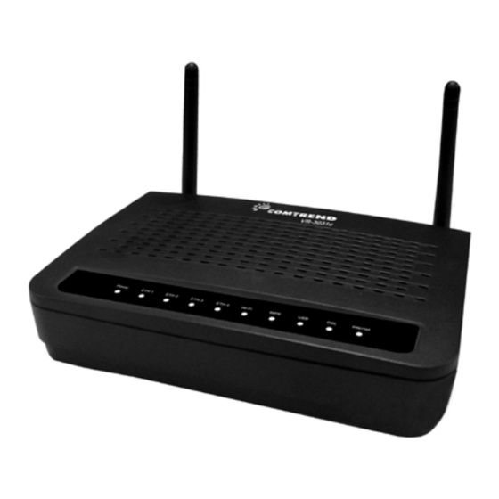
- Page 1 VR-3031u Multi-DSL Router User Manual Version A2.1, June 04, 2013 261099-019...
- Page 2 Preface This manual provides information related to the installation and operation of this device. The individual reading this manual is presumed to have a basic understanding of telecommunications terminology and concepts. If you find the product to be inoperable or malfunctioning, please contact technical support for immediate service by email at INT-support@comtrend.com For product update, new product release, manual revision, or software upgrades,...
- Page 3 Copyright Copyright©2013 Comtrend Corporation. All rights reserved. The information contained herein is proprietary to Comtrend Corporation. No part of this document may be translated, transcribed, reproduced, in any form, or by any means without prior written consent of Comtrend Corporation.
-
Page 4: Table Of Contents
Table of Contents CHAPTER 1 INTRODUCTION......................6 CHAPTER 2 INSTALLATION......................7 2.1 H ...........................7 ARDWARE ETUP 2.2 LED I ..........................9 NDICATORS CHAPTER 3 WEB USER INTERFACE.................... 11 3.1 D ........................11 EFAULT ETTINGS 3.2 IP C ........................12 ONFIGURATION 3.3 L ........................14 OGIN ROCEDURE CHAPTER 4 DEVICE INFORMATION...................16... - Page 5 6.5 R ............................80 OUTING 6.5.1 Default Gateway ......................80 6.5.2 Static Route........................81 6.5.3 Policy Routing ........................ 82 6.5.4 RIP..........................83 6.6 DNS .............................. 84 6.6.1 DNS Server ........................84 6.6.2 Dynamic DNS ......................... 85 6.6.3 DNS Entries ........................86 6.6.4 DNS Proxy/Relay ......................
- Page 6 APPENDIX E- CONNECTION SETUP ..................144 APPENDIX F - WPS EXTERNAL REGISTRAR................173 APPENDIX G - PRINTER SERVER ....................176...
-
Page 7: Chapter 1 Introduction
Chapter 1 Introduction The VR-3031u is an 802.11n compliant Multi-DSL router that supports both ADSL2+ and VDSL2. The latter is a brand new standard and technology perfect for triple play (Video, Voice and Data) applications. The VR-3031u comes with four 10/100 Base-T Ethernet ports, and one USB host, combining wired LAN connectivity and an integrated 802.11n WiFi WLAN Access Point (AP) for wireless connectivity. -
Page 8: Chapter 2 Installation
Chapter 2 Installation 2.1 Hardware Setup Follow the instructions below to complete the hardware setup. Non-stackable This device is not stackable – do not place units on top of each other, otherwise damage could occur. BACK PANEL The figure below shows the back panel of the device. Power ON Press the power button to the OFF position (OUT). - Page 9 WPS/WiFi Button Press and release WPS-WiFi button to activate WPS (make sure the WPS is enabled in Wireless->Security page). Press and hold WPS-WIFI button more than 5 seconds to enable/disable WiFi. Ethernet (LAN) Ports Use 10/100 BASE-T RJ-45 cables to connect up to four network devices. These ports are auto-sensing MDI/X;...
-
Page 10: Led Indicators
2.2 LED Indicators The front panel LED indicators are shown below and explained in the following table. This information can be used to check the status of the device and its connections. Color Mode Function The device is powered up. Green The device is powered down. - Page 11 Modem power off, modem in bridged mode or ADSL connection not present. In addition, if an IP or PPPoE session is dropped for any reason, other than an idle timeout, the light is turned off. Blink IP connected and IP Traffic is passing thru the device (either direction) Device attempted to become IP connected and failed (no DHCP response, no PPPoE response, PPPoE...
-
Page 12: Chapter 3 Web User Interface
Chapter 3 Web User Interface This section describes how to access the device via the web user interface (WUI) using an Internet browser such as Internet Explorer (version 5.0 and later). 3.1 Default Settings The factory default settings of this device are summarized below. LAN IP address: 192.168.1.1 LAN subnet mask: 255.255.255.0 Administrative access (username: root, password: 12345) -
Page 13: Ip Configuration
3.2 IP Configuration DHCP MODE When the VR-3031u powers up, the onboard DHCP server will switch on. Basically, the DHCP server issues and reserves IP addresses for LAN devices, such as your PC. To obtain an IP address from the DCHP server, follow the steps provided below. NOTE: The following procedure assumes you are running Windows XP. - Page 14 STATIC IP MODE In static IP mode, you assign IP settings to your PC manually. Follow these steps to configure your PC IP address to use subnet 192.168.1.x. NOTE: The following procedure assumes you are running Windows XP. However, the general steps involved are similar for most operating systems (OS).
-
Page 15: Login Procedure
3.3 Login Procedure Perform the following steps to login to the web user interface. NOTE: The default settings can be found in section 3.1 Default Settings. STEP 1: Start the Internet browser and enter the default IP address for the device in the Web address field. - Page 16 STEP 3: After successfully logging in for the first time, you will reach this screen. You can also reach this page by clicking on the following icon located at the top of the screen.
-
Page 17: Chapter 4 Device Information
Chapter 4 Device Information You can reach this page by clicking on the following icon located at the top of the screen. The web user interface window is divided into two frames, the main menu (at left) and the display screen (on the right). The main menu has several options and selecting each of these options opens a submenu with more selections. -
Page 18: Wan
4.1 WAN Select WAN from the Device Info submenu to display the configured PVC(s). Heading Description Interface Name of the interface for WAN Description Name of the WAN connection Type Shows the connection type VlanMuxId Shows 802.1Q VLAN ID IPv6 Shows WAN IPv6 status IGMP Shows Internet Group Management Protocol (IGMP) -
Page 19: Statistics
4.2 Statistics This selection provides LAN, WAN, ATM and xDSL statistics. NOTE: These screens are updated automatically every 15 seconds. Click Reset Statistics to perform a manual update. 4.2.1 LAN Statistics This screen shows data traffic statistics for each LAN interface. Heading Description Interface... -
Page 20: Wan Service
4.2.2 WAN Service This screen shows data traffic statistics for each WAN interface. Heading Description Interface WAN interfaces Description WAN service label Received/Transmitted - Bytes Number of Bytes - Pkts Number of Packets - Errs Number of packets with errors - Drops Number of dropped packets... -
Page 21: Xtm Statistics
4.2.3 XTM Statistics The following figure shows ATM (Asynchronous Transfer Mode)/PTM(Packet Transfer Mode) statistics. ATM Interface Statistics Heading Description Port Number ATM PORT (0-3) In Octets Number of octets received over the interface Out Octets Number of octets transmitted over the interface In Packets Number of packets received over the interface Out Packets... -
Page 22: Xdsl Statistics
4.2.4 xDSL Statistics The xDSL Statistics screen displays information corresponding to the xDSL type. The two examples below (VDSL & ADSL) show this variation. VDSL... - Page 23 ADSL Click the Reset Statistics button to refresh this screen. Field Description Mode G.Dmt, G.lite, T1.413, ADSL2, ADSL2+ Traffic Type Channel type Interleave or Fast Status Lists the status of the DSL link Link Power State Link output power state Line Coding (Trellis) Trellis On/Off SNR Margin (0.1 dB)
- Page 24 Field Description Rate (Kbps) Current sync rates downstream/upstream In VDSL mode, the following section is inserted. Number of bytes in Mux Data Frame Number of Mux Data Frames in a RS codeword Number of Mux Data Frames in an OH sub-frame Number of redundancy bytes in the RS codeword Number of data symbols the RS codeword spans Number of bits transmitted in each data symbol...
- Page 25 HEC Errors Total Number of Header Error Checksum errors OCD Errors Total Number of Out-of-Cell Delineation errors LCD Errors Total number of Loss of Cell Delineation Total Cells Total number of ATM cells (including idle + data cells) Data Cells Total number of ATM data cells Bit Errors Total number of bit errors...
- Page 26 xDSL TONE GRAPH Click Draw Tone Graph on the xDSL Statistics screen and a pop-up window will display the xDSL bits per tone status, as shown below.
-
Page 27: Route
4.3 Route Choose Route to display the routes that the VR-3031u has found. Field Description Destination Destination network or destination host Gateway Next hop IP address Subnet Mask Subnet Mask of Destination Flag U: route is up !: reject route G: use gateway H: target is a host R: reinstate route for dynamic routing... -
Page 28: Arp
4.4 ARP Click ARP to display the ARP information. Field Description IP address Shows IP address of host pc Flags Complete, Incomplete, Permanent, or Publish HW Address Shows the MAC address of host pc Device Shows the connection interface 4.5 DHCP Click DHCP to display all DHCP Leases. - Page 29 Field Description IPv6 Address Shows IP address of device/host/PC MAC Address Shows the Ethernet MAC address of the device/host/PC Duration Shows leased time in hours Expires In Shows how much time is left for each DHCP Lease...
-
Page 30: Nat Session
4.6 NAT Session Click the “Show All” button to display the following. Field Description Source IP The source IP from which the NAT session is established Source Port The source port from which the NAT session is established Destination IP The IP which the NAT session was connected to Destination Port The port which the NAT session was connected to... -
Page 31: Igmp Proxy
4.7 IGMP Proxy Field Description Interface The Source interface from which the IGMP report was received The WAN interface from which the multicast traffic is received Groups The destination IGMP group address Member The Source IP from which the IGMP report was received Timeout The time remaining before the IGMP report expires... -
Page 32: Ipv6
4.8 IPv6 4.8.1 IPv6 Info Field Description Interface WAN interface with IPv6 enabled Status Connection status of the WAN interface Address IPv6 Address of the WAN interface Prefix Prefix received/configured on the WAN interface Device Link-local Address The CPE's LAN Address Default IPv6 Gateway The default WAN IPv6 gateway IPv6 DNS Server... -
Page 33: Ipv6 Neighbor
4.8.2 IPv6 Neighbor Field Description IPv6 Address Ipv6 address of the device(s) found Flags Status of the neighbor device HW Address MAC address of the neighbor device Device Interface from which the device is located... -
Page 34: Ipv6 Route
4.8.3 IPv6 Route Field Description Destination Destination IP Address Gateway Gateway address used for destination IP Metric Metric specified for gateway Interface Interface used for destination IP... -
Page 35: Network Map
4.8.4 Network Map The network map is a graphical representation of router’s wan status and LAN devices. The feature is only available using a non-IE browser. -
Page 36: Chapter 5 Basic Setup
Chapter 5 Basic Setup You can reach this page by clicking on the following icon located at the top of the screen. 5.1 Layer 2 Interface Add or remove ATM, PTM and ETH WAN interface connections here. Click Add to create a new ATM interface (see Appendix E - Connection Setup). -
Page 37: Wan Service Setup
5.1.1 WAN Service Setup This screen allows for the configuration of WAN interfaces. Click the Add button to create a new connection. For connections on ATM or ETH WAN interfaces see Appendix E - Connection Setup. To remove a connection, select its Remove column radio button and click Remove. Heading Description Interface... -
Page 38: Nat
5.2 NAT To display this option, NAT must be enabled in at least one PVC. NAT is not an available option in Bridge mode. 5.2.1 Virtual Servers Virtual Servers allow you to direct incoming traffic from the WAN side (identified by Protocol and External port) to the internal server with private IP addresses on the LAN side. -
Page 39: Port Triggering
Consult the table below for field and header descriptions. Field/Header Description Use Interface Select a WAN interface from the drop-down box. Select a Service User should select the service from the list. Custom Service User can enter the name of their choice. Server IP Address Enter the IP address for the server. - Page 40 Click Save/Apply to save and apply the settings. Consult the table below for field and header descriptions. Field/Header Description Use Interface Select a WAN interface from the drop-down box. Select an Application User should select the application from the list. Custom Application User can enter the name of their choice.
-
Page 41: Dmz Host
5.2.3 DMZ Host The DSL router will forward IP packets from the WAN that do not belong to any of the applications configured in the Virtual Servers table to the DMZ host computer. To Activate the DMZ host, enter the DMZ host IP address and click Save/Apply. To Deactivate the DMZ host, clear the IP address field and click Save/Apply. -
Page 42: Ip Address Map
5.2.4 IP Address Map Mapping Local IP (LAN IP) to some specified Public IP (WAN IP). Field/Header Description Rule The number of the rule Type Mapping type from local to public. Local Start IP The beginning of the local IP Local End IP The ending of the local IP Public Start IP... - Page 43 One to One: mapping one local IP to a specific public IP Many to one: mapping a range of local IP to a specific public IP Many to many(Overload): mapping a range of local IP to a different range of public IP Many to many(No Overload): mapping a range of local IP to a same range of public IP...
-
Page 44: Ipsec Alg
5.2.5 IPSEC ALG IPSEC ALG provides multiple VPN passthrough connection support, allowing different clients on LAN side to establish a secured IP Connection to the WAN server. To enable IPSEC ALG, tick the checkbox and click the Save button. -
Page 45: Sip Alg
5.2.6 SIP ALG This page allows you to enable / disable SIP ALG. -
Page 46: Lan
5.3 LAN Configure the LAN interface settings and then click Apply/Save. Consult the field descriptions below for more details. GroupName: Select an Interface Group. LAN INTERFACE IP Address: Enter the IP address for the LAN port. Subnet Mask: Enter the subnet mask for the LAN port. - Page 47 IGMP Snooping: Standard Mode: In standard mode, multicast traffic will flood to all bridge ports when no client subscribes to a multicast group – even if IGMP snooping is enabled. Blocking Mode: In blocking mode, the multicast data traffic will be blocked and not flood to all bridge ports when there are no client subscriptions to any multicast group.
- Page 48 LAN INTERFACE To configure a secondary IP address, tick the checkbox outlined (in RED) below. IP Address: Enter the secondary IP address for the LAN port. Subnet Mask: Enter the secondary subnet mask for the LAN port. Ethernet Media Type: Configure auto negotiation, or enforce selected speed and duplex mode for the Ethernet ports.
-
Page 49: Lan Ipv6 Autoconfig
5.3.1 LAN IPv6 Autoconfig Configure the LAN interface settings and then click Save/Apply. Consult the field descriptions below for more details. - Page 50 LAN IPv6 Link-Local Address Configuration Heading Description EUI-64 Use EUI-64 algorithm to calculate link-local address from MAC address User Setting Use the Interface Identifier field to define a link-local address Static LAN IPv6 Address Configuration Heading Description Interface Address Configure static LAN IPv6 address and subnet prefix (prefix length is length required):...
- Page 51 To remove an entry, tick the corresponding checkbox in the Remove column and then click the Remove Entries button, as shown below. Heading Description Enable RADVD Enable use of router advertisement daemon RA interval Min(sec): Minimum time to send router advertisement RA interval Max(sec): Maximum time to send router advertisement Reachable Time(ms):...
-
Page 52: Static Ip Neighbor
5.3.2 Static IP Neighbor Click the Add button to display the following. Click Apply/Save to apply and save the settings. Heading Description IP Version The IP version used for the neighbor device IP Address Define the IP Address for the neighbor device MAC Address The MAC Address of the neighbor device Associated Interface... -
Page 53: Upnp
5.3.3 UPnP Select the checkbox provided and click Apply/Save to enable UPnP protocol. -
Page 54: Wireless
5.4 Wireless 5.4.1 Basic The Basic option allows you to configure basic features of the wireless LAN interface. Among other things, you can enable or disable the wireless LAN interface, hide the network from active scans, set the wireless network name (also known as SSID) and restrict the channel set based on country requirements. - Page 55 Option Description Hide Access Select Hide Access Point to protect the access point from detection Point by wireless active scans. To check AP status in Windows XP, open Network Connections from the start Menu and select View Available Network Connections. If the access point is hidden, it will not be listed there.
-
Page 56: Security
5.4.2 Security The following screen appears when Wireless Security is selected. The options shown here allow you to configure security features of the wireless LAN interface. Click Apply/Save to implement new configuration settings. WIRELESS SECURITY Setup requires that the user configure these settings using the Web User Interface (see the table below). - Page 57 The settings for WPA authentication are shown below. The settings for WPA-PSK authentication are shown next.
- Page 58 WEP Encryption This option specifies whether data sent over the network is encrypted. The same network key is used for data encryption and network authentication. Four network keys can be defined although only one can be used at any one time. Use the Current Network Key list box to select the appropriate network key.
-
Page 59: Chapter 6 Advanced Setup
Chapter 6 Advanced Setup You can reach this page by clicking on the following icon located at the top of the screen. 6.1 Auto-detection setup The auto-detection function is used for CPE to detect WAN service for either ETHWAN or xDSL interface. The feature is designed for the scenario that requires only one WAN service in different applications. - Page 60 Enter the PPP username/password given by your service provider for PPP service detection. Select a LAN-as-WAN Ethernet port for auto-detect: Select the Ethernet Port that will be used as ETHWAN during auto-detection.
- Page 61 WAN services list for ATM mode: A maximum of 7 WAN services with corresponding PVC are required to be configured for ADSL ATM mode. The services will be detected in order. Users can modify the 7 pre-configured services and select disable to ignore any of those services to meet their own requirement and also reduce the detection cycle.
- Page 62 Click "Apply/Save" to activate the auto-detect function. Options for each WAN service: These options are selectable for each WAN service. Users can pre-configure both WAN services and other provided settings to meet their deployed requirements. Auto Detection status and Restart The Auto-detection status is used to display the real time status of the Auto-detection feature.
- Page 63 Auto Detection notice Note: The following description concerning ETHWAN is for multiple LAN port devices only. 1) This feature will automatically detect one WAN service only. If customers require multiple WAN services, manual configuration is required. 2) If a physical ETHWAN port is detected, the Auto Detection for ETHWAN will be fixed on the physical ETHWAN port and cannot be configured for any LAN port;...
-
Page 64: Security
6.2 Security To display this function, you must enable the firewall feature in WAN Setup. For detailed descriptions, with examples, please consult Appendix A - Firewall. 6.2.1 IP Filtering This screen sets filter rules that limit IP traffic (Outgoing/Incoming). Multiple filter rules can be set and each applies at least one limiting condition. - Page 65 Consult the table below for field descriptions. Field Description Filter Name The filter rule label IP Version Select from the drop down menu. Protocol TCP, TCP/UDP, UDP, or ICMP. Source IP address Enter source IP address. Source Port (port or port:port) Enter source port number or range.
- Page 66 To add a filter (to allow incoming IP traffic), click the Add button. On the following screen, enter your filter criteria and then click Apply/Save. Consult the table below for field descriptions. Field Description Filter Name The filter rule label. IP Version Select from the drop down menu.
- Page 67 Field Description Destination IP address Enter destination IP address. Destination Port (port or port:port) Enter destination port number or range. At the bottom of this screen, select the WAN and LAN Interfaces to which the filter rule will apply. You may select all or just a subset. WAN interfaces in bridge mode or without firewall enabled are not available.
-
Page 68: Mac Filtering
6.2.2 MAC Filtering NOTE: This option is only available in bridge mode. Other modes use IP Filtering to perform a similar function. Each network device has a unique 48-bit MAC address. This can be used to filter (block or forward) packets based on the originating device. MAC filtering policy and rules for the VR-3031u can be set according to the following procedure. - Page 69 Click Save/Apply to save and activate the filter rule. Consult the table below for detailed field descriptions. Field Description Protocol Type PPPoE, IPv4, IPv6, AppleTalk, IPX, NetBEUI, IGMP Destination MAC Address Defines the destination MAC address Source MAC Address Defines the source MAC address Frame Direction Select the incoming/outgoing packet interface WAN Interfaces...
-
Page 70: Parental Control
6.3 Parental Control This selection provides WAN access control functionality. 6.3.1 Time Restriction This feature restricts access from a LAN device to an outside network through the device on selected days at certain times. Make sure to activate the Internet Time server synchronization as described in section 8.5 Internet Time, so that the... - Page 71 See below for field descriptions. Click Apply/Save to add a time restriction. User Name: A user-defined label for this restriction. Browser's MAC Address: MAC address of the PC running the browser. Other MAC Address: MAC address of another LAN device. Days of the Week: The days the restrictions apply.
-
Page 72: Url Filter
6.3.2 URL Filter This screen allows for the creation of a filter rule for access rights to websites based on their URL address and port number. Select URL List Type: Exclude or Include. Tick the Exclude radio button to deny access to the websites listed. Tick the Include radio button to restrict access to only those listed websites. - Page 73 A maximum of 100 entries can be added to the URL Filter list.
-
Page 74: Quality Of Service (Qos)
6.4 Quality of Service (QoS) NOTE: QoS must be enabled in at least one PVC to display this option. (see Appendix E - Connection Setup for detailed PVC setup instructions). To Enable QoS tick the checkbox and select a Default DSCP Mark. Click Apply/Save to activate QoS. -
Page 75: Qos Queue Setup
6.4.1 QoS Queue Setup Configure queues with different priorities to be used for QoS setup. In ATM mode, maximum 16 queues can be configured. In PTM mode, maximum 8 queues can be configured. For each Ethernet interface, maximum 3 queues can be configured. To add a queue, click the Add button. - Page 76 Note that if WMM function is disabled in Wireless Page, queues related to wireless will not take effect. This function follows the Differentiated Services rule of IP QoS. You can create a new Queue entry by clicking the Add button. Enable and assign an interface and precedence on the next screen.
-
Page 77: Qos Policer
6.4.2 QoS Policer To remove policers, check their remove-checkboxes, then click the Remove button. The Enable button will scan through every policers in the table. Policers with enable-checkbox checked will be enabled. Policers with enable-checkbox un-checked will be disabled. The enable-checkbox also shows status of the policer after page reload. To add a policer, click the Add button. - Page 78 Field Description Name Name of this policer rule Enable Enable/Disable this policer rule Meter Type Meter type used for this policer rule Committed Rate (kbps) Defines the rate allowed for committed packets Committed Burst Size Maximum amount of packets that can be processed by (bytes) this policer Conforming Action...
-
Page 79: Qos Classification
6.4.3 QoS Classification The network traffic classes are listed in the following table. Click Add to configure a network traffic class rule and Enable to activate it. To delete an entry from the list, click Remove. This screen creates a traffic class rule to classify the upstream traffic, assign queuing priority and optionally overwrite the IP header DSCP byte. - Page 80 Field Description Traffic Class Name Enter a name for the traffic class. Rule Order Last is the only option. Rule Status Disable or enable the rule. Classification Criteria Class Interface Select an interface (i.e. Local, eth0-4, wl0) Ether Type Set the Ethernet type (e.g. IP, ARP, IPv6). Source MAC Address A packet belongs to SET-1, if a binary-AND of its source MAC address with the Source MAC Mask is equal to the...
-
Page 81: Routing
6.5 Routing The following routing functions are accessed from this menu: Default Gateway, Static Route, Policy Routing, RIP and IPv6 Static Route. NOTE: In bridge mode, the RIP menu option is hidden while the other menu options are shown but ineffective. 6.5.1 Default Gateway Default gateway interface list can have multiple WAN interfaces served as system... -
Page 82: Static Route
6.5.2 Static Route This option allows for the configuration of static routes by destination IP. Click Add to create a static route or click Remove to delete a static route. After clicking Add the following will display. IP Version: Select the IP version to be IPv4. Destination IP address/prefix length: Enter the destination IP address. -
Page 83: Policy Routing
6.5.3 Policy Routing This option allows for the configuration of static routes by policy. Click Add to create a routing policy or Remove to delete one. On the following screen, complete the form and click Apply/Save to create a policy. Field Description Policy Name... -
Page 84: Rip
6.5.4 To activate RIP, configure the RIP version/operation mode and select the Enabled checkbox for at least one WAN interface before clicking Save/Apply. -
Page 85: Dns
6.6 DNS 6.6.1 DNS Server Select DNS Server Interface from available WAN interfaces OR enter static DNS server IP addresses for the system. In ATM mode, if only a single PVC with IPoA or static IPoE protocol is configured, Static DNS server IP addresses must be entered. DNS Server Interfaces can have multiple WAN interfaces served as system dns servers but only one will be used according to the priority with the first being the highest and the last one the lowest priority if the WAN interface is connected. -
Page 86: Dynamic Dns
6.6.2 Dynamic DNS The Dynamic DNS service allows you to map a dynamic IP address to a static hostname in any of many domains, allowing the VR-3031u to be more easily accessed from various locations on the Internet. To add a dynamic DNS service, click Add. The following screen will display. Click Apply/Save to save your settings. -
Page 87: Dns Entries
6.6.3 DNS Entries The DNS Entry page allows you to add domain names and IP address desired to be resolved by the DSL router. Choose Add or Remove to configure DNS Entry. The entries will become active after save/reboot. Enter the domain name and IP address that needs to be resolved locally, and click the Add Entry button. -
Page 88: Dns Proxy/Relay
6.6.4 DNS Proxy/Relay DNS proxy receives DNS queries and forwards DNS queries to the Internet. After the CPE gets answers from the DNS server, it replies to the LAN clients. Configure DNS proxy with the default setting, when the PC gets an IP via DHCP, the domain name, Home, will be added to PC’s DNS Suffix Search List, and the PC can access route with “Comtrend.Home”. -
Page 89: Dsl
6.7 DSL The DSL Settings screen allows for the selection of DSL modulation modes. For optimum performance, the modes selected should match those of your ISP. DSL Mode Data Transmission Rate - Mbps (Megabits per second) G.Dmt Downstream: 12 Mbps Upstream: 1.3 Mbps G.lite Downstream: 4 Mbps... - Page 90 DSL Mode Data Transmission Rate - Mbps (Megabits per second) Options Description Inner/Outer Pair Select the inner or outer pins of the twisted pair (RJ11 cable) Bitswap Enable Enables adaptive handshaking functionality SRA Enable Enables Seamless Rate Adaptation (SRA) Select DSL LED Normal (TR-68 compliant): Select this option for DSL LED to behavior operate normally (See menu 2.2 LED Indicator)
-
Page 91: Home Networking
6.8 Home Networking 6.8.1 Print Server This page allows you to enable or disable printer support. Please reference Appendix G to see the procedure for enabling the Printer Server. -
Page 92: Dlna
6.8.2 DLNA Enabling DLNA allows users to share digital media, like pictures, music and video, to other LAN devices from the digital media server. Insert USB drive to the USB host port on the back of router. Modify media library path to the corresponding path of the USB drive and click Apply/Save to enable the DLNA media server. -
Page 93: Storage Service
6.8.3 Storage Service This page displays storage devices attached to USB host. Display after storage device attached (for your reference). -
Page 94: Interface Grouping
6.9 Interface Grouping Interface Grouping supports multiple ports to PVC and bridging groups. Each group performs as an independent network. To use this feature, you must create mapping groups with appropriate LAN and WAN interfaces using the Add button. The Remove button removes mapping groups, returning the ungrouped interfaces to the Default group. - Page 95 Automatically Add Clients With Following DHCP Vendor IDs: Add support to automatically map LAN interfaces to PVC's using DHCP vendor ID (option 60). The local DHCP server will decline and send the requests to a remote DHCP server by mapping the appropriate LAN interface. This will be turned on when Interface Grouping is enabled.
- Page 96 1. Default: ENET1, ENET2, ENET3, and ENET4. 2. Video: nas_0_36, nas_0_37, and nas_0_38. The DHCP vendor ID is "Video". If the onboard DHCP server is running on "Default" and the remote DHCP server is running on PVC 0/36 (i.e. for set-top box use only). LAN side clients can get IP addresses from the CPE's DHCP server and access the Internet via PPPoE (0/33).
-
Page 97: Ip Tunnel
6.10 IP Tunnel 6.10.1 IPv6inIPv4 Configure 6in4 tunneling to encapsulate IPv6 traffic over explicitly-configured IPv4 links. Click the Add button to display the following. Options Description Tunnel Name Input a name for the tunnel Mechanism Mechanism used by the tunnel deployment Associated WAN Interface Select the WAN interface to be used by the tunnel... - Page 98 Options Description Associated LAN Interface Select the LAN interface to be included in the tunnel Manual/Automatic Select automatic for point-to-multipoint tunneling / manual for point-to-point tunneling IPv4 Mask Length The subnet mask length used for the IPv4 interface 6rd Prefix with Prefix Length Prefix and prefix length used for the IPv6 interface Border Relay IPv4 Address Input the IPv4 address of the other device...
-
Page 99: Ipv4Inipv6
6.10.2 IPv4inIPv6 Configure 4in6 tunneling to encapsulate IPv4 traffic over an IPv6-only environment. Click the Add button to display the following. Options Description Tunnel Name Input a name for the tunnel Mechanism Mechanism used by the tunnel deployment Associated WAN Interface Select the WAN interface to be used by the tunnel Associated LAN Interface Select the LAN interface to be included in the tunnel... -
Page 100: Certificate
6.11 Certificate A certificate is a public key, attached with its owner’s information (company name, server name, personal real name, contact e-mail, postal address, etc) and digital signatures. There will be one or more digital signatures attached to the certificate, indicating that these entities have verified that this certificate is valid. - Page 101 Field Description Certificate Name A user-defined name for the certificate. Common Name Usually, the fully qualified domain name for the machine. Organization Name The exact legal name of your organization. Do not abbreviate. State/Province Name The state or province where your organization is located. It cannot be abbreviated.
-
Page 102: Trusted Ca
6.11.2 Trusted CA CA is an abbreviation for Certificate Authority, which is a part of the X.509 system. It is itself a certificate, attached with the owner information of this certificate authority; but its purpose is not encryption/decryption. Its purpose is to sign and issue certificates, in order to prove that these certificates are valid. -
Page 103: Power Management
6.12 Power Management This screen allows for control of hardware modules to evaluate power consumption. Use the buttons to select the desired option, click Apply and check the response.
Need help?
Do you have a question about the VR-303 and is the answer not in the manual?
Questions and answers