Table of Contents
Advertisement
Advertisement
Table of Contents

Related Manuals for Comtrend Corporation VR-3031u


Summary of Contents for Comtrend Corporation VR-3031u
-
Page 1: User Manual
VR-3031u Multi-DSL Router User Manual Version A1.0, November 12, 2013 261099-021... - Page 2 Preface This manual provides information related to the installation and operation of this device. The individual reading this manual is presumed to have a basic understanding of telecommunications terminology and concepts. If you find the product to be inoperable or malfunctioning, please contact technical support for immediate service by email at INT-support@comtrend.com For product update, new product release, manual revision, or software upgrades,...
- Page 3 Copyright Copyright©2013 Comtrend Corporation. All rights reserved. The information contained herein is proprietary to Comtrend Corporation. No part of this document may be translated, transcribed, reproduced, in any form, or by any means without prior written consent of Comtrend Corporation.
-
Page 4: Table Of Contents
Table of Contents CHAPTER 1 INTRODUCTION ......................5 CHAPTER 2 INSTALLATION ......................6 2.1 H ........................... 6 ARDWARE ETUP 2.2 LED I ..........................8 NDICATORS CHAPTER 3 WEB USER INTERFACE .................... 10 3.1 D ........................10 EFAULT ETTINGS 3.2 IP C ........................ - Page 5 5.10 DSL ............................. 76 5.11 UP P ............................78 5.12 DNS P ........................79 ROXY ELAY 5.13 P ..........................80 RINT ERVER 5.14 I ......................... 81 NTERFACE ROUPING 5.15 IPS ............................84 5.15.1 IPSec Tunnel Mode Connections ..................84 5.16 C ..........................
-
Page 6: Chapter 1 Introduction
WiFi WLAN Access Point (AP) for wireless connectivity. The VR-3031u is a cost effective solution designed to meet the needs of ISPs and carriers planning on deploying a single DSL device for covering end users in different loop range areas. -
Page 7: Chapter 2 Installation
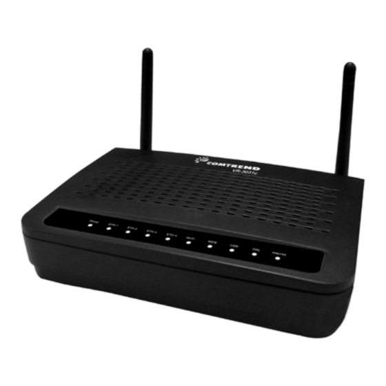
2.2 LED Indicators for details). NOTE: If pressed down for more than 60 seconds, the VR-3031u will go into a firmware update state (CFE boot mode). The firmware can then be updated using an Internet browser pointed to the default IP address. - Page 8 WPS/WiFi Button Press and release WPS-WiFi button to activate WPS (make sure the WPS is enabled in Wireless->Security page). Press and hold WPS-WIFI button more than 5 seconds to enable/disable WiFi. Ethernet (LAN) Ports Use 10/100 BASE-T RJ-45 cables to connect up to four network devices. These ports are auto-sensing MDI/X;...
-
Page 9: Led Indicators
2.2 LED Indicators The front panel LED indicators are shown below and explained in the following table. This information can be used to check the status of the device and its connections. Color Mode Function The device is powered up. Green The device is powered down. - Page 10 Modem power off, modem in bridged mode or ADSL connection not present. In addition, if an IP or PPPoE session is dropped for any reason, other than an idle timeout, the light is turned off. Blink IP connected and IP Traffic is passing thru the device (either direction) Device attempted to become IP connected and failed (no DHCP response, no PPPoE response, PPPoE...
-
Page 11: Chapter 3 Web User Interface
Chapter 3 Web User Interface This section describes how to access the device via the web user interface (WUI) using an Internet browser such as Internet Explorer (version 5.0 and later). 3.1 Default Settings The factory default settings of this device are summarized below. •... -
Page 12: Ip Configuration
3.2 IP Configuration DHCP MODE When the VR-3031u powers up, the onboard DHCP server will switch on. Basically, the DHCP server issues and reserves IP addresses for LAN devices, such as your PC. To obtain an IP address from the DCHP server, follow the steps provided below. - Page 13 STATIC IP MODE In static IP mode, you assign IP settings to your PC manually. Follow these steps to configure your PC IP address to use subnet 192.168.1.x. NOTE: The following procedure assumes you are running Windows XP. However, the general steps involved are similar for most operating systems (OS).
-
Page 14: Wizard Setup
3.3 Wizard Setup After starting the Wizard you will be brought to the Welcome page. Click the Continue button. - Page 15 Set new login password and click the Continue button. The new password must have a minimum of 6 characters and a maximum of 16. Letters or numbers can be used. Passwords with characters repeated more than 2 times such as 111 or eee for example are not permitted.
- Page 16 If there is no DSL connection, the following page will pop up to inform you. (For reference)
- Page 17 Input the Username and Password as provided by your ISP (Internet Service Provider). Click the Continue button.
- Page 18 This page informs you that the settings are being saved.
- Page 19 If the wrong Username and/or Password are used the following page will pop up to inform you. (For reference)
- Page 20 Upon Username and Password authentication, you will be asked to set a new WiFi Password. Input the new Password and click the Continue button. The new password must have a minimum of 8 characters and a maximum of 64.
- Page 21 If WiFi was set up correctly, it goes to end of wizard page. Click on the Advanced Configuration button to bring you to the Advanced Settings Page. If you click the Complete button you will be brought to the ctbc company web page.
-
Page 22: Login To Advanced Web User Interface
3.4 Login to Advanced Web User Interface Perform the following steps to login to the web user interface. NOTE: Before accessing this page, make sure to complete the Wizard Setup. STEP 1: Start the Internet browser and enter the default IP address for the device in the Web address field. - Page 23 STEP 3: After successfully logging in for the first time, you will reach this screen.
-
Page 24: Chapter 4 Device Information
Chapter 4 Device Information The web user interface window is divided into two frames, the main menu (at left) and the display screen (on the right). The main menu has several options and selecting each of these options opens a submenu with more selections. NOTE: The menu items shown are based upon the configured connection(s) and user account privileges. -
Page 25: Wan
4.1 WAN Select WAN from the Device Info submenu to display the configured PVC(s). Heading Description Interface Name of the interface for WAN Description Name of the WAN connection Type Shows the connection type VlanMuxId Shows 802.1Q VLAN ID IGMP Shows Internet Group Management Protocol (IGMP) status Shows Network Address Translation (NAT) status Firewall... -
Page 26: Statistics
4.2 Statistics This selection provides LAN, WAN, ATM/PTM and xDSL statistics. NOTE: These screens are updated automatically every 15 seconds. Click Reset Statistics to perform a manual update. 4.2.1 LAN Statistics This screen shows data traffic statistics for each LAN interface. Heading Description Interface... -
Page 27: Wan Service
4.2.2 WAN Service This screen shows data traffic statistics for each WAN interface. Heading Description Interface WAN interfaces Description WAN service label Received/Transmitted - Bytes Number of Bytes - Pkts Number of Packets - Errs Number of packets with errors - Drops Number of dropped packets 4.2.3... - Page 28 ATM Interface Statistics Heading Description Port Number ATM PORT (0-3) In Octets Number of received octets over the interface Out Octets Number of transmitted octets over the interface In Errors Number of cells dropped due to uncorrectable HEC errors In Unknown Number of received cells discarded during cell header validation, including cells with unrecognized VPI/VCI values, and cells with invalid cell header patterns.
-
Page 29: Xdsl Statistics
4.2.4 xDSL Statistics The xDSL Statistics screen displays information corresponding to the xDSL type. The two examples below (VDSL & ADSL) show this variation. VDSL... - Page 30 ADSL Click the Reset Statistics button to refresh this screen. Field Description Mode G.Dmt, G.lite, T1.413, ADSL2, ADSL2+ Traffic Type Channel type Interleave or Fast Status Lists the status of the DSL link Link Power State Link output power state Line Coding (Trellis) Trellis On/Off SNR Margin (0.1 dB)
- Page 31 Attenuation (0.1 dB) Estimate of average loop attenuation in the downstream direction Output Power (0.1 dBm) Total upstream output power Attainable Rate (Kbps) The sync rate you would obtain Rate (Kbps) Current sync rates downstream/upstream In VDSL mode, the following section is inserted. Number of bytes in Mux Data Frame Number of Mux Data Frames in a RS codeword Number of Mux Data Frames in an OH sub-frame...
- Page 32 RS Correctable Errors Total Number of RS with correctable errors RS Uncorrectable Errors Total Number of RS words with uncorrectable errors HEC Errors Total Number of Header Error Checksum errors OCD Errors Total Number of Out-of-Cell Delineation errors LCD Errors Total number of Loss of Cell Delineation Total Cells Total number of ATM cells (including idle + data cells)
- Page 34 xDSL TONE GRAPH Click Draw Tone Graph on the xDSL Statistics screen and a pop-up window will display the xDSL bits per tone status, as shown below.
-
Page 35: Route
4.3 Route Choose Route to display the routes that the VR-3031u has found. Field Description Destination Destination network or destination host Gateway Next hub IP address Subnet Mask Subnet Mask of Destination Flag U: route is up !: reject route... -
Page 36: Arp
4.4 ARP Click ARP to display the ARP information. Field Description IP address Shows IP address of host pc Flags Complete, Incomplete, Permanent, or Publish HW Address Shows the MAC address of host pc Device Shows the connection interface... -
Page 37: Dhcp
4.5 DHCP Click DHCP to display all DHCP Leases. Field Description Hostname Shows the device/host/PC network name MAC Address Shows the Ethernet MAC address of the device/host/PC IP Address Shows IP address of device/host/PC Expires In Shows how much time is left for each DHCP Lease... -
Page 38: Nat Session
4.6 NAT Session Click the “Show All” button to display the following. Field Description Source IP The source IP from which the NAT session is established Source Port The source port from which the NAT session is established Destination IP The IP which the NAT session was connected to Destination Port The port which the NAT session was connected to... -
Page 39: Igmp Info
4.7 IGMP Info Field Description Interface The Source interface from which the IGMP report was received The WAN interface from which the multicast traffic is received Groups The destination IGMP group address Member The Source IP from which the IGMP report was received Timeout The time remaining before the IGMP report expires... - Page 40 4.8 3G Device needs to be attached in order to display the information for the 3G device.
-
Page 41: Chapter 5 Advanced Setup
Chapter 5 Advanced Setup 5.1 Layer 2 Interface The ATM, PTM and ETH WAN interface screens are described here. 5.1.1 ATM Interface Add or remove ATM interface connections here. Click Add to create a new ATM interface (see Appendix G - Connection Setup NOTE: Up to 8 ATM interfaces can be created and saved in flash memory. -
Page 42: Eth Wan Interface
5.1.3 ETH WAN INTERFACE This screen displays the Ethernet WAN Interface configuration. NOTE: This option only applies to models with an Ethernet WAN port. Click Add to create a new connection (see Appendix G NOTE: One Ethernet WAN interface can be created and saved in flash memory. To remove a connection, select its Remove column radio button and click remove. -
Page 43: Wan
5.2 WAN This screen allows for the configuration of WAN interfaces. Click the Add button to create a new connection. For connections on ATM or ETH WAN interfaces see Appendix G NOTE: ETH and ATM service connections cannot coexist. In Default Mode, up to 8 WAN connections can be configured;... -
Page 44: Service Setup
5.2.1 3G Service Setup This page is used to configure 3G service, and let route access internet via 3G. If users don’t insert 3G dongle, users can not configure the 3G WAN interface. Click the Add button to create a new connection. To remove a connection, select its Remove column radio button and click Remove. - Page 45 Input your Access Point Name and Dial Number and click Next. For further setup instructions please see Appendix G - Connection Setup.
-
Page 46: Auto-Detection Setup
5.3 Auto-detection setup Tick the Enable auto-detect to display the following: Follow the onscreen instructions to configure the interfaces that are available within your network, specify the wan parameters to be used and click the Apply/Save button to activate the auto-detection function. -
Page 47: Nat
5.4 NAT To display this option, NAT must be enabled in at least one PVC shown on the Advanced Setup - WAN screen. NAT is not an available option in Bridge mode. 5.4.1 Virtual Servers Virtual Servers allow you to direct incoming traffic from the WAN side (identified by Protocol and External port) to the Internal server with private IP addresses on the LAN side. - Page 48 Consult the table below for field and header descriptions. Field/Header Description Use Interface Select a WAN interface from the drop-down box. Select a Service User should select the service from the list. Custom Service User can enter the name of their choice. Server IP Address Enter the IP address for the server.
-
Page 49: Port Triggering
5.4.2 Port Triggering Some applications require that specific ports in the firewall be opened for access by the remote parties. Port Triggers dynamically 'Open Ports' in the firewall when an application on the LAN initiates a TCP/UDP connection to a remote party using the 'Triggering Ports'. - Page 50 Consult the table below for field and header descriptions. Field/Header Description Use Interface Select a WAN interface from the drop-down box. Select an Application User should select the application from the list. Custom Application User can enter the name of their choice. Trigger Port Start Enter the starting trigger port number (when you select custom application).
-
Page 51: Dmz Host
5.4.3 DMZ Host The DSL router will forward IP packets from the WAN that do not belong to any of the applications configured in the Virtual Servers table to the DMZ host computer. To Activate the DMZ host, enter the DMZ host IP address and click Save/Apply. To Deactivate the DMZ host, clear the IP address field and click Save/Apply. -
Page 52: Ip Address Map
5.4.4 IP Address Map Mapping Local IP (LAN IP) to some specified Public IP (WAN IP). Field/Header Description Rule The number of the rule Type Mapping type from local to public. Local Start IP The beginning of the local IP Local End IP The ending of the local IP Public Start IP... - Page 53 Select a Service, then click the Save/Apply button. One to One: mapping one local IP to a specific public IP Many to one: mapping a range of local IP to a specific public IP Many to many(Overload): mapping a range of local IP to a different range of public IP Many to many(No Overload): mapping a range of local IP to a same range of public IP...
-
Page 54: Sip Alg
5.4.5 SIP ALG This page allows you to enable / disable SIP ALG. 5.4.6 IPSEC ALG IPSEC ALG provides multiple VPN passthrough connection support, allowing different clients on LAN side to establish a secured IP Connection to the WAN server. To enable IPSEC ALG, tick the checkbox and click the Save button. -
Page 55: Security
5.5 Security To display this function, you must enable the firewall feature in WAN Setup. For detailed descriptions, with examples, please consult Appendix A - Firewall. 5.5.1 IP Filtering This screen sets filter rules that limit IP traffic (Outgoing/Incoming). Multiple filter rules can be set and each applies at least one limiting condition. - Page 56 Consult the table below for field descriptions. Field Description Filter Name The filter rule label IP Version Select from the drop down menu. Protocol TCP, TCP/UDP, UDP, or ICMP. Source IP address Enter source IP address. Source Port (port or port:port) Enter source port number or range.
- Page 57 Consult the table below for field descriptions. Field Description Filter Name The filter rule label IP Version Select from the drop down menu. Protocol TCP, TCP/UDP, UDP, or ICMP. Source IP address Enter source IP address. Source Port (port or port:port) Enter source port number or range.
-
Page 58: Mac Filtering
Each network device has a unique 48-bit MAC address. This can be used to filter (block or forward) packets based on the originating device. MAC filtering policy and rules for the VR-3031u can be set according to the following procedure. The MAC Filtering Global Policy is defined as follows. FORWARDED means that all MAC layer frames will be FORWARDED except those matching the MAC filter rules. - Page 59 Consult the table below for detailed field descriptions. Field Description Protocol Type PPPoE, IPv4, IPv6, AppleTalk, IPX, NetBEUI, IGMP Destination MAC Address Defines the destination MAC address Source MAC Address Defines the source MAC address Frame Direction Select the incoming/outgoing packet interface WAN Interfaces Applies the filter to the selected bridge interface.
-
Page 60: Parental Control
5.6 Parental Control This selection provides WAN access control functionality. 5.6.1 Time Restriction This feature restricts access from a LAN device to an outside network through the device on selected days at certain times. Make sure to activate the Internet Time server synchronization as described in section 8.4, so that the scheduled times... -
Page 61: Url Filter
See below for field descriptions. Click Apply/Save to add a time restriction. User Name: A user-defined label for this restriction. Browser's MAC Address: MAC address of the PC running the browser. Other MAC Address: MAC address of another LAN device. Days of the Week: The days the restrictions apply. - Page 62 A maximum of 100 entries can be added to the URL Filter list.
-
Page 63: Quality Of Service (Qos)
5.7 Quality of Service (QoS) NOTE: QoS must be enabled in at least one PVC to display this option. (see Appendix G for detailed PVC setup instructions). To Enable QoS tick the checkbox and select a Default DSCP Mark. Click Apply/Save to activate QoS. QoS and DSCP Mark are defined as follows: Quality of Service (QoS): This provides different priority to different users or data flows, or guarantees a certain level of performance to a data flow in accordance with... -
Page 64: Qos Queue Setup
5.7.1 QoS Queue Setup Configure queues with different priorities to be used for QoS setup. In ATM mode, maximum 16 queues can be configured. In PTM mode, maximum 8 queues can be configured. For each Ethernet interface, maximum 3 queues can be configured. To add a queue, click the Add button. - Page 65 Note that if WMM function is disabled in Wireless Page, queues related to wireless will not take effect. This function follows the Differentiated Services rule of IP QoS. You can create a new Queue entry by clicking the Add button. Enable and assign an interface and precedence on the next screen.
-
Page 66: Qos Policer
5.7.2 QoS Policer To remove policers, check their remove-checkboxes, then click the Remove button. The Enable button will scan through every policers in the table. Policers with enable-checkbox checked will be enabled. Policers with enable-checkbox un-checked will be disabled. The enable-checkbox also shows status of the policer after page reload. To add a policer, click the Add button. - Page 67 Field Description Name Name of this policer rule Enable Enable/Disable this policer rule Meter Type Meter type used for this policer rule Committed Rate (kbps) Defines the rate allowed for committed packets Committed Burst Size Maximum amount of packets that can be processed by (bytes) this policer Conforming Action...
-
Page 68: Qos Classification
5.7.3 QoS Classification The network traffic classes are listed in the following table. Click Add to configure a network traffic class rule and Enable to activate it. To delete an entry from the list, click Remove. This screen creates a traffic class rule to classify the upstream traffic, assign queuing priority and optionally overwrite the IP header DSCP byte. - Page 69 Field Description Traffic Class Name Enter a name for the traffic class. Rule Order Last is the only option. Rule Status Disable or enable the rule. Classification Criteria Class Interface Select an interface (i.e. Local, eth0-4, wl0) Ether Type Set the Ethernet type (e.g. IP, ARP, IPv6). Source MAC Address A packet belongs to SET-1, if a binary-AND of its source MAC address with the Source MAC Mask is equal to the...
-
Page 70: Routing
5.8 Routing This following routing functions are accessed from this menu: Default Gateway, Static Route, Policy Routing, RIP and IPv6 Static Route. NOTE: In bridge mode, the RIP menu option is hidden while the other menu options are shown but ineffective. 5.8.1 Default Gateway Default gateway interface list can have multiple WAN interfaces served as system... -
Page 71: Static Route
5.8.2 Static Route This option allows for the configuration of static routes by destination IP. Click Add to create a static route or click Remove to delete a static route. After clicking Add the following screen will display. IP Version: Select the IP version to be IPv4. ... -
Page 72: Policy Routing
5.8.3 Policy Routing This option allows for the configuration of static routes by policy. Click Add to create a routing policy or Remove to delete one. On the following screen, complete the form and click Save/Apply to create a policy. - Page 73 Field Description Policy Name Name of the route policy Physical LAN Port Specify the port to use this route policy Source IP IP Address to be routed Use Interface Interface that traffic will be directed to Default Gateway IP IP Address of the default gateway...
-
Page 74: Rip
5.8.4 To activate RIP, configure the RIP version/operation mode and select the Enabled checkbox for at least one WAN interface before clicking Save/Apply. -
Page 75: Dns
5.9 DNS 5.9.1 DNS Server Select DNS Server Interface from available WAN interfaces OR enter static DNS server IP addresses for the system. In ATM mode, if only a single PVC with IPoA or static IPoE protocol is configured, Static DNS server IP addresses must be inputted. Click Apply/Save to save the new configuration. -
Page 76: Dynamic Dns
Dynamic DNS The Dynamic DNS service allows you to map a dynamic IP address to a static hostname in any of many domains, allowing the VR-3031u to be more easily accessed from various locations on the Internet. To add a dynamic DNS service, click Add. The following screen will display. -
Page 77: Dsl
Consult the table below for field descriptions. Field Description D-DNS provider Select a dynamic DNS provider from the list Hostname Enter the name of the dynamic DNS server Interface Select the interface from the list Username Enter the username of the dynamic DNS server Password Enter the password of the dynamic DNS server 5.10 DSL... - Page 78 DSL Mode Data Transmission Rate - Mbps (Megabits per second) G.Dmt Downstream: 12 Mbps Upstream: 1.3 Mbps G.lite Downstream: 4 Mbps Upstream: 0.5 Mbps T1.413 Downstream: 8 Mbps Upstream: 1.0 Mbps ADSL2 Downstream: 12 Mbps Upstream: 1.0 Mbps AnnexL Supports longer loops but with reduced transmission rates ADSL2+ Downstream: 24 Mbps Upstream: 1.0 Mbps...
-
Page 79: Upnp
5.11 UPnP Select the checkbox provided and click Apply/Save to enable UPnP protocol. -
Page 80: Dns Proxy/Relay
5.12 DNS Proxy/Relay To enable DNS Proxy, select the corresponding checkbox and then enter Host and Domain names, as the example shown below. Click Apply/Save to continue. Enabling the DNS Relay function allows the cpe to relay public DNS servers received from WAN interface to DHCP clients. -
Page 81: Print Server
5.13 Print Server The VR-3031u can provide printer support through an optional USB2.0 host port. If your device has this port, refer to Appendix F - Printer Server for detailed setup instructions. -
Page 82: Interface Grouping
5.14 Interface Grouping Interface Grouping supports multiple ports to PVC and bridging groups. Each group performs as an independent network. To use this feature, you must create mapping groups with appropriate LAN and WAN interfaces using the Add button. The Remove button removes mapping groups, returning the ungrouped interfaces to the Default group. - Page 83 Automatically Add Clients With Following DHCP Vendor IDs: Add support to automatically map LAN interfaces to PVC's using DHCP vendor ID (option 60). The local DHCP server will decline and send the requests to a remote DHCP server by mapping the appropriate LAN interface. This will be turned on when Interface Grouping is enabled.
- Page 84 The Interface Grouping configuration will be: 1. Default: ENET1, ENET2, ENET3, and ENET4. 2. Video: nas_0_36, nas_0_37, and nas_0_38. The DHCP vendor ID is "Video". If the onboard DHCP server is running on "Default" and the remote DHCP server is running on PVC 0/36 (i.e.
-
Page 85: Ipsec
5.15 IPSec 5.15.1 IPSec Tunnel Mode Connections You can add, edit or remove IPSec tunnel mode connections from this page. Click Add New Connection to add a new IPSec termination rule. The following screen will display. - Page 86 IPSec Connection Name User-defined label Tunnel Mode Select tunnel protocol, AH (Authentication Header) or ESP (Encapsulating Security Payload) for this tunnel. Remote IPSec Gateway Address The location of the Remote IPSec Gateway. IP address or domain name can be used. Tunnel access from local IP Specify the acceptable host IP on the local addresses...
- Page 87 Auto(IKE) Key Exchange Method Pre-Shared Key / Certificate (X.509) Input Pre-shared key / Choose Certificate Perfect Forward Secrecy Enable or Disable Advanced IKE Settings Select Show Advanced Settings to reveal the advanced settings options shown below. Advanced IKE Settings Select Hide Advanced Settings to hide the advanced settings options shown above.
- Page 88 Encryption Algorithm DES / 3DES / AES (aes-cbc) Encryption Key DES: 16 digit Hex, 3DES: 48 digit Hex Authentication Algorithm MD5 / SHA1 Authentication Key MD5: 32 digit Hex, SHA1: 40 digit Hex SPI (default is 101) Enter a Hex value from 100-FFFFFFFF...
-
Page 89: Certificate
5.16 Certificate A certificate is a public key, attached with its owner’s information (company name, server name, personal real name, contact e-mail, postal address, etc) and digital signatures. There will be one or more digital signatures attached to the certificate, indicating that these entities have verified that this certificate is valid. - Page 90 The following table is provided for your reference. Field Description Certificate Name A user-defined name for the certificate. Common Name Usually, the fully qualified domain name for the machine. Organization Name The exact legal name of your organization. Do not abbreviate. State/Province Name The state or province where your organization is located.
-
Page 91: Trusted Ca
5.16.2 Trusted CA CA is an abbreviation for Certificate Authority, which is a part of the X.509 system. It is itself a certificate, attached with the owner information of this certificate authority; but its purpose is not encryption/decryption. Its purpose is to sign and issue certificates, in order to prove that these certificates are valid. -
Page 92: Power Management
5.17 Power Management This screen allows for control of hardware modules to evaluate power consumption. Use the buttons to select the desired option, click Apply and check the response. -
Page 93: Multicast
5.18 Multicast Input new IGMP or MLD protocol configuration fields if you want modify default values shown. Then click Apply/Save. Field Description Default Version Define IGMP using version with video server. Query Interval The query interval is the amount of time in seconds between IGMP General Query messages sent by the router (if the router is the querier on this subnet). - Page 94 Field Description Last Member Query The last member query interval is the amount of time Interval in seconds that the IGMP router waits to receive a response to a Group-Specific Query message. The last member query interval is also the amount of time in seconds between successive Group-Specific Query messages.
-
Page 95: Chapter 6 Wireless
Chapter 6 Wireless The Wireless menu provides access to the wireless options discussed below. 6.1 Basic The Basic option allows you to configure basic features of the wireless LAN interface. Among other things, you can enable or disable the wireless LAN interface, hide the network from active scans, set the wireless network name (also known as SSID) and restrict the channel set based on country requirements. - Page 96 Option Description Hide Access Select Hide Access Point to protect the access point from detection Point by wireless active scans. To check AP status in Windows XP, open Network Connections from the start Menu and select View Available Network Connections. If the access point is hidden, it will not be listed there.
-
Page 97: Security
6.2 Security The following screen appears when Wireless Security is selected. The options shown here allow you to configure security features of the wireless LAN interface. Click Apply/Save to implement new configuration settings. WIRELESS SECURITY Setup requires that the user configure these settings using the Web User Interface (see the table below). - Page 98 Network Authentication This option specifies whether a network key is used for authentication to the wireless network. If network authentication is set to Open, then no authentication is provided. Despite this, the identity of the client is still verified. Each authentication type has its own settings. For example, selecting 802.1X authentication will reveal the RADIUS Server IP address, Port and Key fields.
- Page 99 WPA/WAPI passphrase: WPA-PSK uses a simple and consistent method to secure your network using a passphrase (also referred to as a shared secret) that needs to be inputted in both the wireless access point/router and the WPA clients. The shared secret can consist of between 8 and 63 characters and can include spaces.
-
Page 100: Mac Filter
6.3 MAC Filter This option allows access to the router to be restricted based upon MAC addresses. To add a MAC Address filter, click the Add button shown below. To delete a filter, select it from the MAC Address table below and click the Remove button. Option Description Select... -
Page 101: Wireless Bridge
6.4 Wireless Bridge This screen allows for the configuration of wireless bridge features of the WLAN interface. See the table beneath for detailed explanations of the various options. Click Save/Apply to implement new configuration settings. Feature Description AP Mode Selecting Wireless Bridge (aka Wireless Distribution System) disables Access Point (AP) functionality, while selecting Access Point enables AP functionality. -
Page 102: Advanced
6.5 Advanced The Advanced screen allows you to configure advanced features of the wireless LAN interface. You can select a particular channel on which to operate, force the transmission rate to a particular speed, set the fragmentation threshold, set the RTS threshold, set the wakeup interval for clients in power-save mode, set the beacon interval for the access point, set XPress mode and set whether short or long preambles are used. - Page 103 Field Description Band Set to 2.4 GHz for compatibility with IEEE 802.11x standards. The new amendment allows IEEE 802.11n units to fall back to slower speeds so that legacy IEEE 802.11x devices can coexist in the same network. IEEE 802.11g creates data-rate parity at 2.4 GHz with the IEEE 802.11a standard, which has a 54 Mbps rate at 5 GHz.
- Page 104 Field Description Fragmentation A threshold, specified in bytes, that determines whether Threshold packets will be fragmented and at what size. On an 802.11 WLAN, packets that exceed the fragmentation threshold are fragmented, i.e., split into, smaller units suitable for the circuit size. Packets smaller than the specified fragmentation threshold value are not fragmented.
-
Page 105: Site Survey
6.6 Site Survey The graph displays wireless APs found in your neighborhood by channel. -
Page 106: Station Info
6.7 Station Info This page shows authenticated wireless stations and their status. Click the Refresh button to update the list of stations in the WLAN. Consult the table below for descriptions of each column heading. Heading Description Lists the MAC address of all the stations. Associated Lists all the stations that are associated with the Access Point, along with the amount of time since packets were transferred... -
Page 107: Chapter 7 Diagnostics
Chapter 7 Diagnostics The first Diagnostics screen is a dashboard that shows overall connection status. If a test displays a fail status, click the button to retest and confirm the error. If a test continues to fail, click Help and follow the troubleshooting procedures. The second Diagnostics screen (Fault Management) is used for VDSL diagnostics. -
Page 109: Chapter 8 Management
Chapter 8 Management The Management menu has the following maintenance functions and processes: 8.1 Settings This includes Backup Settings, Update Settings, and Restore Default screens. 8.1.1 Backup Settings To save the current configuration to a file on your PC, click Backup Settings. You will be prompted for backup file location. -
Page 110: Restore Default
PC IP configuration to match any new settings. NOTE: This entry has the same effect as the Reset button. The VR-3031u board hardware and the boot loader support the reset to default. If the Reset button is continuously pressed for more than 5 seconds, the boot loader... -
Page 111: System Log
8.2 System Log This function allows a system log to be kept and viewed upon request. Follow the steps below to configure, enable, and view the system log. STEP 1: Click Configure System Log, as shown below (circled in Red). STEP 2: Select desired options and click Apply/Save. - Page 112 “Emergency” down to this configured level will be recorded to the log buffer on the VR-3031u SDRAM. When the log buffer is full, the newer event will wrap up to the top of the log buffer and overwrite the old event.
-
Page 113: Client
8.3 TR-069 Client WAN Management Protocol (TR-069) allows an Auto-Configuration Server (ACS) to perform auto-configuration, provision, collection, and diagnostics to this device. Select desired values and click Apply/Save to configure TR-069 client options. The table below is provided for ease of reference. Option Description Inform... - Page 114 Password used to authenticate an ACS making a Connection Request to the CPE. IP address and port the ACS uses to connect to VR-3031u. The Get RPC Methods button forces the CPE to establish an immediate connection to the ACS. This may be used to discover the set of methods supported by the ACS or CPE.
-
Page 115: Internet Time
8.4 Internet Time This option automatically synchronizes the router time with Internet timeservers. To enable time synchronization, tick the corresponding checkbox , choose your preferred time server(s), select the correct time zone offset, and click Save/Apply. NOTE: Internet Time must be activated to use Parental Control. -
Page 116: Access Control
8.5 Access Control 8.5.1 Passwords This screen is used to configure the user account access passwords for the device. Access to the VR-3031u is controlled through the following three user accounts: • root - unrestricted access to change and view the configuration. -
Page 117: Services
8.5.2 Services Select each drop-down menu item and click Apply/Save to configure your Setting. -
Page 118: Ip Address
8.5.3 IP Address The IP Address Access Control mode, if enabled, permits access to local management services from IP addresses contained in the Access Control List. If the Access Control mode is disabled, the system will not validate IP addresses for incoming packets. -
Page 119: Update Software
8.6 Update Software This option allows for firmware upgrades from a locally stored file. STEP 1: Obtain an updated software image file from your ISP. STEP 2: Enter the path and filename of the firmware image file in the Software File Name field or click the Browse button to locate the image file. -
Page 120: Reboot
8.7 Reboot To save the current configuration and reboot the router, click Save/Reboot. NOTE: You may need to close the browser window and wait for 2 minutes before reopening it. It may also be necessary, to reset your PC IP configuration. -
Page 121: Appendix A - Firewall
Appendix A - Firewall STATEFUL PACKET INSPECTION Refers to an architecture, where the firewall keeps track of packets on each connection traversing all its interfaces and makes sure they are valid. This is in contrast to static packet filtering which only examines a packet based on the information in the packet header. - Page 122 Example 1: Filter Name : In_Filter1 Protocol : TCP Policy : Allow Source IP Address : 210.168.219.45 Source Subnet Mask : 255.255.0.0 Source Port : 80 Dest. IP Address : NA Dest. Subnet Mask : NA Dest. Port : NA Selected WAN interface : br0 This filter will ACCEPT all TCP packets coming from WAN interface “br0”...
- Page 123 DAYTIME PARENTAL CONTROL This feature restricts access of a selected LAN device to an outside Network through the VR-3031u, as per chosen days of the week and the chosen times. Example: User Name : FilterJohn Browser's MAC Address : 00:25:46:78:63:21...
-
Page 124: Appendix B - Pin Assignments
Appendix B - Pin Assignments ETHERNET Ports (RJ45) Definition Definition Transmit data+ Transmit data- Receive data- Receive data+... -
Page 125: Appendix C - Specifications
Appendix C - Specifications Hardware Interface RJ-11 X 1 for ADSL2+/VDSL2, RJ-45 X 4 for LAN (10/100 Base-T), Reset Button X 1, WPS/WiFi on/off button x1, Wi-Fi Antennas X 2, Power Switch X 1, USB Host WAN Interface ADSL2+ ..Downstream : 24 Mbps Upstream : 1.3 Mbps ITU-T G.992.5, ITU-T G.992.3, ITU-T G.992.1, ANSI T1.413 Issue 2, AnnexM VDSL2 ..Downstream : 100 Mbps... - Page 126 Operating temperature ......0 ~ 40 degrees Celsius Relative humidity ........5 ~ 95% (non-condensing) Dimensions ........171 mm (W) x 39 mm (H) x 122 mm (D) Kit Weight (1*VR-3031u, 1*RJ11 cable, 1*RJ45 cable, 1*power adapter) = 0.6 kg NOTE: Specifications are subject to change without notice...
-
Page 127: Appendix D - Ssh Client
Appendix D - SSH Client Unlike Microsoft Windows, Linux OS has a ssh client included. For Windows users, there is a public domain one called “putty” that can be downloaded from here: http://www.chiark.greenend.org.uk/~sgtatham/putty/download.html To access the ssh client you must first enable SSH access for the LAN or WAN from the Management ... -
Page 128: Appendix E - Wsc External Registrar
Appendix E - WSC External Registrar Follow these steps to add an external registrar using the web user interface (WUI) on a personal computer running the Windows Vista operating system: Step 1: Enable UPnP on the Advanced Setup LAN screen in the WUI. NOTE: A PVC must exist to see this option. - Page 129 Step 3: On the Wireless Security screen, enable WSC by selecting Enabled from the drop down list box and set the WSC AP Mode to Unconfigured.
- Page 130 Step 4: Click the Apply/Save button at the bottom of the screen. The screen will go blank while the router applies the new Wireless settings.
- Page 131 Step 5: Now return to the Network folder and click the BroadcomAP icon. A dialog box will appear asking for the Device PIN number. Enter the Device PIN as shown on the Wireless Security screen. Click Next. Step 6: Windows Vista will attempt to configure the wireless security settings.
-
Page 132: Appendix F - Printer Server
Appendix F - Printer Server These steps explain the procedure for enabling the Printer Server. NOTE: This function only applies to models with an USB host port. STEP 1: Enable Print Server from Web User Interface. Select Enable on-board print server checkbox and enter Printer name and Make and model NOTE: The Printer name can be any text string up to 40 characters. - Page 133 STEP 2: Go to the Printers and Faxes application in the Control Panel and select the Add a printer function (as located on the side menu below). STEP 3: Click Next to continue when you see the dialog box below.
- Page 134 STEP 4: Select Network Printer and click Next. STEP 5: Select Connect to a printer on the Internet and enter your printer link. (e.g. http://192.168.1.1:631/printers/hp3845) and click Next. NOTE: The printer name must be the same name entered in the ADSL modem WEB UI “printer server setting”...
- Page 135 STEP 6: Click Have Disk and insert the printer driver CD. STEP 7: Select driver file directory on CD-ROM and click OK.
- Page 136 STEP 8: Once the printer name appears, click OK. STEP 9: Choose Yes or No for default printer setting and click Next.
- Page 137 STEP 10: Click Finish.
- Page 138 STEP 11: Check the status of printer from Windows Control Panel, printer window. Status should show as Ready.
-
Page 139: Appendix G - Connection Setup
G1.1 ATM Interfaces Follow these procedures to configure an ATM interface. NOTE: The VR-3031u supports up to 16 ATM interfaces. STEP 1: Go to Advanced Setup Layer2 Interface ATM Interface. This table is provided here for ease of reference. - Page 140 Heading Description DSL Latency {Path0} portID = 0 {Path1} port ID = 1 {Path0&1} port ID = 4 Category ATM service category Peak Cell Rate Maximum allowed traffic rate for the ATM PCR service connection Sustainable Cell The average allowable, long-term cell transfer rate on the VBR Rate service connection...
- Page 141 There are many settings here including: VPI/VCI, DSL Latency, DSL Link Type, Encapsulation Mode, Service Category, Connection Mode and Quality of Service. Here are the available encapsulations for each xDSL Link Type: EoA- LLC/SNAP-BRIDGING, VC/MUX PPPoA- VC/MUX, LLC/ENCAPSULATION IPoA- LLC/SNAP-ROUTING, VC MUX ...
- Page 142 G1.2 PTM Interfaces Follow these procedures to configure a PTM interface. NOTE: The VR-3031u supports up to four PTM interfaces. STEP 4: Go to Advanced Setup Layer2 Interface PTM Interface. This table is provided here for ease of reference.
- Page 143 There are many settings that can be configured here including: DSL Latency, PTM Priority, Connection Mode and Quality of Service. STEP 6: Click Apply/Save to confirm your choices. On the next screen, check that the PTM interface is added to the list. For example, an PTM interface in Default Mode is shown below.
- Page 144 G1.3 Ethernet WAN Interface Some models of the VR-3031u support a single Ethernet WAN interface over the ETH WAN port. Follow these procedures to configure an Ethernet WAN interface. NOTE: To add WAN connections to one interface type, you must delete existing connections from the other interface type using the remove button.
- Page 145 To add a WAN connection go to section G2 ~ WAN Connections.
- Page 146 G2 ~ WAN Connections In Default Mode, the VR-3031u supports one WAN connection for each interface, up to a maximum of 8 connections. VLAN Mux and MSC support up to 16 connections. To setup a WAN connection follow these instructions.
- Page 147 STEP 3: Choose a layer 2 interface from the drop-down box and click Next. The WAN Service Configuration screen will display as shown below. NOTE: The WAN services shown here are those supported by the layer 2 interface you selected in the previous step. If you wish to change your selection click the Back button and select a different layer 2 interface.
- Page 148 G2.1 PPP over ETHERNET (PPPoE) STEP 1: Select the PPP over Ethernet radio button and click Next. You can also enable IPv6 by ticking the checkbox at the bottom of this screen. STEP 2: On the next screen, enter the PPP settings as provided by your ISP. Click Next to continue or click Back to return to the previous step.
- Page 149 The settings shown above are described below. PPP SETTINGS The PPP Username, PPP password and the PPPoE Service Name entries are dependent on the particular requirements of the ISP. The user name can be a maximum of 256 characters and the password a maximum of 32 characters in length.
- Page 150 DIAL ON DEMAND The VR-3031u can be configured to disconnect if there is no activity for a period of time by selecting the Dial on demand checkbox . You must also enter an inactivity timeout period in the range of 1 to 4320 minutes.
- Page 151 Don’t forget to adjust the IP configuration to Static IP Mode as described in section 3.2. Maximum Transmission Unit. The size (in bytes) of largest protocol data unit which the layer can pass onwards. This value is 1500 for PPPoA. ENABLE PPP MANUAL MODE Use this button to manually connect/disconnect PPP sessions.
- Page 152 Click Next to continue or click Back to return to the previous step. STEP 5: The WAN Setup - Summary screen shows a preview of the WAN service you have configured. Check these settings and click Apply/Save if they are correct, or click Back to modify them.
- Page 153 After clicking Apply/Save, the new service should appear on the main screen. To activate it you must reboot. Go to Management Reboot and click Reboot.
- Page 154 G2.2 IP over ETHERNET (IPoE) STEP 1: *Select the IP over Ethernet radio button and click Next. For tagged service, enter valid 802.1P Priority and 802.1Q VLAN ID. For untagged service, set -1 to both 802.1P Priority and 802.1Q VLAN ID. STEP 2: The WAN IP settings screen provides access to the DHCP server settings.
- Page 155 NOTE: If IPv6 networking is enabled, an additional set of instructions, radio buttons, and text entry boxes will appear at the bottom of the screen. These configuration options are quite similar to those for IPv4 networks. Click Next to continue or click Back to return to the previous step. STEP 3: This screen provides access to NAT, Firewall and IGMP Multicast settings.
- Page 156 ENABLE NAT If the LAN is configured with a private IP address, the user should select this checkbox . The NAT submenu will appear in the Advanced Setup menu after reboot. On the other hand, if a private IP address is not used on the LAN side (i.e. the LAN side is using a public IP), this checkbox ...
- Page 157 STEP 4: To choose an interface to be the default gateway. Click Next to continue or click Back to return to the previous step. STEP 5: Select DNS Server Interface from available WAN interfaces OR enter static DNS server IP addresses for the system. In ATM mode, if only a single PVC with IPoA or static IPoE protocol is configured, Static DNS server IP addresses must be entered.
- Page 158 Click Next to continue or click Back to return to the previous step. STEP 6: The WAN Setup - Summary screen shows a preview of the WAN service you have configured. Check these settings and click Apply/Save if they are correct, or click Back to modify them.
- Page 159 After clicking Apply/Save, the new service should appear on the main screen. To activate it you must reboot. Go to Management Reboot and click Reboot.
- Page 160 G2.3 Bridging NOTE: This connection type is not available on the Ethernet WAN interface. STEP 1: *Select the Bridging radio button and click Next. For tagged service, enter valid 802.1P Priority and 802.1Q VLAN ID. For untagged service, set -1 to both 802.1P Priority and 802.1Q VLAN ID. STEP 2: The WAN Setup - Summary screen shows a preview of the WAN service you have configured.
- Page 161 After clicking Apply/Save, the new service should appear on the main screen. To activate it you must reboot. Go to Management Reboot and click Reboot. NOTE: If this bridge connection is your only WAN service, the VR-3031u will be inaccessible for remote management or technical support from the WAN.
- Page 162 G2.4 PPP over ATM (PPPoA) STEP 1: Click Next to continue. STEP 2: On the next screen, enter the PPP settings as provided by your ISP. Click Next to continue or click Back to return to the previous step.
- Page 163 PPP SETTINGS The PPP username and password are dependent on the requirements of the ISP. The user name can be a maximum of 256 characters and the password a maximum of 32 characters in length. (Authentication Method: AUTO, PAP, CHAP, or MSCHAP.) KEEP ALIVE INTERVAL This option configures the interval between each PPP LCP request and the amount of time to wait for the PPP server to reply to the LCP request.
- Page 164 DIAL ON DEMAND The VR-3031u can be configured to disconnect if there is no activity for a period of time by selecting the Dial on demand checkbox . You must also enter an inactivity timeout period in the range of 1 to 4320 minutes.
- Page 165 ENABLE PPP DEBUG MODE When this option is selected, the system will put more PPP connection information into the system log. This is for debugging errors and not for normal usage. ENABLE IGMP MULTICAST Tick the checkbox to enable Internet Group Membership Protocol (IGMP) multicast.
- Page 166 STEP 5: The WAN Setup - Summary screen shows a preview of the WAN service you have configured. Check these settings and click Apply/Save if they are correct, or click Back to modify them. After clicking Apply/Save, the new service should appear on the main screen. To activate it you must reboot.
- Page 167 G2.5 IP over ATM (IPoA) STEP 1: Click Next to continue. STEP 2: Enter the WAN IP settings provided by your ISP. Click Next to continue. STEP 3: This screen provides access to NAT, Firewall and IGMP Multicast settings. Enable each by selecting the appropriate checkbox . Click Next to continue or click Back to return to the previous step.
- Page 168 ENABLE NAT If the LAN is configured with a private IP address, the user should select this checkbox . The NAT submenu will appear in the Advanced Setup menu after reboot. On the other hand, if a private IP address is not used on the LAN side (i.e. the LAN side is using a public IP), this checkbox ...
- Page 169 Click Next to continue or click Back to return to the previous step. NOTE: If the DHCP server is not enabled on another WAN interface then the following notification will be shown before the next screen. STEP 5: Choose an interface to be the default gateway. Click Next to continue or click Back to return to the previous step.
- Page 170 STEP 6: The WAN Setup - Summary screen shows a preview of the WAN service you have configured. Check these settings and click Apply/Save if they are correct, or click Back to modify them. After clicking Apply/Save, the new service should appear on the main screen. To activate it you must reboot.
- Page 171 G3 ~ More About VLAN MUX Mode The procedure for WAN connection setup in multiple service VLAN Mux mode is as follows: STEP 1: Create a Layer2 interface in VLAN MUX connection mode. STEP 2: Add WAN connections to the interface (Bridge, PPPoE or IPoE). STEP 3: Use Interface Grouping to connect LAN and WAN interfaces.
- Page 172 STEP 3: Use Interface Grouping to connect LAN and WAN interfaces. See the instructions in Interface Grouping for help with this final step.
Need help?
Do you have a question about the VR-3031u and is the answer not in the manual?
Questions and answers