
Related Manuals for Pregis SHARP MAX PRO 18


Summary of Contents for Pregis SHARP MAX PRO 18
- Page 1 © MAX PRO 18 Operator Manual Model 1174-02 Parts: +1 (262) 246-8815 ext. 1571 sharpparts@pregis.com Service: +1 (262) 246-8815 ext. 1572 sharpservice@pregis.com Original Printed English Copyright 2021 Rev. 2...
- Page 2 INTENTIONAL BLANK PAGE...
-
Page 3: Table Of Contents
TABLE OF CONTENTS Air Supply Prefix General Information Machine Adjustments Height Adjustment Definition Of Terms Head Rotation SECTION 1 - INTRODUCTION Load Plate Safety Rules & Procedures Emergency Stop Button Loading Bag Film Loading Ribbon Fire Prevention Operation Equipment Safety Features Machine Operation Machine Guards Cleaning &... -
Page 4: Prefix
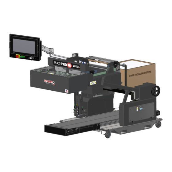
PREFIX The MAX™ PRO 18© Continuous Bagging System, redesigned from the ground up for increased productivity © and easier operation. The MAX™ PRO 18 is an effective solution for manually bagging product, dramatically © reducing packaging costs and improving package quality. The MAX™ PRO 18 platform features an integrated ZT610 Zebra pivoting printhead. -
Page 5: General Information
INTRODUCTION GENERAL INFORMATION ABOUT THIS MANUAL © This manual has been prepared for your use in operating model 1174-02 of the Sharp MAX™ PRO 18 Contin- uous Bagging System. Images and instructions may differ slightly for older models, but basic function is the same. -
Page 6: Safety Rules & Procedures
SECTION 1 - INTRODUC- SAFETY RULES & PROCEDURES The machine requires regular, periodic maintenance to ensure reliable service. No maintenance should be per- formed unless the safety precautions for maintenance are thoroughly understood. • Follow all instructions in this manual for safe operation. •... -
Page 7: Equipment Safety Features
SECTION 1 - INTRODUC- EQUIPMENT SAFETY FEATURES MACHINE GUARDS WARNING! © The Sharp MAX™ PRO 18 is equipped with guards covering the heated sealing area and the underside of © The Sharp MAX™ PRO 18 is equipped with the Head Assembly. DO NOT operate the MAX™ Jaw Obstruction Detection Sensors. -
Page 8: Safety Labels
SECTION 1 - INTRODUC- EQUIPMENT SAFETY FEATURES Risk Of Fire SAFETY LABELS Side Crush And Burn Hazard The following label is located in the proximity of a fused circuit. Be certain to replace blown fuses ONLY © with fuses with the same electrical rating. Always dis- This label is placed onto the Sharp MAX™... -
Page 9: Specifications
Phone: +1 (262) 246-8815 (ext. 1572) E-mail: sharpservice@pregis.com MAX18-19L-1174-02-XXX SERVICE INFORMATION DECAL The serial number can be found on the Service Infor- mation Decal located on the side of the bagger. -
Page 10: Machine Dimensions
SECTION 1 - INTRODUC- MACHINE DIMENSIONS FRONT VIEW Bagger dimensions viewed from front. Measurements are in inches. 56.5” 34.4” 33.4” © MAX PRO 18 Operator Manual Original Printed in English... -
Page 11: Top View
SECTION 1 - INTRODUC- MACHINE DIMENSIONS TOP VIEW Bagger dimensions viewed from top. Measurements are in inches. 42.8” 74.9 © MAX PRO 18 Operator Manual Original Printed in English... -
Page 12: Side View
SECTION 1 - INTRODUC- MACHINE DIMENSIONS SIDE VIEW Bagger dimensions viewed from side. Measurements are in inches. 38.3” 36.1” 76.4” © MAX PRO 18 Operator Manual Original Printed in English... -
Page 13: Sharp Ez-Bags
SECTION 1 - INTRODUC- © SHARP EZ-BAGS & RIBBON THERMAL TRANSFER RIBBON © The Sharp MAX™ PRO 18 is designed to use a wide © variety of bag sized and materials. Sharp EZ-Bags © The Sharp MAX™ PRO 18 uses thermal transfer are recommended for optimum operating perfor- ribbon to print various information onto the bags as mance, efficiency and safety. -
Page 14: Section 2 - Controls
SECTION 3 - CONTROLS SECURITY The ‘Technician’, ‘Field Service’, and ‘Manufacturing’ icons are password protected. Pressing any of these three icons will prompt user to type in a password. The ‘Operator’ and ‘Support’ icons are not password protected. NOTE: See Supervisor or Manager for correct password for each icon. ©... -
Page 15: Home Screen
SECTION - CONTROLS SCREEN NAVIGATION HOME SCREEN This screen appears at machine start-up and by pressing the home button on bottom left corner of screen. Pressing any of the 5 large buttons on this screen, opens new screen. © MAX PRO 18 Operator Manual Original Printed in English... - Page 16 SECTION 2 - CONTROLS SCREEN NAVIGATION OPERATOR BUTTON Pressing the Operator Button from the Home Screen opens the Operator Dashboard Screen. This screen al- lows Operator to monitor bagger function. Access to this screen is not password protected. JOB DETAILS Pressing the Job Detail button opens a pop-up window with bag dimensions and bag feed speed.
- Page 17 SECTION 2 - CONTROLS SCREEN NAVIGATION OPERATOR DASHBOARD - CONTINUED PERFORMANCE Last Cycle Time: Displays the actual time of last completed cycle, in seconds. Average Cycle Time: The average cycle time all cycles, in seconds. Reset Average Cycle Time: Reset or clears the average cycle time. SEAL BAR TEMPERATURE Current: The current temperature of Seal Bar.
- Page 18 SECTION 2 - CONTROLS SCREEN NAVIGATION TECHNICIAN BUTTON Pressing the Technician Button from the Home Screen opens the Job Setup Screen. This screen allows a Us- er to configure Bag Dimensions and Feed Speed, Bag Opening, Package Eject, Pressure Bar and Seal Bar, Auxiliary Input/output and Printer.
-
Page 19: Job Setup Screen
SECTION 2 - CONTROLS SCREEN NAVIGATION JOB SETUP SCREEN - BAG DIMENSIONS AND FEED SPEED Any changes made to this screen requires operator to press ‘Load Job’ button. BAG DIMENSIONS Length: This refers to the usable area inside the bag. This is measured from the bottom of the bag to the seal. - Page 20 SECTION 2 - CONTROLS SCREEN NAVIGATION JOB SETUP SCREEN - BAG OPENING Any changes made to this screen requires operator to press ‘Load Job’ button. JAW PASS-THRU Pass-Thru: Sets Pass-thru, will change (move) once job is loaded. LOW PRESSURE AIR - Press box in middle to set timeout for LPA at end of cycle to hold bag open. Always OFF: Always OFF Always ON: Always ON HIGH PRESSURE AIR...
-
Page 21: Package Eject
SECTION 2 - CONTROLS SCREEN NAVIGATION JOB SETUP SCREEN - PACKAGE EJECT Any changes made to this screen requires operator to press ‘Load Job’ button. Bag Drop Time: Time for bag to drop before feeding new bag out. LPA Bag Eject Assist: Toggle switch turns LPA ON or OFF to assist the ejection of sealed bag. INTEGRATED EXIT CONVEYOR Runtime: Timeout for Integrated Exit Conveyor, starts when package starts to fall. -
Page 22: Seal Bar
SECTION 2 - CONTROLS SCREEN NAVIGATION JOB SETUP SCREEN - PRESSURE BAR AND SEAL BAR Any changes made to this screen requires operator to press ‘Load Job’ button. PRESSURE BAR Open Delay: Adjusts the delay, in seconds, that occurs prior to opening the Pressure Bar. Close Delay: Adjusts the delay, in seconds, that occurs prior to closing the Pressure Bar. - Page 23 SECTION 2 - CONTROLS SCREEN NAVIGATION JOB SETUP SCREEN - AUXILIARY INPUT/OUTPUT Any changes made to this screen requires operator to press ‘Load Job’ or ‘Save & Load’ button. INPUT Not Configured: No configuration. Bagger Inhibit: Will not allow bagger to cycle until input held low. Warning appears when this is active. OUTPUT 1 Not Configured: No configuration.
- Page 24 SECTION 2 - CONTROLS SCREEN NAVIGATION Any changes made to this screen requires operator to press ‘Load Job’ or ‘Save & Load’ button. OUTPUT 2 Not Configured: No configuration. Printer Data Ready: Output active when Printer is ready for a new label. Waiting For Printer: Machine is cycling and film is backed up and ready to print but printer needs label.
- Page 25 SECTION 2 - CONTROLS SCREEN NAVIGATION JOB SETUP SCREEN - PRINTER Any changes made to this screen requires operator to press ‘Load Job’ or ‘Save & Load’ button. PRINTER SETTINGS Speed: This numeric setting determines the web feed speed during the print cycle. It is adjustable from 2.00 to 12.00 Inches/Sec.
- Page 26 SECTION 2 - CONTROLS SCREEN NAVIGATION APPLICATION SCREEN Pressing the Settings Button icon on Left Menu Bar (When in password protected screen) will open the Appli- cations Settings page. Any changes made to this screen requires operator to press ‘Load Job’ or ‘Save & Load’ button. Application - This allows a User to select HMI Language and to activate Demo Mode.
- Page 27 SECTION 2 - CONTROLS SCREEN NAVIGATION FIELD SERVICE BUTTON Pressing the FIELD SERVICE button from the Home Screen opens the Service Screen. This screen display the Inputs and Outputs that are active (Highlighted Green) on PLC. This screen allows a User to manually trigger Bag Position, Bag Open Fingers, Integrated Exit Conveyor, Load Plate, Low-Pressure Air, High-Pressure Air, Pass-Thru, Pressure Bar, Printer, Seal Bar, Seal Flatteners and Vacuum.
- Page 28 SECTION 2 - CONTROLS SCREEN NAVIGATION SERVICE SCREEN - BAG Photo-Eye Covered: Green light indicates the Photo-eye detects bag. Reverse: Pressing Reverse button will reverse the web as long as button is pressed. Forward: Pressing Forward button will advance the web as long as button is pressed. BAGS MADE Total: Displays the total number of completed bags since last reset.
- Page 29 SECTION 2 - CONTROLS SCREEN NAVIGATION SERVICE SCREEN - BAG OPEN FINGERS FINGERS Grab: Activates the Bag Open Fingers. Fingers will Rotate down. Release: Fingers will Rotate up to release the bag. CYCLES Total: The total number of cycle the Bag Open Fingers have completed since last reset. OPEN RETRIES Total: The total number of times the Bag Open Fingers have attempted to open fed bag.
- Page 30 SECTION 2 - CONTROLS SCREEN NAVIGATION SERVICE SCREEN - INTEGRATED EXIT CONVEYOR. Start: Pressing this button will turn the Conveyor ON. Press button again to stop. JOG DWELL Dwell: Time that conveyor will run. Jog Sec.: Press and hold to run exit conveyor until released. This will change the Dwell. Apply To Settings: Time that jog was pressed can be set to job dwell setting.
- Page 31 SECTION 2 - CONTROLS SCREEN NAVIGATION SERVICE SCREEN - LOAD PLATE To Discharge: Moves the Load Plate to the ‘Discharge’ position. To Load: Moves the Load Plate to the ‘Load’ Position. CYCLES Total: Displays the total number of complete Load Plate cycles since last reset. Reset Counter: Reset the Cycle Total Counter.
- Page 32 SECTION 2 - CONTROLS SCREEN NAVIGATION SERVICE SCREEN - LOW/HIGH PRESSURE AIR LOW PRESSURE AIR Start: Pressing this button turns Low Pressure Air ON. Press again to turn OFF. Dwell: The amount of time the Low Pressure Air will be ON according to setting in loaded job. Current: The actual setting of Low Pressure Air blast.
- Page 33 SECTION 2 - CONTROLS SCREEN NAVIGATION SERVICE SCREEN - PASS-THRU Distance: The current Pass-thru distance. Jog IN: Moves Jaw inward as long as button is pushed or until it reaches Face Plate. Jog OUT: Moves Jaw outward as long as button is pushed or until it reaches end of travel. MANUAL POSITION Current: The actual width of Jaw.
- Page 34 SECTION 2 - CONTROLS SCREEN NAVIGATION SERVICE SCREEN - PRESSURE BAR Move IN: Pressing this button will retract or close the Pressure Bar. Pressure Bar will remained closed until Move OUT is pushed. Move OUT: Pressing this button will extend or open the Pressure Bar. CYCLES Total: Total number of Cycles the Pressure Jaw has completed since last reset.
- Page 35 SECTION 2 - CONTROLS SCREEN NAVIGATION SERVICE SCREEN - PRINTER Online: When lit, printer is on and ready for label. Pause: The Pause key temporarily suspends printing. Pressing the key again will return the printer to normal operation. Reset: Clears printer faults. Raise Printhead: Press to raise Printhead.
- Page 36 SECTION 2 - CONTROLS SCREEN NAVIGATION SERVICE SCREEN - SEAL BAR Move IN: Pressing button will retract Seal Bar. Move OUT: Pressing button will extend Seal Bar. Seal Bar will remain out until Move IN button is pressed. CYCLE Current: Displays the length of time Seal Bar is active. Pulse Sec.: Cycles the Seal Bar.
-
Page 37: Seal Flatteners
SECTION 2 - CONTROLS SCREEN NAVIGATION SERVICE SCREEN - SEAL FLATTENERS Raise: Pressing button raised the Seal Flattener Fingers. Lower: Pressing button lowers the Seal Flattener Fingers. DISTANCE FROM CENTER The distance that fingers are from the center of sealing area. Jog IN: Moves fingers IN as long as button is pressed or until fingers reach center. -
Page 38: Vacuum
SECTION 2 - CONTROLS SCREEN NAVIGATION SERVICE SCREEN - VACUUM Start: Turns on Vacuum. Vacuum will stay on until button is pressed again. DWELL Current: The actual setting of the Vacuum ON. Pulse Sec.: Pressing the button will turn Vacuum ON for length of Dwell Setting. Setting: The actual length of Vacuum on when button is pushed. -
Page 39: Support Screen
SECTION 2 - CONTROLS SCREEN NAVIGATION SUPPORT SCREEN SUPPORT CONTACT - Provides the contact information for Sharp Service and Sharp Parts. Also provides Sharp Packaging Systems mailing address. SOFTWARE VERSIONS - Displays current Software. Upgrade From File: Allows for mapping to saved HMI program file used to upgrade program. ©... -
Page 40: Section 3 - Set-Up & Operation
SECTION 3 - SET-UP & OPERATION MACHINE PLACEMENT and grounded in the accordance with all local codes ELECTRICAL PRECAUTIONS and ordinances. Do not modify the plug provided with the machine. If your electrical supply does not meet the above specifications, or if you are unsure your building has an effective ground, have a qualified electrician or your local electrical utility company check the ground and correct any problems. - Page 41 SECTION 3 - SET-UP & OPERATION MACHINE PLACEMENT 4. Turn the switch on the Power Entry Module to ON POWER CONNECTION position. © The Sharp MAX™ PRO 18 is equipped with a 3- 5. Plug the Male End of second Power Cord into a prong electrical cord for standard, properly grounded, properly grounded wall outlet or electrical drop.
-
Page 42: Air Supply
SECTION 3 - SET-UP & OPERATION MACHINE ADJUSTMENTS AIR SUPPLY HEIGHT ADJUSTMENT © The Sharp MAX™ PRO 18 has a filter/regulator Machine height can be adjusted to allow manual load- equipped with a male end 1/4” nominal flow NPT air ing at a convenient height. -
Page 43: Load Plate
SECTION 3 - SET-UP & OPERATION MACHINE ADJUSTMENTS HEAD ROTATION - CONTINUED LOAD SHELF The Load Shelf can be moved up or down to accom- modate different sized bags. 1. Loosen the Locking Handles on back of Load Plate. 1. Loosen the Rotating Clamp Screws. 2. -
Page 44: Loading Bag Film
SECTION 3 - SET-UP & OPERATION LOADING BAG FILM Then under-over Unwind Drag Tubes, then under A decal showing the film threading path through the Idler Roller, finally over the Unwind Drive Roller. machine is located on the Frame Cover. Close Unwind Cradle Latch. - Page 45 SECTION 3 - SET-UP & OPERATION LOADING BAG FILM Pull the film Under the Printer Carriage until edge drapes over the Platen and Drive Rollers and down past the Front Finger Plate. 5. Lower and lock the Drive Roller Cradle Latch. ©...
-
Page 46: Loading Ribbon
SECTION 3 - SET-UP & OPERATION LOADING RIBBON A decal showing the ribbon threading path is located on the inside of Carriage Cover. 1. Raise the Carriage Cradle and Open Carriage 6. Place empty cardboard roll onto Ribbon Rewind Cover. Hub. -
Page 47: Operation
SECTION 3 - SET-UP & OPERATION OPERATION 9. Press the ‘Operator’ button to open Operator Before attempting to operate the machine, read all Screen. information under Equipment Safety Features, page 1- 2 and Controls, page 3-1. 10. Press the ‘Job Search’ and select job to be load- Load film material as illustrated in Web Threading Dia- gram on machine. -
Page 48: Cleaning Guidelines
SECTION 3 - SET-UP & OPERATION CLEANING hered to without exception. GENERAL CLEANING GUIDELINES Inspect the machine to determine if there has been an This machine requires regular, periodic cleaning to accumulation of dust or other contaminations. Clean if ensure reliable service. The Operator, with a minimum necessary. -
Page 49: Cleaning / Maintenance Intervals
SECTION 3 - SET-UP & OPERATION CLEANING / MAINTENANCE INTERVALS • Inspect the Air Filter for debris and replace as DAILY CLEANING / MAINTENANCE necessary. • Inspect the Bag Edge Present Sensor. Clean • Inspect all external wiring for loose connec- as needed. - Page 50 SECTION 3 - SET-UP & OPERATION CLEANING PRINTHEAD BAG EDGE PRESENT SENSOR 1. Turn the Printer Control Box OFF. 1. Remove Power from bagger. 2. Open the Printer Carriage by releasing the Draw Latch on side of Printer Carriage. 2. Clean with a cotton swab if dirty. Do not use any solvents or cleaning solutions on the sensing por- 3.
- Page 51 SECTION 3 - SET-UP & OPERATION CLEANING 6. When rollers are clean, close the Cradle Latch. DRIVE & PLATEN ROLLERS 7. Return power and air to bagger. Regular cleaning of the Drive & Platen Rollers will keep the Sharp MAX™ PRO 18 running at optimum PINCH ROLLER performance.
- Page 52 SECTION 3 - SET-UP & OPERATION CLEANING SEAL BAR 6. NEVER use any metallic utensils on the surface The Seal Bar needs extended to complete this proce- of Seal Bar. Use the Cleaning Wand (Sharp P/N dure. In order to do this, the machine needs power 704173-01) to remove any residue accumulated and air.
- Page 53 SECTION 3 - SET-UP & OPERATION CLEANING PINCH ROLLER UNWIND DRIVE ROLLER After Cleaning the Unwind Drive Roller, clean the Un- Regular cleaning of the Unwind Drive & Pinch Rollers wind Pinch Roller in the Latch Assembly. will keep the Sharp MAX™ PRO 18 running at opti- mum performance.
- Page 54 FAULT & ALERT MANAGEMENT BAGGER FAULTS Fault Cause Possible Solution (S) Pressure Bar Obstruction The Pressure Bar attempted to This is usually a part that did not close, but was blocked by an ob- drop past the Pressure Bar. In- struction.
- Page 55 FAULT & ALERT MANAGEMENT BAGGER FAULTS Fault Cause Possible Solution (S) Bag Failed To Open The Bag Opened Sensor failed to This fault is usually the result of a make as the Bag Open Fingers problem with the Pressure Bar Pass were attempting to open the bag.
- Page 56 FAULT & ALERT MANAGEMENT BAGGER/PRINTER WARNINGS Fault Cause Possible Solution (S) Seal Bar not at Temperature - Seal Bar is not at the required tem- Bagger will not cycle until required Bagger inhibited from cycling perature for sealing. temperature has been reached. Low Pressure Air Timed Out Low Pressure Air Timed Out No intervention required by opera-...
- Page 57 FAULT & ALERT MANAGEMENT PRINTER FAULTS All printer functions are internally monitored. When a problem (Fault) or a potential problem (Warning) is detect- ed, a corresponding message will appear in the display. Fault messages receive the highest display priority. If more the one fault is detected the display will cycle between messages.
-
Page 58: Printer Troubleshooting
FAULT & ALERT MANAGEMENT PRINTER TROUBLESHOOTING Barcode Does Not Scan Issue Possible Cause Possible Solution (s) The barcode printed on label 1. Print a test label. The barcode is not within specifi- does not scan. 2. If necessary, manually adjust cations because the printer is set the darkness or print speed at an incorrect darkness level. - Page 59 FAULT & ALERT MANAGEMENT PRINTER TROUBLESHOOTING Angled Gray Lines on Blank Labels Issue Possible Cause Possible Solution (s) Fine, angular gray lines on Wrinkled ribbon. Verify the ribbon is loaded properly, blank labels smooth out ribbon. Missing Print Issue Possible Cause Possible Solution (s) Long tracks of missing print on Print element damaged.
-
Page 60: Appendix
APPENDIX WARRANTY SHARP PACKAGING SYSTEMS ("SHARP") STANDARD TERMS AND CONDITIONS FOR PACKAGING MACHINERY By placing an order, Buyer agrees to the following terms and conditions: TERMS OF PAYMENT: Cash in lawful U.S. currency payable as follows: For base machinery w/o automatic in-feed devices, (2/3) of net price with the order and the final (1/3) of net price within thirty (30) days after shipment.
Need help?
Do you have a question about the SHARP MAX PRO 18 and is the answer not in the manual?
Questions and answers
Bagger continues to cycle bags despite printer ribbon running out, resulting in bags printed with nothing on them.