Table of Contents
Advertisement
Quick Links
Advertisement
Table of Contents

Subscribe to Our Youtube Channel
Related Manuals for Sunny Health & Fitness SF-E3981


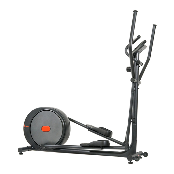
Summary of Contents for Sunny Health & Fitness SF-E3981
- Page 1 CARBON PRO MAGNETIC ELLIPTICAL SF-E3981 USER MANUAL IMPORTANT! Please retain owner’s manual for maintenance and adjustment instructions. Your satisfaction is very important to us, PLEASE DO NOT RETURN UNTIL YOU HAVE CONTACTED US: support@sunnyhealthfitness.com or 1- 877 - 90SUNNY (877-907-8669).
-
Page 2: Important Safety Information
IMPORTANT SAFETY INFORMATION We thank you for choosing our product. To ensure your safety and health, please use this equipment correctly. It is important to read this entire manual before assembling and using the equipment. Safe and effective use can only be achieved if the equipment is assembled, maintained, and used properly. -
Page 3: Exploded Diagram
EXPLODED DIAGRAM 1 11 13 35 36 51 50... - Page 4 EXPLODED DIAGRAM 2...
-
Page 5: Parts List
PARTS LIST Description Spec. Qty. Description Spec. Qty. Computer Washer d6*Φ16*1.5 Computer Wire 1 Front Stabilizer Computer Wire 2 Bolt M8*42*15*S5 Trunk Wire Transportation Wheel Upright Post Washer d8*Φ16*1.5 Middle Handlebar Nylon Nut M8*H7.5*S13 Foam Grip Φ23*3*350 Bolt M8*73*20*H5 Handle Pulse Cap Nut M8*H16*S13 Plate 1... -
Page 6: Hardware Package
Description Spec. Qty. Description Spec. Qty. Middle Axle Washer d12*Φ17*0.5 Nylon Nut M6*H6*S10 Idler Wheel Shaft Spring Washer Wave Washer Bolt M6*16*S10 Bearing 6001 Belt Wheel Φ260 Idler Wheel Belt 6PJ380 Washer d6*Φ16 Round Magnet Bolt M6*12*S10 Sensor Wire Nylon Nut M8*H7.5*S13 Screw ST4.2*16... - Page 7 ASSEMBLY INSTRUCTIONS We value your experience using Sunny Health and Fitness products. For assistance with parts or troubleshooting, please contact us at support@sunnyhealthfitness.com or 1-877-90SUNNY (877-907-8669). STEP 1: #38 M8*H16*S13 4PCS #13 d8 4PCS Remove 4 Bolts (No. 37), 4 Arc Washers #37 M8*73*20*H5 4PCS (No.
- Page 8 We value your experience using Sunny Health and Fitness products. For assistance with parts or troubleshooting, please contact us at support@sunnyhealthfitness.com or 1-877-90SUNNY (877-907-8669). STEP 2: Remove 6 Bolts (No. 11), 6 Spring #13 d8 8PCS #20 M8*19*S14 2PCS Washers (No. 13), and 6 Arc Washers #21 d8*Φ32*2 2PCS (No.
- Page 9 We value your experience using Sunny Health and Fitness products. For assistance with parts or troubleshooting, please contact us at support@sunnyhealthfitness.com or 1-877-90SUNNY (877-907-8669). STEP 3: Attach Left & Right Handlebars (No. 17L/R) to Left & Right Swing Rods (No. 26L/R) using 4 Bolts (No.
- Page 10 We value your experience using Sunny Health and Fitness products. For assistance with parts or troubleshooting, please contact us at support@sunnyhealthfitness.com or 1-877-90SUNNY (877-907-8669). STEP 4: #78 M5*10 4PCS Remove 2 Bolts (No. 11), 2 Arc Washers #13 d8 2PCS (No.
-
Page 11: Battery Installation And Replacement
BATTERY INSTALLATION & REPLACEMENT Battery Cover Battery BATTERY INSTALLATION 1. Take out 2 AAA batteries from computer box. 2. Press the buckle of battery cover on the Computer (No. 1), then remove battery cover. 3. Install 2 AAA batteries into the battery case on the back of the Computer (No. 1). Pay attention to the battery + and - poles before installing. -
Page 12: Exercise Computer
EXERCISE COMPUTER WINDOW DISPLAY 1) Main window: SPEED/RPM; 2) TIME, DIS. (DISTANCE), CAL. (CALORIE), PULSE window; KEY FUNCTION MODE: 1) During use: press MODE button to switch main window between SPEED and RPM; 2) During inactivity: press MODE button to enter the Setting Mode and choose functions to set value. - Page 13 ADJUSTMENTS & USAGE GUIDE ADJUSTING THE TENSION Rotate the Tension Control Knob (No. 44) clockwise to increase the level of resistance. Rotate the Tension Control Knob (No. 44) counter-clockwise to decrease the level of resistance. Tension levels are set at Level 1 being the lowest and Level 10 being the highest.
-
Page 14: Troubleshooting
TROUBLESHOOTING PROBLEM SOLUTION 1. Remove the computer and verify that the wires from computer properly connected to the wires that come from the upright post. There is no display on the computer. 2. Check if the batteries are correctly positioned and that the battery springs are in proper contact with batteries.
Need help?
Do you have a question about the SF-E3981 and is the answer not in the manual?
Questions and answers