Advertisement
Advertisement
Table of Contents

Subscribe to Our Youtube Channel
Summary of Contents for Hyster C108
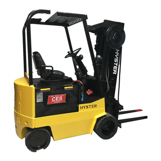
- Page 1 Hyster C108 (E40XL, E50XL, E55XL, E60XL) Electric Forklift...
- Page 2 STEERING SYSTEM FOR ELECTRIC LIFT TRUCKS A1.00-1.50XL (A20-30XL) [A203]; J2.00-3.00XL (J40-60XL) [B168]; E1.25-1.75XL (E25-35XL) [C114]; E2.00-3.00XL (E40-60XL) [C108]; E3.50-5.50XL (E70-120XL, E70-120XL ) [C098]; E1.50-2.00XMS (E25-40XMS, E25-40XM S) [D114]; E2.00-3.20XM (E45-65XM, E45-65XM ) [F108]; J2.00-3.20XM (J40-60XM, J40-60XM ) [A216]; N30XMH, N30XM H [A210, C210] PART NO.
- Page 3 • Use the correct tools for the job. • Keep the tools clean and in good condition. • Always use HYSTER APPROVED parts when making repairs. Replacement parts must meet or exceed the specifications of the original equipment manufacturer. • Make sure all nuts, bolts, snap rings, and other fastening devices are removed before using force to remove parts.
-
Page 4: Table Of Contents
Optical Encoder and Activator Circuits Check ....................Troubleshooting..............................This section is for the following models: A1.00-1.50XL (A20-30XL) [A203]; J2.00-3.00XL (J40-60XL) [B168]; E1.25-1.75XL (E25-35XL) [C114]; E2.00-3.00XL (E40-60XL) [C108]; E3.50-5.50XL (E70-120XL, E70-120XL ) [C098]; E1.50-2.00XMS (E25-40XMS, E25-40XM S) [D114]; E2.00-3.20XM (E45-65XM, E45-65XM ) [F108];... - Page 5 Thanks very much for your reading, Want to get more information, Please click here, Then get the complete manual NOTE: If there is no response to click on the link above, please download the PDF document first, and then click on it. Have any questions please write to me: admin@servicemanualperfect.com...
- Page 6 "THE QUALITY KEEPERS" HYSTER APPROVED PARTS...
-
Page 7: General
1600 SRM 485 General General There are two different steering systems available: 630 SRM 363 which contains the description and Power Steering and Power Steering with On-De- repair of the MDU for the A1.00-1.5.XL (A20-30XL), mand. The difference in the components for each the Steering Axle for your unit, and the Steering system can be found in Figure 1 and Figure 2. - Page 8 General 1600 SRM 485 Figure 2. Power Steering Components E1.50-2.00XMS (E25-40XMS, E25-40XM...
-
Page 9: Description
1600 SRM 485 Description Legend for Figure 2 1. STEERING CYLINDER 6. PRESSURE SWITCH (ON-DEMAND STEERING 2. TO STEERING CONTROL UNIT ONLY) 3. PRESSURE CHECK FITTING 7. RETURN TO HYDRAULIC TANK 4. PUMP MOTOR 8. FROM HYDRAULIC TANK 5. STEERING PUMP 9. -
Page 10: Steering Wheel And Column Assembly Repair
Steering Wheel and Column Assembly Repair 1600 SRM 485 A gear on the shaft of the steering wheel drives the the battery negative circuit for the steering contactor gear of the optical encoder as the steering wheel is to energize the steering pump motor. The steering moved to steer the lift truck. - Page 11 1600 SRM 485 Steering Wheel and Column Assembly Repair Figure 4. Steering Wheel and Steering Column Assembly (Early XL Units)
- Page 12 Steering Wheel and Column Assembly Repair 1600 SRM 485 Legend for Figure 4 NOTE: FOR CORRECT CONNECTION, SEE THE DIAGRAMS SRM FOR YOUR LIFT TRUCK. A. DANFOSS B. TRW 1. TRUCK WIRE HARNESS 11. LATCH 2. SNAP RING 12. BRACKET 3.
- Page 13 1600 SRM 485 Steering Wheel and Column Assembly Repair NOTE: PETRI STEERING WHEEL SHOWN. 1. LATCH PIVOT PIN 10. SOCKET HEAD SCREW 19. PLASTIC WASHER 2. COTTER PIN 11. ADJUSTER SPOOL NUT 20. SPRING 3. BRACKET 12. HORN COVER 21. BRACKET 4.
- Page 14 Steering Wheel and Column Assembly Repair 1600 SRM 485 Figure 6. Steering Wheel and Steering Column Assembly (Early Model XM Units)
-
Page 15: Assembly Components, Install
1600 SRM 485 Steering Wheel and Column Assembly Repair Legend for Figure 6 NOTE: FOR CORRECT CONNECTION, SEE THE DIAGRAMS SRM FOR YOUR LIFT TRUCK. 1. STEERING WHEEL, SHAFT, AND ON-DEMAND 13. PLATE STEERING PARTS 14. ALLEN HEAD CAPSCREW 2. STEERING CONTROL UNIT 15. - Page 16 Steering Wheel and Column Assembly Repair 1600 SRM 485 Figure 7. Steering Wheel and Steering Column Assembly (Later Model XM Units)
- Page 17 1600 SRM 485 Steering Wheel and Column Assembly Repair Legend for Figure 7 1. ON-DEMAND STEERING COMPONENTS 17. COTTER PIN 2. FRONT COVER 18. PIN 3. BRACKET 19. STEERING CONTROL UNIT 4. PIVOT (STEERING) SHAFT 20. PLUG (WITHOUT TURN SIGNAL) 5.
-
Page 18: Power Steering Motor And Pump
Power Steering Motor and Pump 1600 SRM 485 Power Steering Motor and Pump DESCRIPTION E1.50-2.00XMS (E25-40XMS, E25-40XM S) and the E3.50-5.50XL (E70-120XL, E70-120XL ) units NOTE: See the section Hydraulic System for your have the motor and pump assembly under the bat- lift truck model for additional information on the tery compartment. - Page 19 1600 SRM 485 Power Steering Motor and Pump 1. LIFT TRUCK FRAME 7. FROM HYDRAULIC TANK 2. STEERING MOTOR 8. TO STEERING CONTROL UNIT 3. STEERING PUMP 9. PUMP MOUNTING BOLT 4. O-RING 10. BRACKET MOUNTING BOLT 5. MOUNTING BRACKET 11.
-
Page 20: Remove
Power Steering Motor and Pump 1600 SRM 485 1. MOTOR 6. MOUNT BRACKET 2. HYDRAULIC PUMP - STEERING 7. FRAME BRACKET 3. WASHER 8. MOUNT PIN 4. RUBBER BUSHINGS 9. MOTOR BASE 5. CAPSCREW AND NUT Figure 10. Power Steering Pump Motor E1.50-2.00XMS (E25-40XMS, E25-40XM REMOVE AND DISASSEMBLE, MODELS 5. - Page 21 1600 SRM 485 Power Steering Motor and Pump 1. THROUGH BOLT 14. INSULATOR WASHER 2. END PLATE 15. WASHER 3. SPRING WASHER 16. WASHER 4. BEARING 17. NUT 5. BRUSH HOLDER MOUNT SCREW 18. STATOR 6. BRUSH HOLDER ASSEMBLY 19. COVER 7.


Need help?
Do you have a question about the C108 and is the answer not in the manual?
Questions and answers