Table of Contents
Advertisement
Quick Links
Advertisement
Table of Contents
Troubleshooting

Subscribe to Our Youtube Channel
Related Manuals for Rohde & Schwarz ESW


Summary of Contents for Rohde & Schwarz ESW
- Page 1 ® R&S EMI Test Receiver User Manual (;ÛÌð2) 1177629802 Version 13...
- Page 2 Rohde & Schwarz GmbH & Co. KG. Trade names are trademarks of the owners. ® 1177.6298.02 | Version 13 | R&S Throughout this manual, products from Rohde & Schwarz are indicated without the ® symbol , e.g. R&S ® ESW is indicated as R&S ESW.
-
Page 3: Table Of Contents
Setting up the product....................25 4.4.1 Placing the product on a bench top................25 4.4.2 Mounting the R&S ESW in a rack................. 26 Connecting the AC power..................27 Switching the instrument on and off................. 27 Connecting to LAN......................28 Connecting a keyboard....................29... - Page 4 LAN connector......................49 5.2.5 USB ports........................49 5.2.6 IF / video / demod output....................49 5.2.7 Sync trigger input and output..................49 5.2.8 GPIB interface.......................49 5.2.9 Aux. port........................50 5.2.10 External generator control option (R&S ESW-B10)............50 5.2.11 OCXO (optional)......................50 User Manual 1177.6298.02 ─ 13...
- Page 5 ® Contents R&S 5.2.12 REF INPUT / REF OUTPUT..................50 5.2.13 Labels on R&S ESW..................... 51 5.2.14 Device ID........................51 6 Operating the instrument..............53 Understanding the display information..............53 6.1.1 Channel bar........................54 6.1.2 Window title bar......................56 6.1.3 Marker information......................57 6.1.4...
- Page 6 ® Contents R&S Available Applications....................81 Starting an Application....................83 Running a sequence of measurements..............84 7.4.1 The sequencer concept....................84 7.4.2 Sequencer settings....................... 87 7.4.3 How to set up the sequencer..................87 8 Measurements and result displays............ 89 Performing measurements..................89 Bargraph configuration....................91 Test automation......................96 8.3.1 Background information....................
- Page 7 ® Contents R&S 9.7.2 Amplitude settings.......................194 9.7.3 Diagram scale......................196 9.7.4 Preselector........................197 Frequency and span configuration................. 197 9.8.1 Impact of the frequency and span settings..............197 9.8.2 Frequency and span settings..................200 Bandwidth and Filter Configuration................ 204 9.9.1 Impact of Bandwidth and Filter Settings..............205 9.9.2 Bandwidth and Filter Settings..................
- Page 8 ® Contents R&S 10.5.1 Display lines........................ 264 10.5.2 Limit lines........................266 11 Data management................283 11.1 Restoring the default instrument configuration (preset)........283 11.2 Protecting data using the secure user mode............284 11.3 Storing and recalling instrument settings and measurement data...... 286 11.3.1 Quick save/quick recall....................
- Page 9 ® Contents R&S 12.4 Transducers.......................355 12.4.1 Transducer........................355 12.4.2 Working with transducers.................... 356 12.4.3 Reference: transducer factor file format..............366 12.4.4 How to configure the transducer................. 366 12.5 Reference frequency settings..................370 12.6 System configuration settings.................374 12.6.1 Hardware information....................374 12.6.2 Information on versions and options................375 12.6.3 System messages.......................376 12.6.4...
- Page 10 How to log on to the network..................437 13.6.4 How to share directories (only with microsoft networks)..........439 13.6.5 How to control the R&S ESW via the web browser interface........440 13.6.6 How to deactivate the web browser interface............. 441 13.6.7 How to set up remote desktop..................442 13.6.8...
- Page 11 ® Contents R&S 14.5.12 CISPR APD measurement configuration..............503 14.5.13 Programming example: performing a sequence of measurements......504 14.6 Configuration......................506 14.6.1 Input configuration.......................506 14.6.2 Output configuration....................532 14.6.3 Frequency configuration....................540 14.6.4 Amplitude configuration....................544 14.6.5 Diagram scale......................547 14.6.6 Bandwidth and filter configuration................548 14.6.7 Trigger configuration....................
- Page 12 ® Contents R&S 14.9.8 System configuration check..................711 14.9.9 Service functions......................718 14.10 Using the status register..................720 14.10.1 General status register commands................720 14.10.2 Reading out the CONDition part................. 721 14.10.3 Reading out the EVENt part..................722 14.10.4 Controlling the ENABle part..................722 14.10.5 Controlling the negative transition part................723 14.10.6...
- Page 13 ® Contents R&S 15.3 Transporting......................767 15.4 Disposal........................768 16 Troubleshooting................. 769 16.1 Error information.......................769 16.2 Error messages in remote control mode..............770 16.3 Troubleshooting remote operation................771 16.4 Miscellaneous troubleshooting hints..............773 16.5 System recovery....................... 774 16.6 Collecting information for support................775 16.7 Contacting customer support..................777 List of commands................
- Page 14 ® Contents R&S User Manual 1177.6298.02 ─ 13...
-
Page 15: Preface
1.1 About This Manual This user manual describes general instrument functions and settings common to all applications and operating modes in the R&S ESW. Furthermore, it provides all the information specific to EMI measurements in the receiver application. All other operating modes and applications are described in the specific application manuals. -
Page 16: Conventions Used In The Documentation
® Preface R&S Conventions used in the documentation ● List of commands Alphabetical list of all remote commands described in the manual ● Index 1.2 Conventions used in the documentation 1.2.1 Typographical conventions The following text markers are used throughout this documentation: Convention Description "Graphical user interface ele-... - Page 17 ® Preface R&S Conventions used in the documentation The screenshots usually show a fully equipped product, that is: with all options instal- led. Thus, some functions shown in the screenshots may not be available in your par- ticular product configuration. User Manual 1177.6298.02 ─...
-
Page 18: Safety And Regulatory Information
® Safety and regulatory information R&S Safety Instructions 2 Safety and regulatory information The product documentation helps you use the product safely and efficiently. Follow the instructions provided here and in the following chapters. Intended use The product is intended for the development, production and verification of electronic components and devices in industrial, administrative, and laboratory environments. - Page 19 ® Safety and regulatory information R&S Safety Instructions move or carry the product. Do not lift by the accessories mounted on the product. Accessories are not designed to carry the weight of the product. To move the product safely, you can use lifting or transporting equipment such as lift trucks and forklifts.
- Page 20 ® Safety and regulatory information R&S Safety Instructions ● Only use intact cables and route them carefully so that they cannot be damaged. Check the power cables regularly to ensure that they are undamaged. Also ensure that nobody can trip over loose cables. ●...
-
Page 21: Warning Messages In The Documentation
® Safety and regulatory information R&S Korea certification class B 2.2 Warning messages in the documentation A warning message points out a risk or danger that you need to be aware of. The sig- nal word indicates the severity of the safety hazard and how likely it will occur if you do not follow the safety precautions. -
Page 22: Documentation Overview
3.1 Getting started manual Introduces the R&S ESW and describes how to set up and start working with the prod- uct. Includes basic operations, typical measurement examples, and general informa- tion, e.g. safety instructions, etc. -
Page 23: Instrument Security Procedures
Application notes, application cards, white papers, etc. https://gloris.rohde-schwarz.com 3.4 Instrument security procedures Deals with security issues when working with the R&S ESW in secure areas. It is avail- able for download on the Internet. 3.5 Basic safety instructions Contains safety instructions, operating conditions and further important information. -
Page 24: Preparing For Use
"Lifting and carrying the product" on page 18. 4.2 Unpacking and checking 1. Unpack the R&S ESW carefully. 2. Retain the original packing material. Use it when transporting or shipping the R&S ESW later. 3. Using the delivery notes, check the equipment for completeness. -
Page 25: Setting Up The Product
® Preparing for use R&S Setting up the product See also "Choosing the operating site" on page 19. Electromagnetic compatibility classes The electromagnetic compatibility (EMC) class indicates where you can operate the product. The EMC class of the product is given in the data sheet under "General data". ●... -
Page 26: Mounting The R&S Esw In A Rack
2. Lift the R&S ESW to shelf height. 3. Grab the handles and push the R&S ESW onto the shelf until the rack brackets fit closely to the rack. 4. Tighten all screws in the rack brackets with a tightening torque of 1.2 Nm to secure the R&S ESW in the rack. -
Page 27: Connecting The Ac Power
1. Loosen the screws at the rack brackets. 2. Remove the R&S ESW from the rack. 3. If placing the R&S ESW on a bench top again, unmount the adapter kit from the R&S ESW. Follow the instructions provided with the adapter kit. -
Page 28: Connecting To Lan
The operating system shuts down. The LED changes to orange. If the instrument temperature exceeds the limit specified in the data sheet, the R&S ESW automatically shuts down to protect the instrument from damage. To disconnect from power The R&S ESW is in the standby state. -
Page 29: Connecting A Keyboard
Changing IP addresses ● Exchanging hardware Errors can affect the entire network. Connect the R&S ESW to the LAN via the LAN interface on the rear panel of the instrument. Windows automatically detects the network connection and activates the required drivers. -
Page 30: Connecting An External Monitor
48). Screen resolution and format The touchscreen of the R&S ESW is calibrated for a 16:10 format. If you connect a monitor or projector using a different format (e.g. 4:3), the calibration is not correct and the screen does not react to your touch actions properly. -
Page 31: Windows Operating System
After the R&S ESW is started, the operating system boots and the instrument firmware is started automati- cally. - Page 32 ® Preparing for use R&S Windows operating system You can install additional software on the instrument; however, additional software can impair instrument function. Thus, run only programs that Rohde & Schwarz has tested for compatibility with the instrument software. The following program packages have been tested: ●...
-
Page 33: Logging On
4.11 Logging on Microsoft Windows requires that users identify themselves by entering a user name and password in a login window. By default, the R&S ESW provides the following user accounts: ● "Instrument": an administrator account with unrestricted access to the computer/ domain ●... -
Page 34: Checking The Supplied Options
If you change the password that is used during auto-login, this function no longer works. Adapt the settings for the auto-login function first. 1. Select the "Windows" icon in the toolbar to access the operating system of the R&S ESW (see also "To access the "Start" menu" on page 32). -
Page 35: Performing A Self-Alignment
4. Check the availability of the hardware options as indicated in the delivery note. 4.13 Performing a self-alignment When strong temperature changes occur in the environment of the R&S ESW, or after updating the firmware, you have to perform a self-alignment to align the data to a refer- ence source. -
Page 36: Protecting Data Using The Secure User Mode
0 dB attenuation when measuring unknown signals can damage or destroy the input mixer. 4.15 Protecting data using the secure user mode During normal operation, the R&S ESW uses a solid-state drive to store its operating system, instrument firmware, instrument self-alignment data, and any user data cre- ated during operation. - Page 37 Storing required data permanently Any data that is to be available for subsequent sessions with the R&S ESW must be stored on the instrument permanently, before activating the secure user mode. This includes predefined instrument settings, transducer factors and self-alignment data.
- Page 38 "SecureUser Mode" on page 380). Remote control Initially after installation of the R&S ESW-K33 option, secure user mode must be enabled manually once before remote control is possible. (See SYSTem:SECurity[:STATe].) Manual activation is necessary to prompt for a change of passwords.
-
Page 39: Instrument Tour
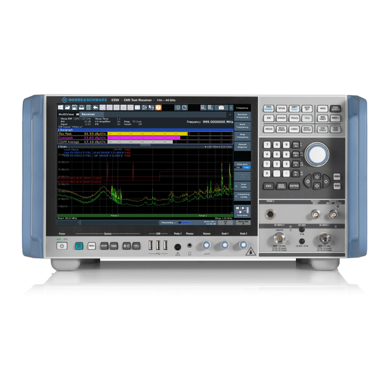
On the instrument tour, you can learn about the different control elements and connec- tors on the front and back panel of the R&S ESW. 5.1 The front panel The front panel contains the main control elements of the R&S ESW in addition to vari- ous connectors as shown in Figure 5-1. -
Page 40: Display (Touchscreen)
The front panel 5.1.1 Display (touchscreen) The touchscreen on the front panel of the R&S ESW displays the measurement results. Additionally, the screen display provides status and setting information and allows you to switch between various measurement tasks. The screen is touch-sensi- tive, offering an alternative means of user interaction for quick and easy handling of the instrument. -
Page 41: Power Key
® Instrument tour R&S The front panel To imitate a right-click by mouse using the touchscreen, for example to open a context- sensitive menu for a specific item, press the screen for about 1 second. 5.1.2 Power key The power key is on the lower left corner of the front panel. It starts up and shuts down the instrument. -
Page 42: Probe Power Connector (3 And 5 Pins)
The R&S ESW provides two RF inputs for connection of a device under test (DUT) to the R&S ESW. The DUT is connected to the RF Input via cable and an approriate con- nector (for example a male N connector). -
Page 43: Trigger Input And Output
® Instrument tour R&S The front panel For AC-coupling, a DC input voltage of 50 V must never be exceeded. For DC-cou- pling, DC voltage must not be applied at the input. In both cases, noncompliance will destroy the input mixers. The first RF Input supports a frequency range from 2 Hz to f and an attenuation range from 0 dB to 75 dB. - Page 44 ® Instrument tour R&S The front panel 5.1.10.1 Rotary knob The rotary knob has several functions: ● For numeric entries: increments (clockwise direction) or decrements (counter- clockwise direction) the instrument parameter at a defined step width ● In lists: toggles between entries ●...
-
Page 45: Keypad
® Instrument tour R&S The front panel The [Undo] function is not available after a [Preset] or "Recall" operation. When these functions are used, the history of previous actions is deleted. 5.1.11 Keypad The keypad is used to enter alphanumeric parameters, including the corresponding units (see also Chapter 6.4.2, "Entering alphanumeric parameters",... - Page 46 ® Instrument tour R&S The front panel Provides functionality to define frequency parameters, for example: ● the receiver or center frequency ● the frequency offset Provides functionality to configure the frequency span. Provides functionality to configure amplitude or level characteristics, for example: ●...
-
Page 47: The Rear Panel
5.2 The rear panel The rear panel contains various connectors as shown in Figure 5-2. Figure 5-2: Rear panel of the R&S ESW 1 = DisplayPort connector 2 = DVI connector 3 = LAN connector 4 = Removable hard drive... -
Page 48: Removable Hard Disk
27. 5.2.3 Display port and DVI You can connect an external monitor or other display device to the R&S ESW to pro- vide an enlarged display. Two different types of connectors are provided for this pur- pose: ●... -
Page 49: Lan Connector
30. 5.2.4 LAN connector The LAN interface allows you to connect the R&S ESW to a local network for remote control, printouts or data transfer. The assignment of the RJ-45 connector supports twisted-pair category 5 UTP/STP cables in a star configuration (UTP stands for unshielded twisted pair, and STP for shielded twisted pair). -
Page 50: Aux. Port
The external generator control option provides an additional GPIB and an "AUX con- trol" connector. The GPIB connector can be used to connect the external generator to the R&S ESW. The 9-pole SUB-D female "AUX control" connector is required for TTL synchronization, if supported by the generator. -
Page 51: Labels On R&S Esw
ID", on page 51 Table 5-2: Labels regarding R&S ESW and environment safety Labeling in line with EN 50419 for disposal of electrical and electronic equipment after the prod- uct has come to the end of its service life. For more information, see the product user manual, chapter "Disposal". - Page 52 ® Instrument tour R&S The rear panel The serial number is used to define the default instrument name, which is: <Type><variant>-<serial_number> For example, ESW26-123456. The instrument name is required to establish a connection to the instrument in a LAN. User Manual 1177.6298.02 ─ 13...
-
Page 53: Operating The Instrument
Understanding the display information 6 Operating the instrument The following topics provide an overview on how to work with the R&S ESW. They describe what kind of information is displayed in the diagram area, how to interact with the R&S ESW, and how to use the online help. -
Page 54: Channel Bar
59 6.1.1 Channel bar Using the R&S ESW you can handle several different measurement tasks (channels) at the same time (although they can only be performed asynchronously). For each channel, a separate tab is displayed on the screen. To switch from one channel display to another, simply select the corresponding tab. - Page 55 ® Operating the instrument R&S Understanding the display information Icons in the channel bar The star icon ( ) on the tab label indicates that the displayed trace no longer matches the current instrument settings. This can be the case, for example, if a trace is frozen and the instrument settings are changed.
-
Page 56: Window Title Bar
6.1.2 Window title bar Each channel in the R&S ESW display can contain several windows. Each window can display either a graph or a table as a result of the channel measurement. Which type of result evaluation is displayed in which window is defined in the display configuration (see Chapter 6.6, "Displaying... -
Page 57: Marker Information
® Operating the instrument R&S Understanding the display information Trace number Trace mode Trace color Detector Trace color Color of trace display in diagram Trace no. Number of the trace (1 to 6) Detector Abbreviation of the detector assigned to the trace: ●... -
Page 58: Frequency And Span Information In Diagram Footer
® Operating the instrument R&S Understanding the display information Marker information in marker table In addition to the marker information displayed within the diagram grid, a separate marker table can be displayed beneath the diagram. This table provides the following information for all active markers: Label Information... -
Page 59: Error Information
Operating the instrument R&S Understanding the display information Instrument status The R&S ESW is configured for operation with an external reference. Selecting the "Ext Ref" icon opens a dialog box to configure the external refer- ence. Progress The status of the current operation is displayed in the status bar. -
Page 60: Accessing Functions
MultiView tab always displays the information for the currently selected channel only. For a description of possible errors, see the R&S ESW user manual. 6.2 Accessing functions All tasks necessary to operate the instrument can be performed using the user inter- face. -
Page 61: Toolbar
You can hide the toolbar display, for example when using remote control, in order to enlarge the display area for the measurement results ("Setup > Display > Displayed Items"). See the R&S ESW User Manual for details. Windows: opens the Windows "Start" menu and task bar. -
Page 62: Softkeys
® Operating the instrument R&S Accessing functions Multiple zoom mode: multiple zoom areas can be defined for the same diagram. Zoom off: displays the diagram in its original size. SmartGrid: activates "SmartGrid" mode to configure the screen layout. Sequencer: opens the "Sequencer" menu to perform consecutive measurements. Help (+ Select): allows you to select an element for which context-specific help is dis- played. -
Page 63: Context Menus
® Operating the instrument R&S Accessing functions Recognizing the softkey status by color Color Meaning orange associated dialog box is open blue associated function is active; for toggle keys: currently active state gray instrument function is temporarily not available due to a specific setting or missing option You can hide the softkey display, e.g. -
Page 64: Changing The Focus
® Operating the instrument R&S Entering data The on-screen keyboard display can be switched on and off as desired using the "On- Screen Keyboard" function key beneath the screen. When you press this key, the display switches between the following options: ●... -
Page 65: Entering Numeric Parameters
® Operating the instrument R&S Entering data ● Using a connected external keyboard Transparent dialog boxes You can change the transparency of the dialog boxes to see the results in the windows behind the dialog box. Thus, you can see the effects that the changes you make to the settings have on the results immediately. - Page 66 ® Operating the instrument R&S Entering data You can change the default behavior of the keypad for text input. This is useful if you frequently enter numeric values in text fields, for example to define file names consist- ing of numbers. For details, see "Number block behavior"...
-
Page 67: Touchscreen Gestures
® Operating the instrument R&S Touchscreen gestures Key name Series of (special) characters and number provided (upper inscription) D E F 9 É G H I 4 J K L 5 M N O 6 Ň Ö P Q R S 1 T U V 2 Ü... - Page 68 ® Operating the instrument R&S Touchscreen gestures Dragging Move your finger from one position to another on the display, keeping your finger on the display the whole time. By dragging your finger over a table or diagram you can pan the displayed area of the table or diagram to show results that were previously out of view.
- Page 69 ® Operating the instrument R&S Touchscreen gestures Figure 6-4: Spreading Touch gestures in diagrams change measurement settings When you change the display using touch gestures, the corresponding measurement settings are adapted. This is different to selecting an area on the screen in zoom mode, where merely the resolution of the displayed trace points is changed temporarily (graphical zoom).
-
Page 70: Displaying Results
For each evaluation method the results are displayed in a separate window in the tab. The R&S ESW allows you to configure the display to suit your specific requirements and optimize analysis. 6.6.1 Activating and deactivating channels When you activate an application, a new measurement channel is created which deter- mines the measurement settings for that application. - Page 71 ® Operating the instrument R&S Displaying results To start a new channel 1. Select the [Mode] key. 2. In the "Mode" dialog box, select the required application on the "New Channel" tab. A new tab is displayed for the new channel. Remote command: on page 457/ INSTrument:CREate[:NEW]...
-
Page 72: Laying Out The Result Display With The Smartgrid
® Operating the instrument R&S Displaying results Select the "Close" icon on the tab of the measurement channel. The tab is closed, any running measurements are aborted, and all results for that channel are deleted. Remote command: on page 458 INSTrument:DELete 6.6.2 Laying out the result display with the smartgrid Measurement results can be evaluated in many different ways, for example graphically,... - Page 73 ® Operating the instrument R&S Displaying results 6.6.2.1 Background information: the smartgrid principle SmartGrid display During any positioning action, the underlying SmartGrid is displayed. Different colors and frames indicate the possible new positions. The position in the SmartGrid where you drop the window determines its position on the screen. Figure 6-5: Moving a window in SmartGrid mode The brown area indicates the possible "drop area"...
- Page 74 ® Operating the instrument R&S Displaying results Figure 6-6: SmartGrid window positions 1 = Insert row above or below the existing row 2 = Create a new column in the existing row 3 = Replace a window in the existing row SmartGrid functions Once the evaluation icon has been dropped, icons in each window provide delete and move functions.
- Page 75 ® Operating the instrument R&S Displaying results 6.6.2.3 How to add a new result window Each type of evaluation is displayed in a separate window. Up to 16 individual windows can be displayed per channel (i.e. per tab). 1. Activate SmartGrid mode. All evaluation methods available for the currently selected measurement are dis- played as icons in the evaluation bar.
-
Page 76: Changing The Size Of Windows
® Operating the instrument R&S Displaying results A blue area shows where the window will be placed. 3. Move the window until a suitable area is indicated in blue. 4. Drop the window in the target area. The windows are rearranged to the selected layout, and "Delete" and "Move" icons are displayed in each window. -
Page 77: Switching Between A Split And Maximized Window Display
Zooming into the diagram 6.7 Getting help If any questions or problems concerning the R&S ESW arise, an extensive online help system is provided on the instrument and can be consulted at any time. The help sys- tem is context-sensitive and provides information specifically for the current operation or setting to be performed. -
Page 78: Remote Control
A topic containing information about the selected (now focused) screen element is displayed. 6.8 Remote control In addition to working with the R&S ESW interactively, located directly at the instru- ment, it is also possible to operate and control it from a remote PC. Various methods for remote control are supported: ●... -
Page 79: Remote Desktop Connection
Windows, Microsoft offers the Remote Desktop Client as an add-on. 6.8.2 Connecting a PC via the GPIB interface You can connect a PC to the R&S ESW via the GPIB interface to send remote com- mands to control and operate the instrument. You can configure the GPIB address and the ID response string. -
Page 80: Applications
The R&S ESW provides several applications for different analysis tasks (for example the Receiver application or the I/Q Analyzer). When you activate an application, the R&S ESW creates a new measurement channel which in turn determines the mea- surement settings for that application. You can use the same application with different measurement settings by creating several channels for the same application. -
Page 81: Available Applications
555 DISPlay:FORMat 7.2 Available Applications The R&S ESW provides several applications for specific measurement tasks. Spectrogram application Spectrogram measurements are not a separate application, but rather a trace evalua- tion method, thus they are available as an evaluation method for the Display Configu- ration, not by creating a new channel. - Page 82 INSTrument[:SELect] Real-Time Spectrum The Real-Time Spectrum application requires an instrument equipped with the Real- Time Spectrum option. This application provides real-time measurement functions. For details see the R&S ESW Real-Time User Manual. Remote command: INST:SEL RTIM, see on page 459 INSTrument[:SELect] User Manual 1177.6298.02 ─...
-
Page 83: Starting An Application
Starting an Application 7.3 Starting an Application Access ► [MODE] > "<application>" The default application that is running when you start the R&S ESW is the Receiver application. The remote commands required to perform these tasks are described in Chapter 14.4, "Application... -
Page 84: Running A Sequence Of Measurements
® Applications R&S Running a sequence of measurements You can also define a fix set of parameters that are synchronized between applica- tions. For more information see Chapter 12.8, "Synchronizing measurement channel configuration", on page 387. To deactivate a channel, simply close the corresponding tab. Channel.........................84 Replace Current Channel....................84... - Page 85 ® Applications R&S Running a sequence of measurements channel. However, in order to perform the configured measurements consecutively, a Sequencer function is provided, which changes the channel of the instrument as required. If activated, the measurements configured in the currently defined "Channel"s are performed one after the other in the order of the tabs.
- Page 86 ® Applications R&S Running a sequence of measurements Example: Sequencer procedure Assume the following active channel definition: Tab name Application Sweep mode Sweep count Spectrum Spectrum Cont. Sweep Spectrum 2 Spectrum Single Sweep Spectrum 3 Spectrum Cont. Sweep IQ Analyzer IQ Analyzer Single Sweep For Single Sequence, the following sweeps will be performed:...
-
Page 87: Sequencer Settings
® Applications R&S Running a sequence of measurements The "Single Sweep" and "Continuous Sweep" softkeys control the sweep mode for the currently selected channel only; the sweep mode only has an effect the next time the Sequencer activates that channel, and only for a channel-defined sequence. In this case, a channel in single sweep mode is swept only once by the Sequencer. - Page 88 ® Applications R&S Running a sequence of measurements 2. In the toolbar, select the "Sequencer" icon. The "Sequencer" menu is displayed. 3. Toggle the "Sequencer" softkey to "On". A continuous sequence is started immediately. 4. To change the Sequencer mode and start a new sequence immediately, select the corresponding mode softkey, or press the [Run Single] or [Run Cont] key.
-
Page 89: Measurements And Result Displays
The R&S ESW allows you to select the measurement mode for the bargraph and the scan separately. When you select a continuous bargraph measurement, IF analysis (including the spectrogram) is also performed continuously. - Page 90 Count. In that case, the measurement stops when all measure- ments defined by the scan count or bargraph count are done. The R&S ESW allows you to select the measurement mode for the bargraph and the scan separately. When you select a single bargraph measurement, IF analysis also stops when the bargraph measurement stops.
-
Page 91: Bargraph Configuration
® Measurements and result displays R&S Bargraph configuration For more information regarding the general functionality of the sequencer, see Chap- ter 7.4, "Running a sequence of measurements", on page 84. In the receiver application, you can select whether to: ● Run a bargraph measurement each time the receiver application has its turn. - Page 92 When auto ranging has been turned on, the range is adjusted to the sig- nal level. The R&S ESW supports the simultaneous use of up to four different detectors in the bargraph result display. If you select an additional detector, the R&S ESW adds the corresponding number of bargraphs to the result display.
- Page 93 Bargraph configuration When you are performing a scan that is not based on a scan table, the R&S ESW applies the bargraph settings (detector, measurement time etc.) to the scan. The remote commands required to configure the bargraph are described in Chap- ter 14.5.4, "Bargraph...
- Page 94 "Max Hold Reset" on and off, regardless of the receiver settings. When you turn on the max hold information, the R&S ESW shows the highest level that has been measured for each active bargraph (detector), including the frequency where it was measured.
- Page 95 (Current parameters), the bandwidth of the bargraph. The R&S ESW supports a selected set of resolution bandwidths. If you enter a number that is not supported, the R&S ESW rounds the value up to next available bandwidth. More information...
-
Page 96: Test Automation
The receiver application supports the following types of resolution filter. ● Filters with a 3 dB bandwidth The R&S ESW provides bandwidths with a stepsize of 1-2-3-5-10-..For details, refer to the data sheet. ● Filters with a 6 dB bandwidth... -
Page 97: Calculating The Number Of Measurement Points
The number of measurement points (or sweep points in some applications) determines the amount of data that is captured in one measurement. At each measurement point, the R&S ESW collects one set of data, which contains, for example, the signal level at a given frequency. - Page 98 In the receiver application, the number of measurement points considered in a scan is determined by the frequency range and the selected frequency step size: the R&S ESW runs a measurement every x Hz, so the actual number of measurement points depends on frequency range you are scanning. The maximum number of mea- surement points that a scan supports is 10,000,001 (this is only possible with two or less active traces).
-
Page 99: Line Impedance Stabilization Network (Lisn) Control
If the sweep count is 0 or 1, the R&S ESW runs a single measurement from start to stop frequency. If the sweep count is greater than 1, the R&S ESW repeats the measurement from start to stop frequency a corresponding number of times. - Page 100 Connecting a LISN A LISN is connected to the R&S ESW via its user port. To connect the LISN to the R&S ESW, a control line and an adapter are required. The control line (or cable) controls which phase of the LISN is to be tested and outputs the information to the user port.
-
Page 101: Overview Of Receiver Measurements
You can also use a direct connection without a filter, e.g. when you use the R&S ESW in a shielded room. In that case, you can use the following cables. - Page 102 Peak search The Peak Search function of the R&S ESW can be used to create a peak list contain- ing only the measurement values of high interferers. In a fast prescan the signal is measured against a limit line, and the level values above the set margin are written into the peak list.
- Page 103 ® Measurements and result displays R&S Test automation Data Reduction using the Peak List EMI measurements may take some time because the time constants of up to 160 ms prescribed by the standard for the quasipeak weighting lead to long measurement times per each value.
- Page 104 It is then still possible to perform the measurement in a reasonable time frame. During the final measurement, the R&S ESW performs a measurement on each fre- quency in the peak list. When done, it updates the preliminary results in the peak list with those found during the final measurement.
- Page 105 Control of the final measurement is possible in interactive final measurement mode. In interactive final measurement mode, the R&S ESW stops on each frequency of the peak list. If required, the frequency can be fine tuned, e.g. if the interferer has shifted.
-
Page 106: Selecting A Test Sequence
® Measurements and result displays R&S Test automation IF Analysis always applies resolution filters with a 6 dB bandwidth, while filters with a 3 dB bandwidth are not supported. 8.3.2 Selecting a test sequence Access: "Overview" > "Test Automation" > "Overview" The first tab of the "Test Automation"... - Page 107 Starting a complete automated test sequence ► Press the [RUN SINGLE] key. The R&S ESW starts the test sequence. It stops the test sequence at the point you have defined (either after the scan, the peak search or the final measurement).
- Page 108 You can select the time domain scan mode with the "TDS Optimization" feature. ● Fast The R&S ESW uses a large analysis bandwidth (FFT size) for the data capture in favor of an increased measurement speed, regardless of the detector you are using.
-
Page 109: Performing A Scan
® Measurements and result displays R&S Test automation The R&S ESW always applies a small analysis bandwidth in favor of a high dynamic range, regardless of the detector you are using. Remote command: on page 475 [SENSe:]FREQuency:TDOPtim 8.3.3 Performing a scan ●... - Page 110 Access: [RUN SGL] / [RUN CONT] > "Hold Scan" The R&S ESW allows you to hold a scan any time with the "Hold Scan" feature. If you hold it, the scan is interrupted immediately. When held, you can change settings that have a direct effect on the scan, for example the frequency.
- Page 111 When you change the measurement channel while a scan is running (for example switch to a spectrum channel), the R&S ESW holds the scan. When you change back to the receiver channel in which the scan is running, you can resume the scan from the hold frequency.
- Page 112 The start and stop frequencies ("Scan Start" and "Scan Stop") define the global fre- quency range considered during a scan. The minimum and maximum frequencies supported by the R&S ESW depend on the instrument model and are defined in the datasheet.
- Page 113 ® Measurements and result displays R&S Test automation On the other hand, when the global frequency range is larger than the scan ranges, adjusting the frequency contracts the global frequency range. This feature is useful when the global frequency range is smaller than the scan ranges, because frequencies outside the global range are not considered in a scan based on a scan table.
- Page 114 ® Measurements and result displays R&S Test automation For each scan range, you can customize the following parameters. ● "Range Start and Range Stop" on page 114 ● "Step Size" on page 114 ● "Measurement Bandwidth" on page 95 ● "Measurement Time"...
- Page 115 (Current parameters), the bandwidth of the bargraph. The R&S ESW supports a selected set of resolution bandwidths. If you enter a number that is not supported, the R&S ESW rounds the value up to next available bandwidth. More information...
- Page 116 The auto ranging feature in the receiver remains active even if you change the attenua- tion and preamplifier properties in other measurement channels and then return to the receiver application. The R&S ESW also allows you to determine the best attenuation automatically. ● In the receiver application, turn on the "Auto Ranging" feature.
- Page 117 In addition to the standard preamplifier, a low noise amplifier is available as an optional hardware component. You can configure the preamplifier manually (➙ "Value" menu) or, if you are using the Auto Range functionality, let the R&S ESW pick the ideal configuration (➙ "Auto" menu). ● "Auto Off"...
-
Page 118: Performing A Peak Search
Defining peak characteristics (or "When is a peak a peak?") If a signal is, for example, very flat, contains a lot of noise or does not contain many peaks, the R&S ESW might miss potential peaks or detect peaks that really are no peaks. - Page 119 The automatic peak search that is part of automated tests is an easy way to find peaks: the R&S ESW searches for peaks after the scan is done based on the condi- tions you have defined for the peak search (peak excursion and limit margin). It then writes the peaks into the peak list.
- Page 120 ● "Peaks" When you have selected the "Peaks" search mode, define the number of peaks the R&S ESW looks for during a peak search. The range is from 1 to 500 peaks. ● "Subranges" User Manual 1177.6298.02 ─ 13...
- Page 121 Selects one or more limit lines to evaluate for a peak search. The table shows all limit lines available on the R&S ESW that are compatible to the current measurement configuration. You can activate the limit line by marking the cor- responding checkbox and assigning the limit line to a trace.
- Page 122 The peak list contains the frequencies on which the peak search has identified peaks. It can be used as the basis of the final measurement. Modifying a peak list (alternate way) The R&S ESW also provides an alternate way to modify a peak list. More information.
- Page 123 Displaying peaks as symbols..................124 Editing a peak list The R&S ESW allows you to edit a peak list that has been created, or even create a peak list that is not based on an automatic peak search. ● Adding a new frequency To add a new peak to the peak list, enter a frequency in the corresponding field and add it to the list with the "Insert"...
- Page 124 Test automation Sorting the peak list By default, the R&S ESW sorts the peaks by their "Frequency" in ascending order. Alternatively, you can sort the peak list by the distance of a peak to the limit line (➙ "Delta Limit"). This is also done in ascending order.
-
Page 125: Performing Final Measurements
Automatic vs interactive final measurements The R&S ESW provides two methods to run a final measurement: an automatic final measurement and an interactive one. An automatic final measurement measures all frequencies in the peak list automatically with limited means of interaction. - Page 126 If you select the interactive final measurement, the R&S ESW initiates the following sequence. 1. The R&S ESW tunes to the first frequency in the peak list. The measurement con- figuration is as defined previously. 2. The R&S ESW positions a marker on that frequency and interrupts the measure- ment.
- Page 127 ® Measurements and result displays R&S Test automation Note that it is possible to start with an automatic measurement and later change into interactive mode. Likewise, it is possible to start measuring in interactive mode and later change into automatic mode. ●...
- Page 128 ® Measurements and result displays R&S Test automation Trace Mode Defines the update mode for subsequent traces. For more information, see Chapter 10.3.1.2, "Analyzing several traces - trace mode", on page 227. "Clear Write" Displays the level that has been measured last at each trace point. The old trace is overwritten.
- Page 129 Working with the final measurement results Access: "Overview" > "Test Automation" > "Final Result" When the final measurement is done, the R&S ESW writes the results into a table that looks and feels similar to the peak list. Editing entries is, however, not possible.
- Page 130 ® Measurements and result displays R&S Test automation Figure 8-15: Overview of the "Final Results" table The functionality and information provided by the final results dialog box is similar to that provided by the peak list. Functions to manage final results described elsewhere: ●...
-
Page 131: Configuring Line Impedance Stabilization Networks (Lisn)
Allows you to add a comment to each result as required. 8.3.6 Configuring line impedance stabilization networks (LISN) Access: "Overview" > "Test Automation" > "LISN" The R&S ESW supports several LISN models and provides functionality to control these devices. For more information about using a LISN, see Chapter 8.3.1.3, "Line impedance stabili-... - Page 132 500. LISN Type........................132 Phase.......................... 132 High-Pass Filter 150 kHz.................... 133 LISN Type Selects the LISN used for the measurement. The following LISNs are supported by the R&S ESW: ● R&S ENV216 ● R&S ENV432 ● R&S ENV4200 ●...
- Page 133 "Scan" or the "Final Test" column ("On" considers the phase in the measurement, "Off" ignores the phase in the measurement). If you are measuring more than one phase, the R&S ESW performs a measure- ment for each of the selected phases.
-
Page 134: Cispr Apd Measurements
It allows you to measure unsteady levels. APD vs CISPR APD Note that the R&S ESW also provides an APD measurement for general purposes in the spectrum application. This general APD function does not comply with CISPR 16-1-1 in various aspects and cannot be used for CISPR APD measurements. - Page 135 ® Measurements and result displays R&S CISPR APD Measurements Refer to the documentation of the spectrum application for a detailed description of these parameters (including remote commands). ● Amplitude settings: are similar to those in the spectrum application. Refer to the documentation of the spectrum application for a detailed description of these parameters (including remote commands).
- Page 136 ® Measurements and result displays R&S CISPR APD Measurements Refer to the documentation of the spectrum application for a detailed description of these parameters (including remote commands). ● Output settings: are similar to those available in the receiver application. – Chapter 9.6.5, "Configuring outputs (IF / video / demodulation)", on page 184...
-
Page 137: Common Measurement Settings
206 9.1 Using the fast access knobs The R&S ESW features two small knobs on its front panel labeled "Knob 1" and "Knob 2". These knobs are designed to provide fast access to a (predefined) set of settings that you are using regularly, and change these settings without using the user interface. - Page 138 Note: The parameter stepsize of the knobs is the same as if you were using the rotary knob. When you are using the R&S ESW for the first time, each knob carries a predefined function. These predefined functions differ, depending on the application you are using.
- Page 139 "Vertical Line" and thus refer to display lines. 4. Save the configuration to a file and restore it later on. "File Explorer": Instead of using the file manager of the R&S ESW firmware, you can also use the Microsoft Windows File Explorer to manage files.
-
Page 140: Using The Fast Access Panel
® Common measurement settings R&S Using the fast access panel 9.2 Using the fast access panel Access: > "Fast Access" The "Fast Access" panel is designed to provide fast access to a (predefined) set of set- tings that you are using regularly, and change these settings without accessing dialog boxes or softkey menus. - Page 141 1. Tap one of the interfaces to configure knobs in the user interface. The R&S ESW opens a dialog box with several tabs. One tab each to configure the fast access knobs, one to configure the fast access display, and tabs to configure multimedia controllers.
-
Page 142: Using The User Port Panel
The "User Port" panel is designed to configure the optional user port (AUX port) on the rear of the R&S ESW. Using the user port, you can transmit bit patterns in two direc- tions, depending on the actual selected signal direction. -
Page 143: The Notes Display
® Common measurement settings R&S The Notes Display For more information about the pin assignment of the user port, see Chapter 5.2.9, "Aux. port", on page 50. For more information about the pin to bit assignment, refer to the description of the remote command . -
Page 144: Configuration Overview
® Common measurement settings R&S Configuration overview Clear notes display: DISPlay[:WINDow<n>][:SUBWindow<w>]:NOTes:CLEar on page 647 9.5 Configuration overview Throughout the measurement channel configuration, an overview of the most important currently defined settings is provided in the configuration "Overview". The configuration overview is displayed when you select the "Overview" softkey, which is available at the bottom of all softkey menus. -
Page 145: Data Input And Output
(for example the "Peak List"). 9.6 Data input and output The R&S ESW can analyze signals from different input sources and provide various types of output (such as video or trigger signals). Functions to control in- and outputs described elsewhere: ●... -
Page 146: Configuring The Input
Pulse Limiter....................... 147 Input Coupling The RF input of the R&S ESW can be coupled by alternating current (AC) or direct cur- rent (DC). Note that the "Input Coupling" feature is only available for input 2 when the pulse lim- iter is turned off. -
Page 147: Configuring The Preselector
For some measurements, the reference impedance for the measured levels of the R&S ESW can be set to 50 Ω or 75 Ω. Select 75 Ω if the 50 Ω input impedance is transformed to a higher impedance using a 75 Ω... - Page 148 ® Common measurement settings R&S Data input and output Note that the signal path through the YIG preselector is always orange. This is because the YIG preselector is always used for measurements on frequencies greater then 8 GHz. A bypass of the YIG preselector is not possible. (For measurements up to 8 GHz, you can use the optional preselector, see "Preselec- tor Filter Settings"...
-
Page 149: Optional External Mixers
If the R&S ESW External Mixer option is installed, an external mixer can be connected to the R&S ESW to increase the available frequency range. In this case, the input to measure is not taken from the RF input connector, but from the [Ext Mixer] connec- tor(s). - Page 150 ® Common measurement settings R&S Data input and output 9.6.3.1 Basics on external mixers Some background knowledge on basic terms and principles used with external mixers is provided here for a better understanding of the required configuration settings. ● Frequency ranges....................
- Page 151 DC voltage can be set via the "BIAS" function using the D/A converter of the R&S ESW. The value to be entered is not the voltage but the short-circuit current. The current is defined in the "Bias Settings" or set to the value of the conversion loss table.
- Page 152 To select a conversion loss table for use in a measurement, you merely have to select the serial number for the external mixer in use. The R&S ESW automatically selects the correct cvl file for the current IF. As an alternative, you can also select a user- defined conversion loss table (.acl file).
- Page 153 Common measurement settings R&S Data input and output Before copying any files to the C:\R_S\Instr\User\cvl\ directory, the R&S ESW firmware moves any existing user-defined cvl tables to a backup subdirectory. To use a user-defined cvl table later, select the file in the C:\R_S\Instr\User\cvl\backup directory.
- Page 154 ® Common measurement settings R&S Data input and output Figure 9-3: Signal identification function (Signal ID) with optional external mixer The reference sweep is performed using an LO setting shifted downwards by 2*IF/ <Harmonic order>. Input signals in the desired sideband that are converted using the specified harmonic are displayed in both traces at the same position on the frequency axis.
- Page 155 This is due to the fact that the LO output power of the R&S ESW varies with the frequency, and also due to the non-ideal characteristics of the mixer. A certain tolerance should therefore be permitted for the comparison of the signal levels in the test sweep and reference sweep.
- Page 156 ® Common measurement settings R&S Data input and output Examining unwanted mixer products with small span With large spans in which non-modulated sine-wave signals are represented as single lines, unwanted mixer products are generally completely blanked out. However, if you examine the frequency range containing a blanked signal in detail using a small span, e.g.
- Page 157 The external mixer is set to use the 2nd order harmonic. The signal recorded in the test sweep is displayed by trace 1. The IF filter of the R&S ESW is represented at a 3 dB bandwidth of 20 kHz, the real IF bandwidth being 30 kHz. If, however, the 3 dB band- width of the signal recorded in the reference sweep is examined (trace 2), it will be found to be larger exactly by a factor of 2.
- Page 158 ® Common measurement settings R&S Data input and output Figure 9-5: Unwanted mixer products displayed for small span 9.6.3.2 External mixer settings Access: [INPUT/OUTPUT] > "External Mixer Config" ● Mixer settings......................158 ● Basic settings......................162 ● Managing conversion loss tables................
- Page 159 ® Common measurement settings R&S Data input and output External Mixer (State)....................159 RF Start / RF Stop.......................159 Handover Freq......................160 Band..........................160 Overrange......................160 Preset Band........................ 160 Mixer Type........................160 Mixer Settings (Harmonics Configuration)..............161 └ Range 1/Range 2..................161 └ Harmonic Type....................161 └...
- Page 160 ® Common measurement settings R&S Data input and output Handover Freq If due to the LO frequency the conversion of the input signal is not possible using one harmonic, the band must be split. An adjacent, partially overlapping frequency range can be defined using different harmonics.
- Page 161 Defines the conversion loss via the table selected from the list. Pre- defined conversion loss tables are often provided with the external mixer and can be imported to the R&S ESW. Alternatively, you can define your own conversion loss tables. Imported tables are checked for compatibility with the current settings before being assigned.
- Page 162 ® Common measurement settings R&S Data input and output on page 516 [SENSe:]MIXer<x>:LOSS:TABLe[:LOW] Average for range 2: on page 515 [SENSe:]MIXer<x>:LOSS:HIGH Table for range 2: on page 516 [SENSe:]MIXer<x>:LOSS:TABLe:HIGH Basic settings Access: [INPUT/OUTPUT] > "External Mixer Config" > "Basic Settings" The basic settings concern general use of an external mixer.
- Page 163 ® Common measurement settings R&S Data input and output To store the bias setting in the currently selected conversion loss table, select the Write to CVL table button. Remote command: on page 511 [SENSe:]MIXer<x>:BIAS[:LOW] on page 510 [SENSe:]MIXer<x>:BIAS:HIGH Write to CVL table ← Bias Value Stores the bias setting in the currently selected "Conversion Loss Table"...
- Page 164 "Conversion Loss" on page 161). Note: Before copying any files to the C:\R_S\Instr\User\cvl\ directory, the R&S ESW firmware moves any existing user-defined cvl tables to a backup subdirectory. To use a user-defined cvl table later, select the file in the C:\R_S\Instr\User\cvl\backup directory.
-
Page 165: File Name
® Common measurement settings R&S Data input and output Shift x.......................... 166 Shift y.......................... 167 Save..........................167 File Name Defines the name under which the table is stored in the C:\R_S\Instr\User\cvl\ directory on the instrument. The name of the table is identical with the name of the file (without extension) in which the table is stored. -
Page 166: Mixer S/N
® Common measurement settings R&S Data input and output Remote command: on page 520 [SENSe:]CORRection:CVL:MIXer Mixer S/N Specifies the serial number of the external mixer to which the table applies. The specified number is checked against the currently connected mixer number before the table can be assigned to the range. - Page 167 ® Common measurement settings R&S Data input and output Shift y Shifts all conversion loss values by a specific value. The value can be entered in the edit dialog box. The conversion loss function in the preview pane is shifted along the y- axis.
- Page 168 R&S ESW, cover the two front connectors [LO OUT / IF IN] and [IF IN] with the SMA caps supplied. 1. Connect the LO OUT / IF IN output of the R&S ESW to the LO port of the external mixer.
- Page 169 ® Common measurement settings R&S Data input and output ters. If the selected table is not valid for the selected band, an error message is dis- played. If no conversion loss table is available yet, create a new table first (as described in "To define a new conversion loss table"...
- Page 170 INPUT Figure 9-6: External Mixer test setup 1. Connect the [LO OUT / IF IN] output of the R&S ESW to the [LO/IF] port of the external mixer. 2. Connect the multiplier to the RF input of the external mixer.
-
Page 171: External Generator
® Common measurement settings R&S Data input and output To activate and configure the external mixer 1. Select "INPUT > Input Source Config > External Mixer: ON" to activate the external mixer for the current application. 2. Select "Mixer Settings > Band" to define the required frequency range. 3. - Page 172 External Generator Control option. Using the TTL interface allows for considerably higher measurement rates than pure GPIB control, because the frequency stepping of the R&S ESW is directly coupled with the frequency stepping of the generator. For details see "Coupling the frequencies"...
- Page 173 This measurement yields the transmission characteristics of a two-port network. The external generator is used as a signal source. It is connected to the input connector of the DUT. The input of the R&S ESW is fed from the output of the DUT. A calibration User Manual 1177.6298.02 ─ 13...
- Page 174 R&S ESW and that you enable usage of the external reference on the R&S ESW via "SETUP" > "Reference" > "External Refer- ence".
- Page 175 ® Common measurement settings R&S Data input and output Overview of supported generators Generator Model Driver file TTL sup- Generator type Model Driver file TTL sup- type port port SGS100A 6 GHz SGS100A6 3 GHz SMJ03 12 GHz SGS100A12 6 GHz SMJ06 SGT100A 3 GHz...
- Page 176 ® Common measurement settings R&S Data input and output Generator Model Driver file TTL sup- Generator type Model Driver file TTL sup- type port port SMC100A 1 GHz SMC100A1 4 GHz SMU04 3 GHz SMC100A3 4 GHz SMU04B31 SMCV100B 3 GHz SMCV100B3 6 GHz SMU06...
- Page 177 Automatic coupling: a series of frequencies is defined (one for each sweep point), based on the current frequency at the RF input of the R&S ESW; the RF fre- quency range covers the currently defined span of the R&S ESW (unless limited by...
- Page 178 GPIB, and only when the setting procedure is finished, the R&S ESW can measure the next sweep point. For generators with a TTL interface, the R&S ESW sends a list of the frequencies to be set to the generator before the beginning of the first sweep. Then the R&S ESW starts the sweep and the next frequency point is selected by both the R&S ESW and the gen-...
- Page 179 ® Common measurement settings R&S Data input and output Example: Example for reverse sweep via minimum frequency = 100 MHz AnalyzerStart = 200 MHz AnalyzerStop = -150 MHz Offset = 20 MHz Numerator = Denominator = 1 →F = 50 MHz GeneratorStart →F = 50 MHz via F...
- Page 180 At a reference level of -10 dBm and at an external generator output level of the same value, the R&S ESW operates without overrange reserve. That means the R&S ESW is in danger of being overloaded if a signal is applied whose amplitude is higher than the reference line.
- Page 181 If available for the specified generator type, this option activates TTL synchronization via handshake. Using the TTL interface allows for considerably higher measurement rates, because the frequency stepping of the R&S ESW is directly coupled with the frequency stepping of the generator. For more information on TTL synchronization, see "TTL synchronization"...
- Page 182 ® Common measurement settings R&S Data input and output Reference Selects the internal R&S ESW or an external frequency reference to synchronize the R&S ESW with the generator (default: internal). Remote command: on page 527 SOURce<si>:EXTernal<gen>:ROSCillator[:SOURce] Edit Generator Setup File...
- Page 183 "(Automatic) Source Frequency (Numerator/Denomi- nator/Offset)" on page 184). The RF frequency range covers the cur- rently defined span of the R&S ESW (unless limited by the range of the signal generator). "Manual" The generator uses a single fixed frequency, defined by...
-
Page 184: Configuring Outputs (If / Video / Demodulation)
With automatic frequency coupling, a series of frequencies is defined (one for each sweep point), based on the current frequency at the RF input of the R&S ESW. However, the frequency used by the generator may differ from the input from the R&S ESW. -
Page 185: Output Coupling
® Common measurement settings R&S Data input and output The remote commands required to configure the outputs are described in Chap- ter 14.6.2.1, "IF / video / demodulation", on page 532. Further information For more information about LISN control refer to Chapter 8.3.1.3, "Line impedance sta- bilization network (LISN) control",... -
Page 186: Selecting The Output Type
® Common measurement settings R&S Data input and output Selecting the output type Selects the type of analog signal you want to output. "IF Output" Outputs the IF signal (see "Configuring the output of the IF signal" on page 186 for available settings). (Unavailable for audio output.) "Video"... -
Page 187: Coupling
® Common measurement settings R&S Data input and output Remote command: on page 533 OUTPut<ou>:IF:IFFRequency Coupling ← Controlling and configuring the output Selects the type of current that is transferred at the output. Available for linear signal output. "AC Coupling" Rejects the DC component of the signal. -
Page 188: Configuring Lisns
Chapter 8.3.6, "Configuring line impedance stabilization net- works (LISN)", on page 131. 9.6.7 Configuring additional outputs Access: "Overview" > "Output" > "Additional Outputs" The R&S ESW provides additional outputs that you can use for various tasks. User Manual 1177.6298.02 ─ 13... - Page 189 Defines the usage of the variable "Trigger 3 Input/Output" connector on the rear panel "Input" The signal at the connector is used as an external trigger source by the R&S ESW. Trigger input parameters are available in the "Trigger" dialog box. User Manual 1177.6298.02 ─ 13...
- Page 190 (Default) Sends a trigger when the R&S ESW triggers. gered" "Trigger Sends a (high level) trigger when the R&S ESW is in "Ready for trig- Armed" ger" state. This state is indicated by a status bit in the STATus:OPERation reg- ister (bit 5), as well as by a low-level signal at the "AUX"...
-
Page 191: Amplitude And Vertical Axis Configuration
The input mixer of the R&S ESW is equipped with an overload protection mechanism. If you apply a signal whose power exceeds the specified limit (see datasheet), the con- nection between the RF input and the input mixer is cut off. The R&S ESW displays a corresponding message in the status display. - Page 192 For further protection of the input mixer, the R&S ESW does not allow you to select attenuation levels of less than 10 dB unless you explicitly turn on this feature ("10 dB...
- Page 193 Using the preamplifier The second tool that allows you to control measurement sensitivity is the preamplifier. In addition to the standard preamplifier available in every R&S ESW, an additional low noise amplifier is available as an optional component (R&S ESW-B24).
-
Page 194: Amplitude Settings
(150 kHz to 30 MHz). Or, you can split the preselection into two stages, each of which applies a separate filter: one from 150 kHz to 2 MHz, and another from 2 MHz to 30 MHz. In addition, the R&S ESW provides several notch filters to suppress certain frequency ranges completely. Using the "preselector"... - Page 195 ® Common measurement settings R&S Amplitude and vertical axis configuration Functions in the "Amplitude" dialog box described elsewhere: ● "Attenuation" on page 116 ● "Auto Range" on page 115 ● "Preamplifier" on page 117 ● "Input Selection" on page 117 ●...
-
Page 196: Diagram Scale
® Common measurement settings R&S Amplitude and vertical axis configuration Unit Selects the unit displayed on the vertical axis. The unit on the vertical axis represents the unit the results are evaluated in. You can select one of the following units: dBm, dBµV, dBpW, dBµA, dBmV, dBpT. Remote command: on page 544 CALCulate<n>:UNIT:POWer... -
Page 197: Preselector
® Common measurement settings R&S Frequency and span configuration Grid Range / Minimum Level..................197 Grid Range / Minimum Level Defines the scale of the vertical diagram axis. The display ranges go from 10 dB to 200 dB in 10 dB steps. Invalid entries or combi- nations of range and minimum level are rounded off to the nearest valid value. - Page 198 This concept is used by the IF analysis. In any way, make sure that the receiver frequency is at least twice as large as the reso- lution bandwidth. If you use a frequency that is lower, the R&S ESW automatically reduces the measurement bandwidth.
- Page 199 ® Common measurement settings R&S Frequency and span configuration 1 Hz 1 GHz 1 MHz Figure 9-14: Logarithmic x-axis scaling: the distance between measurement points is variable In the spectrum from 10 Hz to 100 Hz, the distance is a few Hz. Between 100 MHz and 1 GHz, the distance is several MHz.
-
Page 200: Frequency And Span Settings
® Common measurement settings R&S Frequency and span configuration Signal Tracking Access: "Overview" > "Frequency" > "Signal Tracking" tab Defines the settings for signal tracking. These settings are only available for spans > 0. If activated, after each sweep, the center frequency is set to the maximum level of the specified "Signal Track Trace"... - Page 201 Defines the receiver frequency. For a scan, make sure to define a frequency that is at least twice as large as the reso- lution bandwidth. If you use a frequency that is lower, the R&S ESW automatically reduces the bandwidth.
- Page 202 The R&S ESW always synchronizes to the position of the currently selected marker, even if it is a relative delta marker. The "Marker Tracking" and "Tune to Marker" softkeys are available in the "Marker To"...
- Page 203 The stepsize is coupled to the receiver frequency. ● When you change the frequency with the rotary knob, the R&S ESW increases or decreases the 4th digit of the receiver fre- quency. ● When you change the frequency with the arrow keys, the R&S ESW increases or decreases the 2nd digit of the receiver...
-
Page 204: Bandwidth And Filter Configuration
IF Signal Tracking Defines the characteristics for signal tracking. When you turn on signal tracking, the R&S ESW tracks the signal and updates the receiver frequency accordingly. The signal is assumed to be at highest level that has been found within the tracking bandwidth. The tracking bandwidth defines a search are around the receiver frequency. -
Page 205: Impact Of Bandwidth And Filter Settings
® Common measurement settings R&S Bandwidth and Filter Configuration 9.9.1 Impact of Bandwidth and Filter Settings For more background information about bandwidths and filters refer to the following topics: ● Chapter 8.3.1.1, "Selecting the measurement bandwidth", on page 96 9.9.2 Bandwidth and Filter Settings Access: "Overview"... -
Page 206: Trigger Configuration
An offset can be defined to delay the measurement after the trigger event, or to include data before the actual trigger event in time domain measurements (pre-trigger offset). Pre-trigger offsets are possible because the R&S ESW captures data continuously in the time domain, even before the trigger occurs. - Page 207 ® Common measurement settings R&S Trigger configuration Figure 9-15: Effects of Gate mode, Gate delay and Gate length User Manual 1177.6298.02 ─ 13...
- Page 208 ® Common measurement settings R&S Trigger configuration Example: By using a gate in sweep mode and stopping the measurement while the gate signal is inactive, the spectrum for pulsed RF carriers can be displayed without the superposi- tion of frequency components generated during switching. Similarly, the spectrum can also be analyzed for an inactive carrier.
-
Page 209: Triggering Measurements
Each measurement point is measured for a certain period of time (defined by the measurement time). If the gate closes before the R&S ESW is done with any par- ticular measurement point, the remaining time is measured when the gate opens again. -
Page 210: Trigger Source
Note: The "External Trigger 1" softkey automatically selects the trigger signal from the "TRIGGER 1 INPUT" connector on the front panel. For details, see the "Instrument Tour" chapter in the R&S ESW Getting Started manual. "External Trigger 1" Trigger signal from the "TRIGGER 1 INPUT" connector. -
Page 211: Trigger Offset
® Common measurement settings R&S Trigger configuration Trigger Offset Defines the time offset between the trigger event and the start of the sweep. For more information, see Chapter 9.10.1.1, "Trigger offset", on page 206. "values > 0" Measurement starts after the trigger event has occurred. "values <... -
Page 212: Gate Length
® Common measurement settings R&S Trigger configuration Remote command: on page 550 [SENSe:]SWEep:EGATe:HOLDoff Gate Length Defines how long the gate is open when it is triggered. The gate length can only be set in the edge-triggered gate mode. In the level-triggered mode the gate length depends on the level of the gate signal. -
Page 213: Common Analysis And Display Functions
® Common analysis and display functions R&S Result display configuration 10 Common analysis and display functions General methods and basic settings to display and analyze measurements, regardless of the operating mode, are described here. If you are performing a specific measure- ment task, using an application other than the Receiver application, be sure to check the specific application or mode description for settings and functions that may deviate from these common settings. -
Page 214: Laying Out The Result Display With The Smartgrid
® Common analysis and display functions R&S Result display configuration ● IF analysis – "IF analysis" on page 105 – "IF Analysis" on page 203 ● Spectrogram (for scan and IF analysis) – Chapter 10.3.1.3, "Working with spectrograms", on page 228 –... - Page 215 ® Common analysis and display functions R&S Result display configuration ● New windows are added by dragging an evaluation icon from the evaluation bar to the screen. The position of each new window depends on where you drop the eval- uation icon in relation to the existing windows.
- Page 216 ® Common analysis and display functions R&S Result display configuration Positioning the window The screen can be divided into up to four rows. Each row can be split into up to four columns, where each row can have a different number of columns. However, rows always span the entire width of the screen and may not be interrupted by a column.
- Page 217 ® Common analysis and display functions R&S Result display configuration ● Select the "Display Config" softkey from the [Meas Config] menu. The SmartGrid functions and the evaluation bar are displayed. To close the SmartGrid mode and restore the previous softkey menu select the "Close" icon in the right-hand corner of the toolbar, or press any key.
-
Page 218: Zoomed Displays
® Common analysis and display functions R&S Zoomed displays 10.1.2.5 How to arrange the result windows 1. Select an icon from the evaluation bar or the "Move" icon for an existing evaluation window. 2. Drag the evaluation over the SmartGrid. A blue area shows where the window will be placed. -
Page 219: Zoom Functions
In measurement zoom mode, you can change the display using touch gestures. This is the default operating mode of the R&S ESW. For details on touch gestures see "Operating Basics" in the R&S ESW Getting Started manual. - Page 220 ® Common analysis and display functions R&S Zoomed displays If the measurement zoom leads to undesirable results, you can easily return to the original measurement settings using the "UNDO" function. When you select the "Measurement Zoom" icon, then tap in a diagram, a dotted rect- angle is displayed which you can drag to define the zoom area.
-
Page 221: How To Zoom Into The Diagram In Receiver Mode
When you leave the touchscreen, the diagram is replaced by the zoomed trace area. When the zoom is done, the R&S ESW changes the start and stop frequencies, based on the selected zoom area, and adjusts the range of the y-axis. Conse- quently, future meeasurements will only span the frequency range of the zoom area. -
Page 222: Trace Configuration
● Measurement time: 100 ms With said settings, the R&S ESW measures with a dwell time of 100 ms every 4 kHz, so the number of measurement points in that example would be about 7500. The trace detector's task is to find a good way to combine the measurement points. - Page 223 AUTO PEAK MIN PEAK The detectors of the R&S ESW are implemented as digital devices. All detectors work in parallel in the background, which means that the measurement speed is independ- ent of the detector combination used for different traces.
- Page 224 ® Common analysis and display functions R&S Trace configuration Combines the peak detectors (Positive and Negative Peak). The auto peak detector determines the maximum and the minimum value of the levels measured at the individual frequencies which are displayed in one sample point. The positive peak (or max peak) and negative peak (or min peak) detector The positive and negative peak detectors display the maximum or minimum level that has been detected during the measurement.
- Page 225 The quasipeak detector displays the maximum value weighted to CISPR 16-1-1 that was detected during the measurement. Depending on the selected frequency, the R&S ESW automatically selects the detec- tors and IF bandwidths defined for bands A, B and C/D listed in the following table:...
- Page 226 With measurement times shorter than 20 ms the detector weighting changes to plain average weighting. When you change the receiver frequency or the attenuation, the R&S ESW waits until the lowpass filter has settled before starting the measurement. The measurement time in that case depends on the resolution bandwidth and the characteristics of the signal.
- Page 227 The data is replaced by new values (Clear Write) ● The data is replaced selectively (Max Hold, Min Hold, Average) Each time the trace mode is changed, the selected trace memory is cleared. The R&S ESW supports the following trace modes: User Manual 1177.6298.02 ─ 13...
- Page 228 Max Hold The maximum value is determined over several measurements and displayed. The R&S ESW saves the measurement result in the trace memory only if the new value is greater than the previous one. This mode is especially useful with modulated or pulsed signals. The signal spectrum is filled up upon each measurement until all signal components are detected in a kind of envelope.
- Page 229 Receiver application is the same.) In this example, you see the spectrogram for the calibration signal of the R&S ESW, compared to the standard spectrum display. Since the signal does not change over time, the color of the frequency levels does not change over time, i.e.
- Page 230 ® Common analysis and display functions R&S Trace configuration 1 = Spectrum result display 2 = Spectrogram result display 3 = Marker list 4 = Marker 5 = Delta marker 6 = Color map 7 = Timestamp / frame number 8 = Current frame indicator For more information about spectrogram configuration, see Chapter 10.3.6, "Spectro-...
- Page 231 How the colors are distributed within the value range, i.e where the focus of the vis- ualization lies (shape of the color curve) The individual colors are assigned to the power levels automatically by the R&S ESW. User Manual 1177.6298.02 ─ 13...
- Page 232 ® Common analysis and display functions R&S Trace configuration The Color Scheme ● Uses a color range from blue to red. Blue colors indicate low levels, red colors indi- cate high ones. ● Cold Uses a color range from red to blue. Red colors indicate low levels, blue colors indicate high ones.
- Page 233 ® Common analysis and display functions R&S Trace configuration Example: In the color map based on the linear color curve, the range from -100 dBm to -60 dBm is covered by blue and a few shades of green only. The range from -60 dBm to -20 dBm is covered by red, yellow and a few shades of green.
-
Page 234: Trace Configuration
® Common analysis and display functions R&S Trace configuration Figure 10-5: Spectrogram with non-linear color curve (shape = -0.5) 10.3.2 Trace configuration A trace is a collection of measured data points. The trace settings determine how the measured data is analyzed and displayed on the screen. Trace configuration for the scan diagram The contents of the "Traces"... -
Page 235: Trace Export
The standard data management functions (for example saving or loading instrument settings) that are available for all R&S ESW applications are not described here. Refer to the R&S ESW user manual for a description of the standard functions. The remote commands required to export traces are described in Chapter 14.7.3.2,... - Page 236 Opens a file selection dialog box and saves the selected trace in ASCII format (.dat) to the specified file and directory. "File Explorer": Instead of using the file manager of the R&S ESW firmware, you can also use the Microsoft Windows File Explorer to manage files.
-
Page 237: Copying Traces
® Common analysis and display functions R&S Trace configuration 10.3.4 Copying traces Access: "Overview" > "Analysis" > "Traces" > "Copy Trace" The remote commands required to copy traces are described in Chapter 14.7.3.3, "Traces copy", on page 568. Copy Trace........................237 Copy Trace Access: "Overview"... - Page 238 ® Common analysis and display functions R&S Trace configuration Trace Math Function Trace mathematics subtract the data of one trace from another trace and write the results to a third trace. When you turn on trace mathematics, you can select all parameters in the equation arbitrarily from the corresponding dropdown menus (both operands and the result).
-
Page 239: Spectrogram Settings
® Common analysis and display functions R&S Trace configuration 10.3.6 Spectrogram settings Access: "Overview" > "Analysis" > "Traces" > "Spectrogram" Functions to configure spectrograms described elsewhere: ● Color mapping: Chapter 10.3.6.2, "Color map settings", on page 242 ● Markers: Chapter 10.4.3.2, "Marker search (spectrogram)", on page 261 Spectrograms in the I/Q Analyzer and Analog Demodulator... -
Page 240: State
Mapping......................242 Clear Spectrogram...................... 242 State Activates and deactivates the spectrogram result display. In the receiver application, the R&S ESW always records spectrogram data. The "State" function simply controls the spectrogram visibility. Remote command: on page 574 CALCulate<n>:SPECtrogram[:STATe] 3D Spectrogram State Activates and deactivates a 3-dimensional spectrogram. -
Page 241: Select Frame
Sets the number of frames that the R&S ESW stores in its memory. The maximum possible size of the spectrogram history depends on the available mem- ory. If the memory is full, the R&S ESW deletes the oldest frames stored in the memory and replaces them with the new data. Remote command: on page 572 CALCulate<n>:SPECtrogram:HDEPth... -
Page 242: Recording Interval
® Common analysis and display functions R&S Trace configuration Recording Interval Defines a recording interval for the IF spectrogram result display. For example if the recording interval is set to 5, only every fifth scan is taken from the IF analysis diagram and displayed in the IF spectrogram. - Page 243 ® Common analysis and display functions R&S Trace configuration = Color map: shows the current color distribution = Preview pane: shows a preview of the spectrogram with any changes that you make to the color scheme = Color curve pane: graphical representation of all settings available to customize the color scheme 4/5 = Color range start and stop sliders: define the range of the color map or amplitudes for the spectrogram = Color curve slider: adjusts the focus of the color curve = Histogram: shows the distribution of measured values...
-
Page 244: How To Configure Traces
® Common analysis and display functions R&S Trace configuration 10.3.7 How to configure traces ● How to export trace data and numerical results............244 ● How to display and configure a spectrogram............244 10.3.7.1 How to export trace data and numerical results The measured trace data and numerical measurement results in tables can be expor- ted to an ASCII file. - Page 245 ® Common analysis and display functions R&S Trace configuration ● "To set the color curve shape numerically" on page 248 To display a spectrogram 1. In the "Overview", select "Display", then drag the evaluation type "Spectrogram" to the diagram area. Alternatively: a) Select the [TRACE] key and then the "Spectrogram Config"...
- Page 246 ® Common analysis and display functions R&S Trace configuration d) In the "Frame Count" field, define how many frames are to be plotted during a single sweep measurement. e) To include frames from previous sweeps in the analysis of the new frame (for "Max Hold", "Min Hold"...
- Page 247 The color map starts at -110 dBm and ends at -10 dBm (that is: a range of 100 dB). In order to suppress the noise, you only want the color map to start at -90 dBm. Thus, you enter 10% in the "Start" field. The R&S ESW shifts the start point 10% to the right, to -90 dBm.
-
Page 248: References
® Common analysis and display functions R&S Trace configuration To set the color curve shape graphically using the slider ► Select and drag the color curve shape slider (indicated by a gray box in the middle of the color curve) to the left or right. The area beneath the slider is focused, i.e. more colors are distributed there. - Page 249 ® Common analysis and display functions R&S Trace configuration The data of the file header consist of three columns, each separated by a semicolon: parameter name; numeric value; basic unit. The data section starts with the keyword "Trace <n>" (<n> = number of stored trace), followed by the measured data in one or several columns (depending on the measurement) which are also separated by a sem- icolon.
-
Page 250: Marker Usage
® Common analysis and display functions R&S Marker usage Data section (scan ranges) Scan 1: Start;150000.000000;Hz; Start frequency of the scan range Stop;29998500.000000;Hz; Stop frequency of the scan range Step;4500.000000;Hz; Frequency stepsize applied in the scan range RBW;9000.000000;Hz; Measurement bandwidth applied in the scan range Meas Time;0.001000;s;... -
Page 251: Basics On Markers
Markers are used to mark points on traces, to read out measurement results and to select a display section quickly. The R&S ESW provides 16 markers per display win- dow. In the Spectrum application, the same markers are displayed in all windows. - Page 252 ® Common analysis and display functions R&S Marker usage ● To position the selected marker to a special value, use the softkeys in the "Marker To" menu. ● Marker results....................... 252 ● Searching for signal peaks..................253 10.4.1.1 Marker results Normal markers point to a trace point on the x-axis and display the associated numeric value for that trace point.
- Page 253 Searching for signal peaks A common measurement task is to determine peak values, i.e. maximum or minimum signal levels. The R&S ESW provides various peak search functions and applications: ● Setting a marker to a peak value once (Peak Search) ●...
- Page 254 ® Common analysis and display functions R&S Marker usage Figure 10-7: Trace example The following table lists the peaks as indicated by the marker numbers in the diagram above, as well as the minimum decrease in amplitude to either side of the peak: Marker # Min.
-
Page 255: Marker Settings
In the Receiver application, the R&S ESW provides an automatic peak search. In that case, the R&S ESW searches for peaks when a scan is over. The search results are added to the marker peak list as usual and are the basis for the final measurement. For more information, see Chapter 8.3.4, "Performing a peak... - Page 256 ® Common analysis and display functions R&S Marker usage with reference to the first marker. All markers are assigned to trace 1, but only the first marker is active. Selected Marker......................256 Marker State........................256 Marker Position X-value....................256 Frame (Spectrogram only)..................
- Page 257 ® Common analysis and display functions R&S Marker usage "Delta" A delta marker defines the value of the marker relative to the speci- fied reference marker (marker 1 by default). Remote command: on page 580 CALCulate<n>:MARKer<m>[:STATe] on page 579 CALCulate<n>:DELTamarker<m>[:STATe] Reference Marker Defines a marker as the reference marker which is used to determine relative analysis results (delta marker values).
- Page 258 ® Common analysis and display functions R&S Marker usage All Markers Off Deactivates all markers in one step. Remote command: on page 580 CALCulate<n>:MARKer<m>:AOFF 10.4.2.2 General marker settings Access: "Overview" > "Analysis" > "Marker" > "Marker Settings" Some general marker settings allow you to influence the marker behavior for all mark- ers.
-
Page 259: Marker Search Settings And Positioning Functions
When you turn it on, the R&S ESW uses the configuration of the last scan. ● When you turn it off, the R&S ESW uses the current configuration of the scan table, if you have changed it since the last scan. - Page 260 ® Common analysis and display functions R&S Marker usage 10.4.3.1 Marker search Access: "Overview" > "Analysis" > "Marker" > "Search" Markers are commonly used to determine peak values, i.e. maximum or minimum val- ues, in the measured signal. Configuration settings allow you to influence the peak search results.
- Page 261 ® Common analysis and display functions R&S Marker usage Remote command: on page 584 CALCulate<n>:MARKer<m>:X:SLIMits[:STATe] on page 584 CALCulate<n>:MARKer<m>:X:SLIMits:LEFT on page 585 CALCulate<n>:MARKer<m>:X:SLIMits:RIGHt Search Threshold Defines an absolute threshold as an additional condition for the peak search. If enabled, only peaks that exceed the threshold are detected. Remote command: on page 586 CALCulate<n>:THReshold:STATe...
- Page 262 ® Common analysis and display functions R&S Marker usage Search Mode for Next Peak in X-Direction..............262 Search Mode for Next Peak in Y-Direction..............262 Marker Search Type....................262 Marker Search Area....................262 Search Mode for Next Peak in X-Direction Selects the search mode for the next peak search within the currently selected frame. "Left"...
- Page 263 ® Common analysis and display functions R&S Marker usage Remote command: on page 594 CALCulate<n>:MARKer<m>:SPECtrogram:SARea on page 598 CALCulate<n>:DELTamarker<m>:SPECtrogram:SARea 10.4.3.3 Marker positioning The following functions set the currently selected marker to the result of a peak search or set other characteristic values to the current marker value. These functions are available as softkeys in the "Marker To"...
-
Page 264: Display And Limit Lines
® Common analysis and display functions R&S Display and limit lines Search Next Minimum Sets the selected marker/delta marker to the next (higher) minimum of the selected trace. If no marker is active, marker 1 is activated. For spectrogram displays, define which frame the next minimum is to be searched in. Remote command: on page 588 CALCulate<n>:MARKer<m>:MINimum:NEXT... - Page 265 ® Common analysis and display functions R&S Display and limit lines Lables Each line is identified by one of the following abbreviations in the diagrams: ● H1: "Horizontal Line 1" ● H2: "Horizontal Line 2" ● V1: "Vertical Line 1" ●...
-
Page 266: Limit Lines
® Common analysis and display functions R&S Display and limit lines If you activate both vertical lines, the label of the first vertical line shows the distance to second vertical line. Remote command: on page 602 CALCulate<n>:FLINe<dl> on page 603 CALCulate<n>:TLINe<dl>... - Page 267 (GO/NOGO test). The R&S ESW supports limit lines with a maximum of 200 data points. Eight of the limit lines stored in the instrument can be activated simultaneously. The number of limit lines stored in the <instrument>...
- Page 268 ® Common analysis and display functions R&S Display and limit lines Figure 10-8: Example for an upper limit line Limits and Margins Limit lines define strict values that must not be exceeded by the measured signal. A margin is similar to a limit, but less strict and it still belongs to the valid data range. It can be used as a warning that the limit is almost reached.
- Page 269 ® Common analysis and display functions R&S Display and limit lines Offsets and Shifting A configured limit line can easily be moved vertically or horizontally. Two different methods to do so are available: ● An offset moves the entire line in the diagram without editing the configured values or positions of the individual data points.
- Page 270 ® Common analysis and display functions R&S Display and limit lines Figure 10-9: Margin violation for limit check Figure 10-10: Limit violation for limit check User Manual 1177.6298.02 ─ 13...
- Page 271 10.5.2.2 Limit line settings and functions Access: "Overview" > "Analysis" > "Lines" Up to 8 limit lines can be displayed simultaneously in the R&S ESW. Many more can be stored on the instrument. Stored limit line settings When storing and recalling limit line settings, consider the information provided in "Sav-...
- Page 272 R&S Display and limit lines For the limit line overview, the R&S ESW searches for all stored limit lines with the file extension .LIN in the limits subfolder of the main installation folder. The overview allows you to determine which limit lines are available and can be used for the current measurement.
- Page 273 ® Common analysis and display functions R&S Display and limit lines Unit The unit in which the y-values of the data points of the limit line are defined. Compatibility Indicates whether the limit line definition is compatible with the current measurement settings.
- Page 274 ® Common analysis and display functions R&S Display and limit lines This setting does not have any effect on limit lines that are defined by absolute values for the x-axis. Remote command: on page 605 CALCulate<n>:LIMit<li>:CONTrol:OFFSet Y-Offset Shifts a limit line that has relative values for the y-axis (levels or linear units such as volt) vertically.
- Page 275 ® Common analysis and display functions R&S Display and limit lines Name...........................275 Comment........................275 Threshold........................275 Margin......................... 276 X-Axis..........................276 Y-Axis.......................... 276 Data Points........................276 Insert Value......................... 277 Delete Value........................277 Shift x.......................... 277 Shift y.......................... 277 Save..........................277 Import.......................... 277 └ File Explorer....................277 Export..........................277 └...
- Page 276 ® Common analysis and display functions R&S Display and limit lines Remote command: on page 613 CALCulate<n>:LIMit<li>:LOWer:THReshold on page 616 CALCulate<n>:LIMit<li>:UPPer:THReshold Margin Defines a margin for the limit line. The default setting is 0 dB (i.e. no margin). Remote command: on page 612 CALCulate<n>:LIMit<li>:LOWer:MARGin on page 615...
- Page 277 Opens a file selection dialog box and loads the limit line from the selected file in .CSV format. "File Explorer": Instead of using the file manager of the R&S ESW firmware, you can also use the Microsoft Windows File Explorer to manage files.
- Page 278 "File Explorer": Instead of using the file manager of the R&S ESW firmware, you can also use the Microsoft Windows File Explorer to manage files. The limit line can be imported again later by the R&S ESW for use in other measure- ments.
- Page 279 ® Common analysis and display functions R&S Display and limit lines How to edit existing limit lines Existing limit line configurations can be edited. 1. In the "Line Config" dialog box, select the limit line. 2. Select the "Edit" button. 3.
- Page 280 ® Common analysis and display functions R&S Display and limit lines ● Absolute or relative limits ● Upper or lower limit line 5. Define the data points: minimum 2, maximum 200: a) Select "Insert Value". b) Define the x-value ("Position") and y-value ("Value") of the first data point. c) Select "Insert Value"...
- Page 281 How to import a limit line Limit line configurations that are stored in an ASCII file and contain a minimum of required data can be imported to the R&S ESW. For details on the required file format see Chapter 10.5.2.4, "Reference: limit line file format",...
- Page 282 Limit line data can be exported to a file in ASCII (CSV) format for further evaluation in other applications. Limit lines stored in the specified ASCII (CSV) format can also be imported to the R&S ESW for other measurements (see "How to import a limit line"...
-
Page 283: Data Management
Restoring the default instrument configuration (preset) 11 Data management The R&S ESW allows you to store and load instrument settings, as well as import and export measurement data for analysis later. Finally, you can store or print the measure- ment results displayed on the screen. -
Page 284: Protecting Data Using The Secure User Mode
634 SYSTem:PRESet:CHANnel[:EXEC] 11.2 Protecting data using the secure user mode During normal operation, the R&S ESW uses a solid-state drive to store its operating system, instrument firmware, instrument self-alignment data, and any user data cre- ated during operation. - Page 285 Storing required data permanently Any data that is to be available for subsequent sessions with the R&S ESW must be stored on the instrument permanently, before activating the secure user mode. This includes predefined instrument settings, transducer factors and self-alignment data.
-
Page 286: Storing And Recalling Instrument Settings And Measurement Data
● The R&S ESW must support the frequency range defined in the configuration file. ● Configuration files created on a R&S ESW with certain options in use do not work on an R&S ESW without these options. ● Files created with newer firmware versions may not work with a previous version. -
Page 287: Quick Save/Quick Recall
36. Settings that are saved via QuickSave in secure user mode are only available during the current session. As soon as the power is switched off on the R&S ESW, the data is cleared. Saving and recalling transducer and limit line settings If a transducer factors or limit lines file was in use when the save set was stored (with the save item "Current Settings"... - Page 288 Settings that are saved via Quick Save in secure user mode are stored to the SDRAM, and are only available during the current session. As soon as the power is switched off on the R&S ESW, the data is cleared (see Chapter 4.15, "Protecting data using the secure user mode",...
- Page 289 ® Data management R&S Storing and recalling instrument settings and measurement data QuickSave 1 / ... / QuickSave 10................289 └ Rename......................290 └ Write Protection.................... 290 Storage Type (Save only)....................290 Recall.......................... 290 QuickSave 1 / ... / QuickSave 10 Selects one of the save sets to store the current settings in or to be recalled.
- Page 290 Note: Saving instrument settings in secure user mode. Settings that are saved via Quick Save in secure user mode are only available during the current session. As soon as the power is switched off on the R&S ESW, the data is cleared (see Chapter 4.15, "Protecting data using the secure user...
-
Page 291: Configurable Storage And Recall
Saving instrument settings in secure user mode In secure user mode all data is stored to the SDRAM, and is only available during the current session. As soon as the power is switched off on the R&S ESW, the data is cleared (see Chapter 4.15, "Protecting data using the secure user... - Page 292 ® Data management R&S Storing and recalling instrument settings and measurement data limit_lines. The base name can contain characters, numbers and underscores. The file extension dfl is added automatically. The default folder for settings files is C:\R_S\INSTR\Save. File name restrictions File names must be compatible with the Windows conventions for file names.
- Page 293 ® Data management R&S Storing and recalling instrument settings and measurement data Selecting Storage Location - Drive/ Path/ Files Select the storage location of the file on the <instrument> or an external drive. Note: Saving instrument settings in secure user mode. In secure user mode, settings that are stored on the instrument are stored to volatile memory, which is restricted to 256 MB.
- Page 294 ® Data management R&S Storing and recalling instrument settings and measurement data on page 629 MMEMory:SELect[:ITEM]:LINes:ALL on page 629 MMEMory:SELect[:ITEM]:SGRam on page 630 MMEMory:SELect[:ITEM]:TRACe<1...3>[:ACTive] on page 630 MMEMory:SELect[:ITEM]:TRANsducer:ALL Save File Saves the settings file with the defined filename. Note: Secure user mode. In secure user mode, settings that are stored on the instru- ment are stored to volatile memory, which is restricted to 256 MB.
- Page 295 ® Data management R&S Storing and recalling instrument settings and measurement data Startup Recall......................295 Selecting Storage Location - Drive/ Path/ Files............295 File Name........................296 Comment........................296 Startup Recall Activates or deactivates the startup recall function. If activated, the settings stored in the selected file are loaded each time the instrument is started or preset. If deactivated, the default settings are loaded.
-
Page 296: How To Save And Load Instrument Settings
® Data management R&S Storing and recalling instrument settings and measurement data For details, see Chapter 4.15, "Protecting data using the secure user mode", on page 36. Remote command: on page 622 MMEMory:CATalog File Name Contains the name of the data file without the path or extension. File names must be compatible with the Windows conventions for file names. - Page 297 ® Data management R&S Storing and recalling instrument settings and measurement data 2. In the "Save" dialog box, switch to the "Save" tab. 3. In the file selection dialog box, select a filename and storage location for the set- tings file. 4.
-
Page 298: Import/Export Functions
11.4 Import/export functions Access: "Save"/ "Open" icon in the toolbar > "Import" / "Export" The R&S ESW provides various evaluation methods for the results of the performed measurements. However, you may want to evaluate the data with further, external applications. In this case, you can export the measurement data to a standard format file (ASCII or XML). -
Page 299: I/Q Data Import And Export
Exporting I/Q Data"). Note: Storing large amounts of I/Q data (several Gigabytes) can exceed the available (internal) storage space on the R&S ESW. In this case, it can be necessary to use an external storage medium. Note: Secure user mode. -
Page 300: Import/Export Functions
11.5.1 Import/export functions Access: "Save"/ "Open" icon in the toolbar > "Import" / "Export" The R&S ESW provides various evaluation methods for the results of the performed measurements. However, you may want to evaluate the data with further, external applications. In this case, you can export the measurement data to a standard format file (ASCII or XML). -
Page 301: I/Q Data File Format (Iq-Tar)
Exporting I/Q Data"). Note: Storing large amounts of I/Q data (several Gigabytes) can exceed the available (internal) storage space on the R&S ESW. In this case, it can be necessary to use an external storage medium. Note: Secure user mode. - Page 302 (untar) the .tar file first. Sample iq-tar files Some sample iq-tar files are provided in the C:\R_S\Instr\User/Demo/ direc- tory on the R&S ESW. An application note on converting Rohde & Schwarz I/Q data files is available from the Rohde & Schwarz website: 1EF85: Converting R&S I/Q data files...
- Page 303 Data management R&S I/Q data import and export Sample I/Q parameter XML file: xyz.xml <?xml version="1.0" encoding="UTF-8"?> <?xml-stylesheet type="text/xsl" href="open_IqTar_xml_file_in_web_browser.xslt"?> <RS_IQ_TAR_FileFormat fileFormatVersion="1" xsi:noNamespaceSchemaLocation="RsIqTar.xsd" xmlns:xsi="http://www.w3.org/2001/XMLSchema-instance"> <Name>R&S ESW</Name> <Comment>Here is a comment</Comment> <DateTime>2011-01-24T14:02:49</DateTime> <Samples>68751</Samples> <Clock unit="Hz">6.5e+006</Clock> <Format>complex</Format> <DataType>float32</DataType> <ScalingFactor unit="V">1</ScalingFactor> <NumberOfChannels>1</NumberOfChannels> <DataFilename>xyz.complex.float32</DataFilename>...
- Page 304 ® Data management R&S I/Q data import and export Element Possible Values Description <Clock> double Contains the clock frequency in Hz, i.e. the sample rate of the I/Q data. A signal generator typically outputs the I/Q data at a rate that equals the clock frequency.
- Page 305 Optional: contains further XML elements that provide a preview of the I/Q data. The preview data is determined by the routine that saves an iq-tar file (e.g. R&S ESW). For the definition of this element refer to the RsIqTar.xsd schema. Note that the pre-...
- Page 306 ® Data management R&S I/Q data import and export <?xml version="1.0" encoding="UTF-8"?> <?xml-stylesheet type="text/xsl" href="open_IqTar_xml_file_in_web_browser.xslt"?> <RS_IQ_TAR_FileFormat fileFormatVersion="1" xsi:noNamespaceSchemaLocation= "http://www.rohde-schwarz.com/file/RsIqTar.xsd" xmlns:xsi= "http://www.w3.org/2001/XMLSchema-instance"> <Name>VSE_1.10a 29 Beta</Name> <Comment></Comment> <DateTime>2015-02-19T15:24:58</DateTime> <Samples>1301</Samples> <Clock unit="Hz">32000000</Clock> <Format>complex</Format> <DataType>float32</DataType> User Manual 1177.6298.02 ─ 13...
- Page 307 ® Data management R&S I/Q data import and export <ScalingFactor unit="V">1</ScalingFactor> <NumberOfChannels>1</NumberOfChannels> <DataFilename>File.complex.1ch.float32</DataFilename> <UserData> <RohdeSchwarz> <DataImportExport_MandatoryData> <ChannelNames> <ChannelName>IQ Analyzer</ChannelName> </ChannelNames> <CenterFrequency unit="Hz">0</CenterFrequency> </DataImportExport_MandatoryData> <DataImportExport_OptionalData> <Key name="Ch1_NumberOfPostSamples">150</Key> <Key name="Ch1_NumberOfPreSamples">150</Key> </DataImportExport_OptionalData> </RohdeSchwarz> </UserData> </RS_IQ_TAR_FileFormat> Example: ScalingFactor Data stored as int16 and a desired full scale voltage of 1 V ScalingFactor = 1 V / maximum int16 value = 1 V / 2 = 3.0517578125e-5 V Scaling Factor...
- Page 308 ® Data management R&S I/Q data import and export Example: Element order for complex cartesian data (1 channel) I[0], Q[0], // Real and imaginary part of complex sample 0 I[1], Q[1], // Real and imaginary part of complex sample 1 I[2], Q[2], // Real and imaginary part of complex sample 2 Example: Element order for complex polar data (1 channel)
- Page 309 ® Data management R&S I/Q data import and export <ArrayOfFloat length="256"> <float>-134</float> <float>-142</float> <float>-140</float> </ArrayOfFloat> </Min> <Max> <ArrayOfFloat length="256"> <float>-70</float> <float>-71</float> <float>-69</float> </ArrayOfFloat> </Max> </PowerVsTime> <Spectrum> <Min> <ArrayOfFloat length="256"> <float>-133</float> <float>-111</float> <float>-111</float> </ArrayOfFloat> </Min> <Max> <ArrayOfFloat length="256"> <float>-67</float> <float>-69</float> <float>-70</float> <float>-69</float>...
-
Page 310: Creating Screenshots Of Current Measurement Results And Settings
® Data management R&S Creating screenshots of current measurement results and settings 11.6 Creating screenshots of current measurement results and settings To document the graphical results and the most important settings for the currently per- formed measurement, you can create a screenshot of the current display. Screenshots can either be printed or stored to a file. - Page 311 ® Data management R&S Creating screenshots of current measurement results and settings Print Screenshot......................311 Print Multiple Windows....................312 Comment........................312 Print Logo........................312 Print Page Count......................312 Select Device 1/2......................312 Print Dialog........................313 Print Date and Time....................313 Print Screenshot Selects all measurement results displayed on the screen for the current channel (or "MultiView"): diagrams, traces, markers, marker lists, limit lines, etc., including the channel bar and status bar, for printout on a single page.
- Page 312 ® Data management R&S Creating screenshots of current measurement results and settings Remote command: on page 637 HCOPy:CONTent Print Multiple Windows Includes only the selected windows in the printout. All currently active windows for the current channel (or "MultiView") are available for selection. How many windows are printed on a single page of the printout is user-definable (see "Windows Per Page"...
- Page 313 Two different printout devices can be configured, for example one for printing and one for storage to a file. When you execute the "Print immediately" function, the selected printing device and its settings determine the behavior of the R&S ESW. Print Dialog Includes any currently displayed dialog in the screenshot printout.
- Page 314 ® Data management R&S Creating screenshots of current measurement results and settings Zoom In / Zoom Out....................314 Page........................315 Zoom 1:1........................315 Page Up / Page Down....................315 Print..........................315 Zoom In / Zoom Out Zooms into (enlarges) or zooms out of (decreases) the preview display. Note that the zoom functions affect only the preview, not the printout itself.
- Page 315 ® Data management R&S Creating screenshots of current measurement results and settings Fit Page Adapts the preview display zoom factor so that one complete page is visible as large as possible in the available display space. Note that the zoom functions affect only the preview, not the printout itself.
- Page 316 ® Data management R&S Creating screenshots of current measurement results and settings Printer settings are (printing) device-specific. That means you can configure two differ- ent printing devices (for example, a printer and a file) and switch between configura- tions easily simply by selecting the appropriate device before printing. Select Device 1/2......................
- Page 317 Two different printout devices can be configured, for example one for printing and one for storage to a file. When you execute the "Print immediately" function, the selected printing device and its settings determine the behavior of the R&S ESW. Destination Defines the medium to which the printout is output.
- Page 318 ® Data management R&S Creating screenshots of current measurement results and settings Remote command: on page 645 SYSTem:COMMunicate:PRINter:ENUMerate[:NEXT] on page 645 SYSTem:COMMunicate:PRINter:ENUMerate:FIRSt on page 646 SYSTem:COMMunicate:PRINter:SELect<1|2> Print to file If a printer is selected as the Destination, use this option to store the data in a .prn file using the selected printer driver.
- Page 319 Two different printout devices can be configured, for example one for printing and one for storage to a file. When you execute the "Print immediately" function, the selected printing device and its settings determine the behavior of the R&S ESW. Orientation Selects the page orientation of the printout: portrait or landscape.
-
Page 320: How To Store Or Print Screenshots Of The Display
® Data management R&S Creating screenshots of current measurement results and settings Remote command: on page 641 HCOPy:PAGE:MARGin<1|2>:BOTTom on page 641 HCOPy:PAGE:MARGin<1|2>:LEFT on page 642 HCOPy:PAGE:MARGin<1|2>:RIGHt on page 642 HCOPy:PAGE:MARGin<1|2>:TOP on page 642 HCOPy:PAGE:MARGin<1|2>:UNIT 11.6.1.5 Print color settings Access: "Print" > "Print Config" > "Color" tab The settings provided here are identical to those in the "Print Colors"... - Page 321 660. To start printing or storing results to a file ► If the R&S ESW has already been set up according to your current requirements, simply press the "Print immediate" icon at the far right end of the toolbar.
- Page 322 ® Data management R&S Creating screenshots of current measurement results and settings a) By default, "Optimized Colors" are used to improve the visibility of the colors. The background is always printed in white and the grid in black. For a printout that reflects exactly what you see on the screen, select "Screen Colors (Screenshot)".
-
Page 323: Example For Storing Multiple Measurement Results To A Pdf File
® Data management R&S Creating screenshots of current measurement results and settings select "Suppress File Name Dialog". In this case, the previously used or default storage location and filename are used. (C:\R_S\Instr\User\ESW_ScreenShot_<date and time>). 8. In the "Page Setup" tab, configure the layout of the printout page. a) Select the page orientation. - Page 324 ® Data management R&S Creating screenshots of current measurement results and settings 3. Select the "Printer" tool in the toolbar. The "Print Settings" dialog box is displayed. 4. Select "Device 1" to configure the settings for this printing device. 5. In the "Content" tab, select "Print Selected Windows". 6.
-
Page 325: The Notes Display
® Data management R&S The Notes Display b) Use the zoom functions to make sure all relevant parts of the result display are visible. 18. Select "Print" to execute the print function. The selected data elements are stored to the file as configured. 11.7 The Notes Display Access: >... -
Page 326: Working With Test Reports
11.8 Working with Test Reports Access: Toolbar: The R&S ESW features a test report generator. A test report is a document that sum- marizes the results and configuration of measurements. A test report is made up out of one or more datasets. Each dataset contains the results and configuration of one measurement. -
Page 327: Test Report Content Selection
® Data management R&S Working with Test Reports Test report content selection The properties available in the "Templates" tab define the information that each dataset in the test report should contain. You can add or remove the items as required. The contents of the dialog box depend on the application (Receiver, Spectrum etc.). - Page 328 ® Data management R&S Working with Test Reports The following document properties are supported. ● Format Selects the format of the document (A4 or Letter format). ● File type Selects the file type (.pdf or .doc) ● Use Screen Colors Turns the use of printer friendly color schemes on and off.
-
Page 329: Custom Information About The Measurement
® Data management R&S Working with Test Reports Page numbers: on page 657 HCOPy:TREPort:PAGecount:STATe Color: on page 657 HCOPy:TREPort:PCOLors[:STATe] Date and time: on page 657 HCOPy:TREPort:TDSTamp[:STATe] Custom information about the measurement Access: > "Report menu" > "Templates" > "General" > "▽" > "Measurement Informa- tion"... -
Page 330: Contents Of The Title Page
® Data management R&S Working with Test Reports The page header can also contain a picture or logo. You can upload a picture with the "..." symbol. The "..." symbol opens a dialog box to select a file. Reports support pictures in .bmp, .jpg, .png, .gif, .emf or .wmf format. Similar to the alphanumeric lines in the header, you can select the visibility for the logo as well. -
Page 331: Creating A Test Report
When you omit the path, the report is saved in the default directory. ● Default Restores the default template configuration. "File Explorer": Instead of using the file manager of the R&S ESW firmware, you can also use the Microsoft Windows File Explorer to manage files. Remote command: Query available templates:... - Page 332 ® Data management R&S Working with Test Reports Configuration and printout of the test report..............332 Adding and removing datasets..................332 Configuration and printout of the test report You can save the test report either as a pdf document or an doc document in the cor- responding dropdown menu in the "Report Content"...
- Page 333 ® Data management R&S Working with Test Reports All datasets in the list are exported to the report. To delete a dataset, use the cross next to the dataset label. The "Remove All" feature deletes all datasets. Remote command: New report: on page 656 HCOPy:TREPort:NEW Add dataset:...
-
Page 334: General Instrument Setup
® General instrument setup R&S Alignment 12 General instrument setup Access: [SETUP] Some basic instrument settings can be configured independently of the selected oper- ating mode or application. Usually, you will configure most of these settings initially when you set up the instrument according to your personal preferences or require- ments and then only adapt individual settings to special circumstances when neces- sary. - Page 335 ® General instrument setup R&S Alignment During instrument start, the firmware checks whether the installed hardware is suppor- ted. If not, an error message is displayed ("Wrong Firmware Version") and you are asked to update the firmware. Until the firmware version is updated, self-alignment fails.
-
Page 336: Alignment Settings
® General instrument setup R&S Alignment Alignment of the touchscreen is useful: ● At first use ● After an image update or after exchanging a hard disk ● If you notice that touching a specific point on the screen does not achieve the cor- rect response ●... - Page 337 Alignment Automatic self-alignment During installation of the R&S ESW firmware, you can configure an automatic self- alignment to be performed directly after installation. In addition, you can activate a pre- ceding warmup time before self-alignment, which is strongly recommended. If you do not activate this option, make sure the instrument has reached its operating tempera- ture before installing the firmware.
- Page 338 36. In secure user mode, the results are not stored permanently. Thus, if the currently stored self-alignment results are not suitable, you must perform a self-alignment each time you switch on the R&S ESW. Start Self Alignment....................338 Abort Self Alignment....................
- Page 339 If enabled, a self-alignment is performed regularly at specific days and time. Shut down Device after Self Alignment If activated, the R&S ESW is automatically shut down after self-alignment is comple- ted. Note that the instrument cannot be restarted via remote control.
-
Page 340: How To Perform A Self-Test
® General instrument setup R&S Alignment 12.1.3 How to perform a self-test You do not have to repeat the self-test every time you switch on the instrument. It is only necessary when instrument malfunction is suspected. Operating temperature Before performing this functional test, make sure that the instrument has reached its operating temperature (for details, refer to the data sheet). -
Page 341: How To Align The Touchscreen
® General instrument setup R&S Display settings 12.1.5 How to align the touchscreen To align the touchscreen 1. Press the [Setup] key. 2. Select the "Alignment" softkey. 3. Select "Touch Screen Alignment". A blinking cross appears in the lower left corner of the screen. 4. - Page 342 ® General instrument setup R&S Display settings Deactivating and Activating the Touchscreen............. 342 Display Update Rate....................342 Set Date and Time...................... 342 Date and Time Format....................343 Deactivating and Activating the Touchscreen The touchscreen function can be deactivated, e.g. when the instrument is being used for demonstration purposes and tapping the screen must not provoke an action.
- Page 343 ® General instrument setup R&S Display settings Remote command: on page 664 SYSTem:DATE on page 665 SYSTem:TIME Date and Time Format Switches the time and date display on the screen between US and German (DE) for- mat. Remote command: on page 687 DISPlay[:WINDow<n>]:TIME:FORMat 12.2.1.2 Displayed items...
- Page 344 The "Front Panel" display simulates the entire front panel of the device (except for the external connectors) on the screen. Thus, you can interact with the R&S ESW without the keypad and keys on the front panel of the device. That is useful, for example, when working with an external monitor or operating via remote control from a computer.
- Page 345 ® General instrument setup R&S Display settings To activate or deactivate the front panel temporarily, press the [F6] key on the external keyboard (if available) or the remote computer. For more information, see Chapter 12.2.3, "How to work with the soft front panels", on page 353.
- Page 346 ® General instrument setup R&S Display settings Note: You can also activate the mini front panel using the key combination [ALT + m] (be aware of the keyboard language defined in the operating system!). That is useful when you are working from a remote PC and the front panel function is not active. Remote command: on page 688 SYSTem:DISPlay:FPANel[:STATe]...
- Page 347 ® General instrument setup R&S Display settings Remote command: not supported Disconnect RF Turns the display of the "Disconnect RF" icon in the toolbar on and off. When the icon is part of the toolbar, you can cut off the (external) signal fed into the RF input quickly and easily.
- Page 348 ® General instrument setup R&S Display settings Modifying User-Defined Color Assignments............... 349 └ Selecting the Object..................349 └ Predefined Colors..................350 └ Preview......................350 Defining User-specific Colors..................350 Restoring the User Settings to Default Colors............351 Theme The theme defines the colors and style used to display softkeys and other screen objects.
- Page 349 ® General instrument setup R&S Display settings Showing Print Colors on Display Temporarily shows the currently selected print colors on the screen display. This func- tion can be used as a preview for printing. Modifying User-Defined Color Assignments You can configure the colors used to display and print individual screen objects accord- ing to your specific requirements.
- Page 350 ® General instrument setup R&S Display settings Predefined Colors ← Modifying User-Defined Color Assignments Displays the available colors from the predefined color set that can be used for the selected object. Remote command: on page 636 HCOPy:CMAP<it>:PDEFined Preview ← Modifying User-Defined Color Assignments Indicates the currently selected color that will be used for the selected object.
- Page 351 Screen resolution and format The touchscreen of the R&S ESW is calibrated for a 16:10 format. If you connect a monitor or projector using a different format (e.g. 4:3), the calibration is not correct and the screen does not react to your touch actions properly.
-
Page 352: How To Configure The Colors For Display And Printing
® General instrument setup R&S Display settings Screen Resolution: Restore to Default The default screen resolution (1280 x 800) is restored in the Windows configuration settings. This is useful, for instance, if the instrument was connected to a display device and was adapted to different requirements. 12.2.2 How to configure the colors for display and printing You can configure the style and colors with which various screen objects are displayed or printed. -
Page 353: How To Work With The Soft Front Panels
Mini front panel The mini front panel provides only the keys on the touchscreen, to operate the R&S ESW via an external monitor or remote desktop. By default, the "Auto close" option is activated and the mini front panel window closes automatically after you select a key. -
Page 354: Toolbar Configuration
However, you can configure which icons are displayed in the toolbar, and in which order. Toolbar configuration is saved when you shut down or preset the R&S ESW. It is not included in save sets (see Chapter 11.3, "Storing and recalling instrument settings and measurement data",... -
Page 355: Transducers
Note that the unit of the transducer overrides the unit you have selected for the mea- surement, because the R&S ESW is seen as the same device as the transducer itself. Measurement results are automatically converted into the unit of the transducer factor. -
Page 356: Working With Transducers
If necessary, you can configure the R&S ESW to interrupt the scan when it reaches a range boundary. This interruption is called transducer break. While the scan is interrup-... - Page 357 ® General instrument setup R&S Transducers Transducer settings in secure user mode Be sure to store transducer files before SecureUser Mode is enabled; see Chap- ter 4.15, "Protecting data using the secure user mode", on page 36. ● Using transducers....................357 ●...
- Page 358 R&S ESW opens a dialog box that allows you to select the input(s) that you want to apply the transducer to. The R&S ESW shows if a transducer factor or set is active in a field at the top of the dialog box.
- Page 359 ● "Save" Saves and stores the transducer factor on the internal hard disk of the R&S ESW. A transducer factor can consist of up to 1001 data points. Each data point is a pair of values: the first value describes the frequency, the second value describes the level for that frequency.
- Page 360 The transducer factors and sets are stored in separate but fix directories on the internal memory of the R&S ESW. You can create subdirectories for a more concise file struc- ture and display their contents with the "Show Directories" softkey (you have to select the directory first, though).
- Page 361 ● "Save Sets" Saves and stores the transducer set on the internal hard disk of the R&S ESW. In secure user mode, settings that are stored on the instrument are stored to volatile memory, which is restricted to 256 MB. Thus, a "memory limit reached" error can occur although the hard disk indicates that storage space is still available.
- Page 362 The dialog box to manage datasets is made up out of a table that shows all datasets available in the default directory of the R&S ESW or data- sets that you have loaded from different file locations.
- Page 363 Access: [SETUP] > "Transducer" > "Switch Control" > "Add New" Access: [SETUP] > "Transducer" > "Switch Control" > "Edit" (pencil icon) The RF switch is controlled by the R&S ESW with a set of remote commands that are saved in a dataset.
- Page 364 When you close the dialog box with "Close", the dataset is still saved, but is available only on the R&S ESW you have created it on (no file is created). "File Explorer": Instead of using the file manager of the R&S ESW firmware, you can also use the Microsoft Windows File Explorer to manage files.
- Page 365 [SENSe:]CORRection:SWITch:OPC Delay time ← RF switch control The "Delay" is a time period that the R&S ESW waits after each command sequence has been sent. The delay is a useful tool to make sure that the operation that the last command does is done.
-
Page 366: Reference: Transducer Factor File Format
Transducer factor data can be exported to a file in ASCII (CSV) format for further eval- uation in other applications. Transducer factors stored in the specified ASCII (CSV) for- mat can also be imported to the R&S ESW for other measurements. For more information about transducer factors, see "Design and management of trans-... - Page 367 ® General instrument setup R&S Transducers The transducer settings are defined in the "Transducer" dialog box which is displayed when you press the [Setup] key and then select "Transducer". Stored transducer settings When storing and recalling transducer settings, consider the information provided in "Saving and recalling transducer and limit line settings"...
- Page 368 ® General instrument setup R&S Transducers In order to store the changes to the transducer lines in a settings file, select the "Save" icon in the toolbar. How to copy an existing transducer line 1. In the "Transducer" dialog box, select the transducer line. 2.
- Page 369 Chapter 12.4.3, "Reference: transducer factor file format", on page 366. How to import a transducer factor Transducer factor configurations that are stored in an ASCII file and contain a minimum of required data can be imported to the R&S ESW. User Manual 1177.6298.02 ─ 13...
-
Page 370: Reference Frequency Settings
3. Select "Import" to load a transducer factor from a file. You are asked whether you would like to save the current configuration on the R&S ESW first. 4. Select the file name of the transducer factor. 5. Select the decimal separator that was used in the file. - Page 371 Values..................373 Reference Frequency Input The R&S ESW can use the internal reference source or an external reference source as the frequency standard for all internal oscillators. A 10 MHz crystal oscillator is used as the internal reference source. In the external reference setting, all internal oscillators of the R&S ESW are synchronized to the external reference frequency.
- Page 372 ® General instrument setup R&S Reference frequency settings The default setting is the internal reference. When an external reference is used, EXT REF is displayed in the status bar. The following reference inputs are available: Table 12-2: Available Reference Frequency Input Setting Source Connector Frequency Tuning...
- Page 373 665 [SENSe:]ROSCillator:LBWidth Reference Frequency Output A reference frequency can be provided by the R&S ESW to other devices that are con- nected to this instrument. If activated, the reference signal is output to the correspond- ing connector. "Output 100 MHz"...
-
Page 374: System Configuration Settings
12.6.1 Hardware information Access: [Setup] > "System Configuration" > "Hardware Info" An overview of the installed hardware in your R&S ESW is provided. Every listed component is described by its serial number, order number, model infor- mation, hardware code, and hardware revision. -
Page 375: Information On Versions And Options
If an option has already expired, a message box appears for you to confirm. In this case, all instrument functions are unavailable (including remote control) until the R&S ESW is rebooted. You must then use the "Install Option" function to enter the new license key. -
Page 376: System Messages
Only user accounts with administrator rights are able to install options. Install Option by XML Opens a file selection dialog box to install an additional option to the R&S ESW using an XML file. Enter or browse for the name of an XML file that contains the option key and select "Select". -
Page 377: Firmware Updates
System messages. The firmware on your R&S ESW may also need to be updated in order to enable addi- tional new features or if reasons for improvement come up. Ask your sales representa- tive or check the Rohde&Schwarz website for availability of firmware updates. A firm- ware update package includes at least a setup file and release notes. - Page 378 5. Select the "Firmware Update" tab. 6. In the file selection dialog box select the ESWSetup*.exe file. "File Explorer": Instead of using the file manager of the R&S ESW firmware, you can also use the Microsoft Windows File Explorer to manage files.
-
Page 379: General Configuration Settings
340). 12.6.5 General configuration settings Access: [Setup] > "System Configuration" > "Config" General system settings, for example concerning the initial behaviour of the R&S ESW after booting, can also be configured. Preset Mode........................379 Default Filter Type for Spectrum Mode............... - Page 380 SecureUser Mode If activated, the R&S ESW requires a reboot and then automatically logs in using the "SecureUser" account. Data that the R&S ESW normally stores on the solid-state drive is redirected to volatile memory instead.
-
Page 381: Service Functions
To display the onscreen keyboard, select "Keyboard". Number block behavior Defines the default behavior of the keypad on the front panel of the R&S ESW for text input. Depending on the type of values you most frequently enter using the keypad, a different default is useful. -
Page 382: R&S Support Information
® General instrument setup R&S Service functions For more helpful information for support, see also Chapter 16.6, "Collecting information support", on page 775 ● R&S support information..................382 ● Self-test settings and results................. 383 ● Calibration signal display..................384 ● Service functions....................385 ●... -
Page 383: Self-Test Settings And Results
12.7.2 Self-test settings and results Access: [Setup] > "Service" > "Selftest" If the R&S ESW fails you can perform a self-test of the instrument to identify any defec- tive modules. Once the self-test is started, all modules are checked consecutively and the test result is displayed. -
Page 384: Calibration Signal Display
® General instrument setup R&S Service functions on page 671 DIAGnostic:SERVice:STESt:RESult? 12.7.3 Calibration signal display Access: [Setup] > "Service" > "Calibration Signal" Alternatively to the RF input signal from the front panel connector you can use the instrument's calibration signal as the input signal, for example to perform service func- tions on. -
Page 385: Service Functions
Using service functions The service functions are not necessary for normal measurement operation. Incorrect use can affect correct operation and/or data integrity of the R&S ESW. Therefore, only user accounts with administrator rights can use service functions and many of the functions can only be used after entering a password. These functions are described in the instrument service manual. - Page 386 Most service functions require a special password as they may disrupt normal opera- tion of the R&S ESW. There are different levels of service functions, depending on how restrictive their use is handled. Each service level has a different password.
-
Page 387: Hardware Diagnostics
Counter....................387 Relays Cycle Counter The hardware relays built into the R&S ESW may fail after a large number of switching cycles (see data sheet). The counter indicates how many switching cycles the individ- ual relays have performed since they were installed. -
Page 388: General Parameter Coupling
Synchronizing measurement channel configuration However, sharing settings can be convenient for certain measurement tasks. The R&S ESW provides a tool to couple (or synchronize) selected parameters across appli- cations - the coupling manager. The coupling managers allows you not only to couple parameters, but also markers and lines accross applications. - Page 389 ® General instrument setup R&S Synchronizing measurement channel configuration Example: You have opened one instance of the spectrum application, two instances of the receiver application and one instance of the AM/FM/PM Analog Demod application. The currently selected channel is the first receiver channel (as shown in the picture). When you turn the coupling of the frequency on, changing the frequency in the "Receiver"...
-
Page 390: Using The Custom Coupling Manager
® General instrument setup R&S Synchronizing measurement channel configuration Coupling Effect when turned on "Video Bandwidth" Synchronizes the video bandwidth. Note: Simultaneous synchronization of the video bandwidth and the reso- lution bandwidth is not possible. Remote command: on page 696 INSTrument:COUPle:VBW "Limit Lines"... - Page 391 ® General instrument setup R&S Synchronizing measurement channel configuration The "User Coupling" tab of the coupling manager contains several features that allow you to create new and highly customized synchronization mechanisms. The dialog contains a table that shows the custom couplings that you have already cre- ated (if you have not yet created a custom coupling, the table is empty).
- Page 392 ® General instrument setup R&S Synchronizing measurement channel configuration User couplings are a way to utilize coupling mechanisms other than those available in the "General" tab of the coupling manager. Using those allows you to create highly customized couplings between measurement channels. Compared to the predefined couplings, user couplings do not necessarily have to syn- chronize all active measurement channels.
- Page 393 ® General instrument setup R&S Synchronizing measurement channel configuration The "Channel 2" dropdown menu is not available for synchronization across all channels. Remote command: Query channel: on page 698 INSTrument:COUPle:USER<uc>:CHANnel:LIST? Select channel: on page 700 INSTrument:COUPle:USER<uc>:NEW? Select channel: on page 697 INSTrument:COUPle:USER<uc>...
-
Page 394: Example For A User-Defined Parameter Coupling
® General instrument setup R&S Synchronizing measurement channel configuration Remote command: on page 700 INSTrument:COUPle:USER<uc>:NEW? on page 697 INSTrument:COUPle:USER<uc> (Both commands also couple the parameters.) 12.8.3 Example for a user-defined parameter coupling Currently two Spectrum application channels are active, one VSA channel, and two AM/FM/PM Analog Demod channels. - Page 395 ® General instrument setup R&S Synchronizing measurement channel configuration 8. In the first Spectrum channel, change the "Attenuation" to 15 dB. 9. Switch to the first AM/FM/PM Analog Demod channel. The attenuation in the second AM/FM/PM Analog Demod channel is also set to 15 dB.
-
Page 396: Network Operation And Remote Control
Remote control interfaces and protocols 13 Network operation and remote control In addition to working with the R&S ESW interactively, located directly at the instru- ment, it is also possible to operate and control it from a remote PC. Various methods for remote operation are supported: ●... -
Page 397: Lan Interface
® Network operation and remote control R&S Remote control interfaces and protocols Table 13-1: Remote control interfaces and protocols Interface Remarks Protocols, VISA address string ● Local Area HiSLIP High-Speed LAN Instrument Protocol (IVI-6.1) A LAN connector is located on the TCPIP::host address::hislip0[::INSTR] Network rear panel of the instrument. - Page 398 The instrument's LAN web browser interface works correctly with all W3C compliant browsers. Via the web browser interface to the R&S ESW you can control the instrument remotely from another PC. Manual instrument controls are available via the front panel simulation.
- Page 399 R&S Remote control interfaces and protocols If you do not want other users in the LAN to be able to access and operate the R&S ESW you can deactivate this function. Chapter 13.6.6, "How to deactivate the web browser interface", on page 441.
-
Page 400: Usb Interface
– "File Download" downloads files from the instrument. – "File Upload" uploads files to the instrument. (See Chapter 13.6.5, "How to control the R&S ESW via the web browser interface", on page 440.) ● "License Manager" – "License Manager" allows you to install or uninstall license keys and to acti- vate, register or unregister licenses. -
Page 401: Status Reporting System
® Network operation and remote control R&S Status reporting system 13.2 Status reporting system The status reporting system stores all information on the current operating state of the instrument, and on errors which have occurred. This information is stored in the status registers and in the error queue. -
Page 402: Contents Of The Status Registers
Operation Complete Queue Buffer Figure 13-1: Graphical overview of the R&S ESW status registers hierarchy All status registers have the same internal structure. 13.2.2 Contents of the status registers In the following sections, the contents of the status registers are described in more detail. - Page 403 ® Network operation and remote control R&S Status reporting system ● STATus:QUEStionable:FREQuency register............409 ● STATus:QUEStionable:LIMit register..............410 ● STATus:QUEStionable:LMARgin register............. 410 ● STATus:QUEStionable:POWer register..............411 ● STATus:QUEStionable:TEMPerature register............412 ● STATus:QUEStionable:TIMe register..............412 ● STATus:QUEStionable:TRANsducer register............413 13.2.2.1 Status byte (STB) and service request enable register (SRE) The STatus Byte (STB) is already defined in IEEE 488.2.
- Page 404 ® Network operation and remote control R&S Status reporting system Bit No. Meaning MSS bit (main status summary bit) The bit is set if the instrument triggers a service request. This is the case if one of the other bits of this registers is set together with its mask bit in the service request enable register SRE.
- Page 405 STATus:OPERation register The STATus:OPERation register contains information on current activities of the R&S ESW. It also contains information on activities that have been executed since the last read out. Table 13-5: Meaning of the bits used in the STATus:OPERation register Bit No.
- Page 406 ® Network operation and remote control R&S Status reporting system Bit No. Meaning Range completed In the Spectrum application, this bit is set when a range in the sweep list has been completed if "Stop after Range" has been activated. In the Receiver application, this bit is set when the end of a scan range has been reached.
- Page 407 SYNC (device-specific) This bit is set if the R&S ESW is not synchronized to the signal that is applied. The R&S ESW is not synchronized if the results deviate too much from the expected value dur-...
- Page 408 This bit is always 0. 13.2.2.7 STATus:QUEStionable:EXTended register The STATus:QUEStionable:EXTended register contains further status information not covered by the other status registers of the R&S ESW. A separate EXTended reg- ister exists for each active channel. You can read out the register with STATus:QUEStionable:EXTended:CONDition?
- Page 409 Status reporting system 13.2.2.8 STATus:QUEStionable:EXTended:INFO register The STATus:QUEStionable:EXTended:INFO register contains information on the type of messages that occur during operation of the R&S ESW. A separate INFO regis- ter exists for each active channel. You can read out the register with STATus:QUEStionable:EXTended:INFO: or STATus:QUEStionable:EXTended:INFO[:EVENt]?.
- Page 410 ® Network operation and remote control R&S Status reporting system Bit No. Meaning EXTernalREFerence This bit is set if you have selected an external reference oscillator but did not connect a useable external reference source. In that case the synthesizer can not lock. The frequency in all probability is not accurate. 9 to 14 Not used This bit is always 0.
- Page 411 This bit is always 0. 13.2.2.12 STATus:QUEStionable:POWer register The STATus:QUEStionable:POWer register contains information about possible overload situations that may occur during operation of the R&S ESW. A separate power register exists for each active channel. You can read out the register with STATus:QUEStionable:POWer:CONDition?
- Page 412 Available for the Spectrum application. The STATus:QUEStionable:TIMe register contains information about possible time errors that may occur during operation of the R&S ESW. A separate time register exists for each active channel. Table 13-15: Meaning of the bits used in the STATus:QUEStionable:TIMe register Bit No.
- Page 413 ® Network operation and remote control R&S Status reporting system Bit No. Meaning 2 to 14 Unused This bit is always 0. 13.2.2.15 STATus:QUEStionable:TRANsducer register Available for the Receiver application. The STATus:QUEStionable:TRANsducer register contains information about the state and condition of measurements with transducer sets. A separate TRANsducer register exists for each active channel.
-
Page 414: Reset Values Of The Status Reporting System
® Network operation and remote control R&S Status reporting system Bit No. Meaning RF Input 2 This bit is set if the transducer has been assigned to RF input 2. 12 to 13 Unused Subrange limit This bit is set when the transducer is at the point of changeover from one subrange to another. This bit is always 0. -
Page 415: Gpib Languages
R&S GPIB languages 13.3 GPIB languages The R&S ESW analyzer family supports a subset of the GPIB commands used by other devices. Thus it can emulate other devices in order to use existing remote control programs. The device model to be emulated is selected manually using "SETUP > Network + Remote >... -
Page 416: The Iecwin Tool
R&S ESW, if required. 13.4 The IECWIN tool The R&S ESW is delivered with IECWIN installed, an auxiliary tool provided free of charge by R&S. IECWIN is a program to send SCPI commands to a measuring instru- ment either interactively or from a command script. -
Page 417: Network And Remote Control Settings
IECWIN tool is installed on to the R&S ESW you want to control. If you are using the tool directly on the R&S ESW, you can use an NT Pipe (COM Parser) connection, which requires no further configuration. For help on setting up other connection types, check the tool's online help (by clicking the "Help"... -
Page 418: General Network Settings
36. If the currently stored network settings are not suitable, you must correct them each time you switch on the R&S ESW in secure user mode, as the settings are not stored permanently in this case. The remote commands required to define these settings are described in Chap- ter 14.9.7, "Network and remote control... - Page 419 ® Network operation and remote control R&S Network and remote control settings Computer Name......................419 Address........................420 Subnet Mask....................... 420 DHCP.......................... 420 Network Configuration....................420 Computer Name Each instrument is delivered with an assigned computer name, but this name can be changed. The naming conventions of Windows apply. If too many characters and/or numbers are entered, an error message is displayed in the status line.
-
Page 420: Gpib Settings
13.5.2 GPIB settings Access: [SETUP] > "Network + Remote" > "GPIB" tab Alternatively to connecting the R&S ESW to a LAN, the GPIB interface can be used to connect a remote PC. For details see Chapter 13.1, "Remote control interfaces and protocols",... - Page 421 Defines the GPIB address. Values from 0 to 30 are allowed. The default address is 20. Remote command: on page 705 SYSTem:COMMunicate:GPIB[:SELF]:ADDRess Identification String Defines the identification string for the R&S ESW which is provided as a response to the *IDN? query. Maximum 36 characters are allowed. Remote command: on page 708 SYSTem:IDENtify[:STRing] Reset to Factory String Restores the default identification string.
- Page 422 SYSTem:FORMat:IDENt I/O Logging Activates or deactivates the SCPI error log function. All remote control commands received by the R&S ESW are recorded in a log file. The files are named according to the following syntax: C:\R_S\INSTR\ScpiLogging\ScpiLog.<no.> where <no.> is a sequential number A new log file is started each time logging was stopped and is restarted.
-
Page 423: Compatibility Settings
Activates and deactivates the display of errors that occur during remote operation of the R&S ESW. If activated, the R&S ESW displays a message box at the bottom of the screen that contains the type of error and the command that caused the error. - Page 424 Note: Emulating previous R&S signal and spectrum analyzers. This function is also used to emulate previous R&S signal and spectrum analyzers. As a rule, the R&S ESW supports most commands from previous R&S signal and spectrum analyzers such as the FSQ, FSP, FSU, or FSV. However, the default values, in particular the number of sweep points or particular bandwidths, may vary.
- Page 425 ® Network operation and remote control R&S Network and remote control settings IF Gain Configures the internal IF gain settings in HP emulation mode due to the application needs. This setting is only taken into account for resolution bandwidth < 300 kHz. NORM Optimized for high dynamic range, overload limit is close to reference level.
-
Page 426: Lan Settings
SYSTem:REVision:FACTory 13.5.4 LAN settings Access: [SETUP] > "Network + Remote" > "LAN" tab In a LAN network, the R&S ESW can be accessed via any web browser (e.g. the Microsoft Internet Explorer) to perform the following tasks: ● Modifying network configurations ●... - Page 427 Reset........................427 Current LAN Configuration Displays the current LAN information from the R&S ESW (read-only). "Computer Name of the R&S ESW as defined in the operating system (see also name" "Computer Name" on page 419) "MAC address" Media Access Control address (MAC address), a unique identifier for the network card in the R&S ESW...
-
Page 428: Remote Errors
13.5.5 Remote errors Access: [SETUP] > "Network + Remote" > "Remote Errors " tab The error messages generated by the R&S ESW during remote operation are dis- played here. The messages are displayed in the order of their occurrence; the most recent mes- sages are placed at the top of the list. -
Page 429: Returning To Manual Mode ("Local")
If the number of error messages exceeds the capacity of the error buffer, the oldest error message is removed before the newest one is inserted. To clear the message buffer use the "Clear Error List" button. It is automatically cleared when the R&S ESW is shut down. -
Page 430: How To Set Up A Network And Remote Control
Storage of measured data on the controller's hard disk This documentation provides basic instructions on setting up the Remote Desktop for the R&S ESW. For details refer to the Microsoft Windows operating system documen- tation. 13.6.1 How to configure a network A precondition for operating or monitoring the instrument remotely is that it is connec- ted to a LAN network or a PC connected to the GPIB interface. - Page 431 IP address", on page 431. Note: As the R&S ESW uses a 1 GBit LAN, a crossover cable is not necessary (due to Auto-MDI(X) functionality). ► To establish a non-dedicated network connection, connect a commercial RJ-45 cable to one of the LAN ports.
- Page 432 ® Network operation and remote control R&S How to set up a network and remote control By default, the instrument is configured to use dynamic TCP/IP configuration and obtain all address information automatically. This means that it is safe to establish a physical connection to the LAN without any previous instrument configuration.
- Page 433 8. Confirm the displayed message ("Yes" button) to restart the instrument. Using a DNS server to determine the IP address If a DNS server is configured on the R&S ESW, the server can determine the current IP address for the connection using the permanent computer name.
- Page 434 ® Network operation and remote control R&S How to set up a network and remote control 13.6.1.3 How to change the instrument name In a LAN that uses a DNS server (Domain Name System server), each PC or instru- ment connected in the LAN can be accessed via an unambiguous computer name instead of the IP address.
- Page 435 ► Press the "Device Indicator" button on the "Instrument Home Page" to activate or deactivate the "LAN" status icon on the status bar of the R&S ESW. A green "LAN" status symbol indicates that a LAN connection has been established; a red symbol indicates an error, for example, that no LAN cable is connected.
-
Page 436: How To Operate The Instrument Without A Network
The GPIB address is maintained after a reset of the instrument settings. Setting the GPIB address 1. On the R&S ESW, press the [SETUP] key. 2. Press the "Network + Remote" softkey. 3. In the "Network + Remote" dialog box, select the "GPIB" tab. -
Page 437: How To Log On To The Network
(= default user ID for Windows auto-login) in the network. Thus, a matching user must be created in the R&S ESW and in the network, the password must be adapted to the network password, and the auto-login mechanism must then be deactivated. - Page 438 If you change the password that is used during auto-login, this function no longer works. Adapt the settings for the auto-login function first. 1. Select the "Windows" icon in the toolbar to access the operating system of the R&S ESW (see also "To access the "Start" menu" on page 32).
-
Page 439: How To Share Directories (Only With Microsoft Networks)
® Network operation and remote control R&S How to set up a network and remote control Deactivating the auto-login function When shipped, the instrument is already configured to automatically log on the "instru- ment" user under Microsoft Windows. To deactivate the auto-login function, perform the following steps: 1. -
Page 440: How To Control The R&S Esw Via The Web Browser Interface
How to set up a network and remote control 13.6.5 How to control the R&S ESW via the web browser interface Via the LAN web browser interface to the R&S ESW, one or more users can control the instrument remotely from another PC without additional installation. Most instrument controls are available via the front panel simulation. -
Page 441: How To Deactivate The Web Browser Interface
My Computer folder, from which you can access all other folders on the instrument. 3. To download a file from the R&S ESW, select the file from the displayed folders and then select "Download File". -
Page 442: How To Set Up Remote Desktop
When a DHCP server is used, a new IP address is assigned each time the instru- ment is restarted. This address must first be determined on the instrument itself. Thus, using a DHCP server is not suitable for remote operation of the R&S ESW via Remote Desktop. - Page 443 4. Search for "remote access". 5. Select "Allow remote access to your computer". 6. Define which users are to be given access to the R&S ESW via Remote Desktop. Note: The user account under which configuration is carried out is automatically enabled for Remote Desktop.
- Page 444 ® Network operation and remote control R&S How to set up a network and remote control 13.6.7.2 How to configure the controller Remote Desktop Client With Microsoft Windows, Remote Desktop Client is part of the operating system and can be accessed via "Start > Programs > Accessories > Remote Desktop Connection". For other versions of Windows, Microsoft offers the Remote Desktop Client as an add- Select the "Windows"...
- Page 445 7. Open the "Local Resources" tab for enabling printers, local drives and serial inter- faces. 8. If you will need to access drives of the controller from the R&S ESW (e.g. in order to store settings or to copy files from the controller to the R&S ESW), select "More", then enable the "Drives"...
- Page 446 How to set up a network and remote control The options for configuring the R&S ESW screen display are displayed. 11. Under "Remote desktop size", you can set the size of the R&S ESW window on the desktop of the controller.
- Page 447 R&S ESW screen. To terminate Remote Desktop control The connection can be terminated by the controller or by a user at the R&S ESW: 1. On the controller, close the "Remote Desktop" window at any time. The connection to the R&S ESW is terminated.
-
Page 448: How To Start A Remote Control Session From A Pc
Restoring the connection to the R&S ESW Follow the instructions above for setting up a connection to the R&S ESW. If the con- nection is terminated and then restored, the R&S ESW remains in the same state. 13.6.7.4 How to shut down the R&S ESW via remote operation... -
Page 449: How To Return To Manual Operation
Switching to manual mode is only possible via remote control then. This function is only available for the GPIB interface. 5. To enable the keys of the R&S ESW again, switch the instrument to local mode (GTL - Go to Local), i.e. deactivate the REN line of the remote control interface. -
Page 450: Remote Commands In The Receiver Application
● Conformity Commands that are taken from the SCPI standard are indicated as SCPI con- firmed. All commands used by the R&S ESW follow the SCPI syntax rules. ● Asynchronous commands A command which does not automatically finish executing before the next com- mand starts executing (overlapping command) is indicated as an Asynchronous command. -
Page 451: Common Suffixes
® Remote commands in the receiver application R&S Common commands The default unit is used for numeric values if no other unit is provided with the parameter. ● Manual operation If the result of a remote command can also be achieved in manual operation, a link to the description is inserted. - Page 452 ® Remote commands in the receiver application R&S Common commands ..........................454 *PRE ..........................454 *PSC ..........................454 *RST ..........................455 *SRE ...........................455 *STB? ..........................455 *TRG ........................... 455 *TST? ..........................456 *WAI *CAL? Calibration query Initiates a calibration of the instrument and then queries the calibration status. Respon- ses >...
- Page 453 *IDN? Identification Returns the instrument identification. Return values: <ID> "Rohde&Schwarz,<device type>,<part number>/<serial num- ber>,<firmware version>" Example: Rohde&Schwarz,ESW-26,1328.4100K26/100005,1.00 Usage: Query only Manual operation: "*IDN Format" on page 422 *IST? Individual status query Returns the contents of the IST flag in decimal form. The IST flag is the status bit which is sent during a parallel poll.
- Page 454 Common commands Note that B3 (Audio demodulator), K9 (Power Meter) and K14 (Spectrograms) are displayed for compatibility reasons only; in fact they are standard functionality of the R&S ESW base unit and do not require additional ordering. Usage: Query only *PCB <Address>...
- Page 455 ® Remote commands in the receiver application R&S Common commands The command is equivalent to SYSTem:PRESet. Usage: Setting only *SRE <Contents> Service request enable Sets the service request enable register to the indicated value. This command deter- mines under which conditions a service request is triggered. Parameters: <Contents>...
-
Page 456: Application Selection
® Remote commands in the receiver application R&S Application selection Usage: Query only *WAI Wait to continue Prevents servicing of the subsequent commands until all preceding commands have been executed and all signals have settled (see also command synchronization and *OPC). - Page 457 ® Remote commands in the receiver application R&S Application selection OFF | 0 Switches the function off ON | 1 Switches the function on INSTrument:CREate:DUPLicate This command duplicates the currently selected channel, i.e creates a new channel of the same type and with the identical measurement settings. The name of the new channel is the same as the copied channel, extended by a consecutive number (e.g.
- Page 458 ® Remote commands in the receiver application R&S Application selection <ChannelType> Channel type of the new channel. For a list of available channel types see INSTrument:LIST? on page 458. <ChannelName2> String containing the name of the new channel. Note: If the specified name for a new channel already exists, the default name, extended by a sequential number, is used for the new channel (see on page 458).
- Page 459 ® Remote commands in the receiver application R&S Application selection Table 14-2: Available channel types and default channel names Application <ChannelType> Parameter Default Channel Name*) Receiver RECeiver Receiver CISPR APD CISPR APD CALCulate: STATistics:CAPD[:STATe] CALCulate:STATistics: CAPD[:STATe] Multi CISPR APD MAPD Multi CISPR APD Spectrum SANalyzer...
-
Page 460: Measurements And Result Displays
® Remote commands in the receiver application R&S Measurements and result displays Parameters: <ChannelType> Channel type of the new channel. For a list of available channel types see INSTrument:LIST? on page 458. <ChannelName> String containing the name of the channel. Example: INST IQ Activates a channel for the I/Q Analyzer application (evaluation... - Page 461 The remote chan- nel to the R&S ESW is blocked for further commands. In this case, you must interrupt processing on the remote channel first to abort the measurement.
- Page 462 ® Remote commands in the receiver application R&S Measurements and result displays Example: //Configure a single measurement that is averaged over 20 mea- surements INIT2:CONT OFF SWE:COUN 20 //Start the measurement and wait for the end of the 20 scans INIT2;*WAI //Continue the measurement (next 20 sequences) and wait for the end...
- Page 463 90 INITiate<mt>[:IMMediate] The command initiates a new measurement. For a single measurement, the R&S ESW stops measuring when it has reached the end frequency. When you start a continuous measurement, it stops only if you abort it deliberately.
-
Page 464: Measurement Sequences
® Remote commands in the receiver application R&S Measurements and result displays Example: //Start a single scan (with a scan count = 20), and wait until the measurement is done INIT2:CONT OFF SWE:COUN 20 INIT2;*WAI Usage: Event Manual operation: "Performing continuous measurements" on page 89 14.5.2 Measurement sequences ..............464... - Page 465 ® Remote commands in the receiver application R&S Measurements and result displays Before this command can be executed, the Sequencer must be activated (see on page 465). SYSTem:SEQuencer Example: SYST:SEQ ON Activates the Sequencer. INIT:SEQ:MODE SING Sets single sequence mode so each active measurement will be performed once.
-
Page 466: Result Retrieval
® Remote commands in the receiver application R&S Measurements and result displays ON | 1 The Sequencer is activated and a sequential measurement is started immediately. OFF | 0 The Sequencer is deactivated. Any running sequential measure- ments are stopped. Further Sequencer commands (INIT:SEQ...) are not available. - Page 467 ® Remote commands in the receiver application R&S Measurements and result displays When you have selected TRD, only the TRACE1 parameter is available. It trace mode returns the characteristics of the transducer's correction values over the currently selected frequency range. Querying bargraph results The SCPI parameters SINGLE and PHOLD return the results of the bargraph measure- ment.
- Page 468 ® Remote commands in the receiver application R&S Measurements and result displays Note: If more than 4 traces are active, the state of trace 5 and 6 is indicated by an addi- tional bit (bit 8) in the UINT32 field of trace 1 and 2. ●...
- Page 469 ® Remote commands in the receiver application R&S Measurements and result displays Querying the status of the measurement results The SCPI parameter STATUS returns the status information for each measurement result. Thus, the number of returned values depends on the number of measurement results n.
- Page 470 ® Remote commands in the receiver application R&S Measurements and result displays Return values: <Result> Example: //Query level for each trace point of trace 1. TRAC? TRACE1 Usage: Query only TRACe<n>:FEED:CONTrol <Occasion> This command turns block data transmission during a scan on and off. The availability of data is reported in the STATus:OPERation register.
-
Page 471: Bargraph Configuration
® Remote commands in the receiver application R&S Measurements and result displays Suffix: <n> irrelevant Parameters: <LIMit> <Points> Range: 1 to 10000 *RST: 1000 Example: //Transfer a maximum of 8000 measurement values per trace with a single query TRAC:POIN LIM, 8000 14.5.4 Bargraph configuration ..................471 DISPlay:BARGraph:LEVel:LOWer? - Page 472 ® Remote commands in the receiver application R&S Measurements and result displays DISPlay:BARGraph:PHOLd:RESet This command resets the bargraph max hold. Example: //Reset the max hold value DISP:BARG:PHOL:RES Usage: Event Manual operation: "Bargraph Max Hold" on page 94 DISPlay:BARGraph:PHOLd[:STATe] <State> This command turns the bargraph max hold function on and off. Parameters: <State>...
-
Page 473: Scan Configuration
® Remote commands in the receiver application R&S Measurements and result displays CRMS Selects the CISPR RMS detector. NEGative Selects the Min Peak detector. POSitive Selects the Max Peak detector. QPEak Selects the Quasipeak detector. Selects the RMS detector. *RST: AVERage Example: //Select bargraph detector... - Page 474 Selects stepped scans in the frequency domain. Define the frequency range with: •[SENSe:]FREQuency:STARt •[SENSe:]FREQuency:STOP •[SENSe:]SCAN<sr>:STARt •[SENSe:]SCAN<sr>:STOP TDOMain Only available with option R&S ESW-K53. Selects time domain scans in the frequency domain. Define the frequency range with the commands for stepped scans. *RST: TDOMain Example:...
-
Page 475: Scan Table Configuration
This mode ensures compliance with CISPR 16-1-1. The effects of this mode depend on the detectors currently in use: When you are using one of the CISPR detectors, the R&S ESW optimizes the measurement for high measurement speed as well as dynamic range. - Page 476 ® Remote commands in the receiver application R&S Measurements and result displays [SENSe:]DETector<t>[:FUNCtion] <Detector> This command selects the detector for the scan. In the Spectrum application, it selects the detector in general. Suffix: <t> 1..n Trace Parameters: <Detector> AVERage Selects the Average detector. CAVerage Selects the CISPR Average detector.
- Page 477 Selects the scan range. Parameters: <Bandwidth> <numeric value> If you enter a resolution bandwidth that is not supported, the R&S ESW uses the next available bandwidth instead. Range: Refer to datasheet Default unit: Hz Example: //Define a measurement bandwidth for the 4th scan range...
- Page 478 ® Remote commands in the receiver application R&S Measurements and result displays [SENSe:]SCAN<sr>:INPut:ATTenuation:AUTO <State> This command turns auto ranging in a scan range on and off. Suffix: <sr> irrelevant Parameters: <State> ON | OFF | 1 | 0 *RST: Example: //Turn off auto ranging in the 4th scan range SCAN4:INP:ATT:AUTO OFF Manual operation:...
- Page 479 ® Remote commands in the receiver application R&S Measurements and result displays [SENSe:]SCAN<sr>:INPut:GAIN:LNA:AUTO <State> This command includes and excludes the optional low noise amplifier from the auto ranging feature. This command is available with the optional low noise amplifier. Suffix: <sr>...
- Page 480 ® Remote commands in the receiver application R&S Measurements and result displays Example: //Turn on preamplifier for 4th scan range. SCAN4:INP:GAIN:STAT ON Manual operation: "Preamplifier" on page 117 [SENSe:]SCAN<sr>:INPut:TYPE <Input> This command selects the RF input used for a scan range. Suffix: <sr>...
- Page 481 <Range> <numeric value> (integer only) Number of ranges in the scan table. If you enter the value "0", the R&S ESW ignores the configura- tion of the scan table. Instead, it performs the measurement based on the current receiver configuration.
- Page 482 ® Remote commands in the receiver application R&S Measurements and result displays [SENSe:]SCAN<sr>:STOP <Frequency> This command defines the stop frequency of a scan range. Suffix: <sr> Selects the scan range. Parameters: <Frequency> <numeric value> Range: Refer to the datasheet *RST: Depends on the scan range.
-
Page 483: Peak Search
Parameters: <Measurements> <numeric value> (integer only) Number of measurements considered in calculating an average trace. When you set a count of 1, the R&S ESW performs a single measurement over the selected scan range. Range: 0 to 32767 *RST: Example:... - Page 484 ® Remote commands in the receiver application R&S Measurements and result displays ..............485 CALCulate<n>:PEAKsearch:CLEar[:IMMediate] ................485 CALCulate<n>:PSEarch[:IMMediate] ................485 CALCulate<n>:PEAKsearch[:IMMediate] ..................486 CALCulate<n>:PSEarch:MARGin ................486 CALCulate<n>:PEAKsearch:MARGin ..................486 CALCulate<n>:PSEarch:METHod ................486 CALCulate<n>:PEAKsearch:METHod ..............486 CALCulate<n>:PSEarch:SUBRanges:PCOunt .............486 CALCulate<n>:PEAKsearch:SUBRanges:PCOunt ................487 CALCulate<n>:PSEarch:SUBRanges .............487 CALCulate<n>:PEAKsearch:SUBRanges[:VALue] ...............487 DISPlay[:WINDow<n>]:TRACe<t>:SYMBol ....................
- Page 485 ® Remote commands in the receiver application R&S Measurements and result displays Example: //Add a frequency to the peak list CALC:PEAK:ADD 93MHz Usage: Setting only Manual operation: "Editing a peak list" on page 123 CALCulate<n>:PSEarch:AUTO <State> CALCulate<n>:PEAKsearch:AUTO <State> This command turns an automatic test sequence on and off. An automated test sequence includes a scan and a peak search, but no final measure- ment.
- Page 486 //Define a limit line margin CALC:PEAK:MARG 2 Manual operation: "Defining peak characteristics" on page 121 CALCulate<n>:PSEarch:METHod <Method> CALCulate<n>:PEAKsearch:METHod <Method> This command selects the way the R&S ESW creates a peak list. Suffix: <n> irrelevant Parameters: <Method> SUBRange Divides the scan range into smaller subranges and looks for a particular number of peaks in each subrange.
- Page 487 ® Remote commands in the receiver application R&S Measurements and result displays Parameters: <Peaks> Number of peaks in one subrange. Note that the maximum number of peaks is 500. Thus, the maxi- mum number of peaks per subrange depends on the number of subranges you have defined.
-
Page 488: Peak List
® Remote commands in the receiver application R&S Measurements and result displays Manual operation: "Displaying peaks as symbols" on page 124 MMEMory:STORe:FINal <FileName> This command exports the contents of the final measurement peak list to a file in ASCII format. Setting parameters: <FileName>... - Page 489 ® Remote commands in the receiver application R&S Measurements and result displays ..............492 CALCulate<n>:PSEarch:PLISt<peak>:TRACe? ............... 492 CALCulate<n>:PEAKsearch:PLISt<pi>:TRACe? ..............492 CALCulate<n>:PSEarch:PLISt<peak>[:DATA]? ..............492 CALCulate<n>:PEAKsearch:PLISt<pi>[:DATA]? CALCulate<n>:PSEarch:PLISt<peak>:ALL? CALCulate<n>:PEAKsearch:PLISt<pi>:ALL? This command queries the information for all peaks found in the peak search. Suffix: <n>...
- Page 490 ® Remote commands in the receiver application R&S Measurements and result displays CALCulate<n>:PSEarch:PLISt<peak>:DELete CALCulate<n>:PEAKsearch:PLISt<pi>:DELete This command deletes a peak from the peak list. Suffix: <n> irrelevant <pi> Peak Example: //Deletes a peak from the peak list CALC:PEAK:PLIS4:DEL Usage: Event CALCulate<n>:PSEarch:PLISt<peak>:DELTa? CALCulate<n>:PEAKsearch:PLISt<pi>:DELTa? This command queries the distance of a peak to the nearest limit line in the peak search.
- Page 491 ® Remote commands in the receiver application R&S Measurements and result displays CALCulate<n>:PSEarch:PLISt<peak>:FREQuency? CALCulate<n>:PEAKsearch:PLISt<pi>:FREQuency? This command queries the frequency of a peak found in the peak search. Suffix: <n> irrelevant <pi> Peak Return values: <Frequency> Example: //Query frequency of a peak CALC:PEAK:PLIS4:FREQ? //would return, e.g.
- Page 492 ® Remote commands in the receiver application R&S Measurements and result displays Example: //Query size of peak list CALC:PEAK:PLIS:SIZE //would return, e.g. Usage: Query only CALCulate<n>:PSEarch:PLISt<peak>:TRACe? CALCulate<n>:PEAKsearch:PLISt<pi>:TRACe? This command queries the trace that a peak found in the peak search is located on. Suffix: <n>...
-
Page 493: Final Measurement (And Trace) Configuration
® Remote commands in the receiver application R&S Measurements and result displays 14.5.9 Final measurement (and trace) configuration ................493 CALCulate<n>:FMEasurement[:AUTO] ................ 493 [SENSe:]CORRection:TRANsducer:VIEW ................494 [SENSe:]DETector<t>:FMEasurement ..................494 [SENSe:]FMEasurement:AUTO ..................494 [SENSe:]FMEasurement:TIME .................495 DISPlay[:WINDow<n>]:TRACe<t>:MODE ..........496 DISPlay[:WINDow<n>][:SUBWindow<w>]:TRACe<t>[:STATe] ..................496 [SENSe:]AVERage<n>:TYPE CALCulate<n>:FMEasurement[:AUTO] <State>... - Page 494 ® Remote commands in the receiver application R&S Measurements and result displays [SENSe:]DETector<t>:FMEasurement <Detector> This command selects the detector for the final measurement. Suffix: <t> Trace Parameters: <Detector> AVERage Selects the Average detector. CAVerage Selects the CISPR Average detector. CRMS Selects the CISPR RMS detector.
- Page 495 ® Remote commands in the receiver application R&S Measurements and result displays Parameters: <Time> <numeric value> *RST: Default unit: s Example: //Define final measurement time FME:TIME 1us Manual operation: "Measurement Time" on page 94 DISPlay[:WINDow<n>]:TRACe<t>:MODE <DisplayMode> This command selects the trace mode. To turn on the transducer trace mode, use [SENSe:]CORRection:TRANsducer: on page 493.
- Page 496 ® Remote commands in the receiver application R&S Measurements and result displays WRITe Overwrites the trace when a new measurement begins. *RST: Depends on the trace number. Example: //Select trace mode and display the highest value obtained over 5 measurements DISP:TRAC2:MODE MAXH SENS:SWE:COUN 5 Manual operation:...
-
Page 497: Final Results
® Remote commands in the receiver application R&S Measurements and result displays 14.5.10 Final results ..............497 CALCulate<n>:FMEasurement:PLISt<pi>:ALL? ............497 CALCulate<n>:FMEasurement:PLISt<pi>:COMMent .............498 CALCulate<n>:FMEasurement:PLISt<pi>:DELTa? ............498 CALCulate<n>:FMEasurement:PLISt<pi>:DETector ............ 498 CALCulate<n>:FMEasurement:PLISt<pi>:FREQuency? ............... 499 CALCulate<n>:FMEasurement:PLISt<pi>:LEVel ............... 499 CALCulate<n>:FMEasurement:PLISt<pi>:SIZE? ............499 CALCulate<n>:FMEasurement:PLISt<pi>:TRACe? ............500 CALCulate<n>:FMEasurement:PLISt<pi>[:DATA]? CALCulate<n>:FMEasurement:PLISt<pi>:ALL? This command queries the information for all peaks measured in the final measure- ment. - Page 498 ® Remote commands in the receiver application R&S Measurements and result displays Parameters: <Comment> String that contains the comment. Example: //Define a comment for the fourth peak in the peak list CALC:FME:PLIS4:COMM 'Woohoo' CALCulate<n>:FMEasurement:PLISt<pi>:DELTa? This command queries the distance of a peak to the nearest limit line in the final mea- surement.
- Page 499 ® Remote commands in the receiver application R&S Measurements and result displays Return values: <Frequency> <numeric value> Default unit: Hz Example: //Query frequency of a peak CALC:FME:PLIS4:FREQ? //would return, e.g. 69420000 Usage: Query only CALCulate<n>:FMEasurement:PLISt<pi>:LEVel <Level> This command queries the level of a peak measured in the final measurement. Suffix: <n>...
-
Page 500: Lisn Configuration
® Remote commands in the receiver application R&S Measurements and result displays Suffix: <n> irrelevant <pi> Peak Return values: <Trace> String that contains the trace number. Example: //Query trace of the peak CALC:FME:PLIS4:TRAC //would return, e.g. 'TRACE1' Usage: Query only CALCulate<n>:FMEasurement:PLISt<pi>[:DATA]? This command queries the information for a peak measured in the final measurement. - Page 501 ® Remote commands in the receiver application R&S Measurements and result displays [SENSe:]FMEasurement:LISN:PHASe <Phase>... This command selects the LISN phases to be measured in a final measurement. Parameters: <Phase> You can select several phases for the final measurement: <Phase>,[<Phase>,<Phase>,<Phase>] Available for networks with four phases (R&S ESH2Z5, R&S ENV4200 and R&S ENV432) Available for networks with four phases (R&S ESH2Z5, R&S ENV4200 and R&S ENV432)
- Page 502 ® Remote commands in the receiver application R&S Measurements and result displays Prerequisites for this command ● Select ENV216 network (INPut<ip>:LISN[:TYPE]). Suffix: <ip> irrelevant Parameters: <State> ON | OFF | 1 | 0 *RST: Example: //Turn on high pass filter INP:LISN:TYPE ENV216 INP:LISN:FILT:HPAS ON Manual operation:...
-
Page 503: Cispr Apd Measurement Configuration
® Remote commands in the receiver application R&S Measurements and result displays ENV432 R&S ENV 432: four phases are controllable. ENV4200 R&S ENV 4200: four phases are controllable. ESH2Z5 R&S ESH2-Z5: four phases (incl. protective earth) are controlla- ble. ESH3Z5 R&S ESH3-Z5: two phases (incl. -
Page 504: Programming Example: Performing A Sequence Of Measurements
® Remote commands in the receiver application R&S Measurements and result displays Example: CALC1:MARK:Y:PERC 95PCT Positions marker 1 to a probability of 95 %. Manual operation: "Percent Marker" on page 136 14.5.13 Programming example: performing a sequence of measurements This example demonstrates how to perform several measurements in a sequence in a remote environment. - Page 505 ® Remote commands in the receiver application R&S Measurements and result displays CALCulate:MARKer:FUNCtion:POWer:PRESet FW3Gppcdma //Change trace modes DISP:TRAC2:MODE MAXH DISP:TRAC1:MODE MINH //--------Performing a sweep and retrieving results---------------- //Change sweep count SENS:SWEep:COUNt 7 //Single Sweep mode INIT:CONT OFF //Switch back to first IQ channel INST:SEL 'IQ 1';*WAI //Perform a measurement INIT:IMM;*OPC?
-
Page 506: Configuration
® Remote commands in the receiver application R&S Configuration //Query channel power result CALCulate:MARKer:FUNCtion:POWer:RESult? ACPower 14.6 Configuration ● Input configuration....................506 ● Output configuration....................532 ● Frequency configuration..................540 ● Amplitude configuration..................544 ● Diagram scale....................... 547 ● Bandwidth and filter configuration................. 548 ● Trigger configuration..................... - Page 507 ® Remote commands in the receiver application R&S Configuration INPut<ip>:IMPedance <Impedance> This command selects the nominal input impedance of the RF input. In some applica- tions, only 50 Ω are supported. Suffix: <ip> 1 | 2 irrelevant Parameters: <Impedance> 50 | 75 *RST: 50 Ω...
- Page 508 ® Remote commands in the receiver application R&S Configuration Suffix: <ip> irrelevant Parameters: <State> ON | OFF | 1 | 0 *RST: Example: //Turn on pulse limiter INP:ATT:LIM ON Manual operation: "Pulse Limiter" on page 147 INPut<ip>:PRESelection:FILTer:NOTCh<notch>[:STATe] <State> This command turns a preselecting notch filter on and off. Suffix: <ip>...
- Page 509 ® Remote commands in the receiver application R&S Configuration OFF | 0 A single filter is applied, covering the frequency range from 150 kHz to 30 MHz. *RST: Example: //Enable multiple filter stages INP:PRES:FILT:SPL ON Manual operation: "Preselector Filter Settings" on page 148 INPut<ip>:PRESelection:FILTer:SPLit:TYPE <TypeId>...
- Page 510 The commands required to work with external mixers in a remote environment are described here. Note that these commands require the R&S ESW to have an external mixer option installed and an external mixer to be connected to the R&S ESW.
- Page 511 ® Remote commands in the receiver application R&S Configuration Parameters: <BiasSetting> *RST: 0.0 A Default unit: A Manual operation: "Bias Value" on page 162 [SENSe:]MIXer<x>:BIAS[:LOW] <BiasSetting> This command defines the bias current for the low (first) range. This command is only available if the external mixer is active (see [SENSe: on page 510).
- Page 512 ® Remote commands in the receiver application R&S Configuration ................515 [SENSe:]MIXer<x>:HARMonic[:LOW] ....................515 [SENSe:]MIXer<x>:IF? ..................515 [SENSe:]MIXer<x>:LOSS:HIGH ................516 [SENSe:]MIXer<x>:LOSS:TABLe:HIGH ................516 [SENSe:]MIXer<x>:LOSS:TABLe[:LOW] ..................517 [SENSe:]MIXer<x>:LOSS[:LOW] ....................517 [SENSe:]MIXer<x>:PORTs ................ 517 [SENSe:]MIXer<x>:RFOVerrange[:STATe] [SENSe:]MIXer<x>:FREQuency:HANDover <Frequency> This command defines the frequency at which the mixer switches from one range to the next (if two different ranges are selected).
- Page 513 ® Remote commands in the receiver application R&S Configuration Example: MIX:FREQ:STOP? Queries the stop frequency of the band. Manual operation: "RF Start / RF Stop" on page 159 [SENSe:]MIXer<x>:HARMonic:BAND:PRESet This command restores the preset frequency ranges for the selected standard wave- guide band.
- Page 514 ® Remote commands in the receiver application R&S Configuration Band Frequency start [GHz] Frequency stop [GHz] 110.0 170.0 140.0 220.0 220.0 325.0 325.0 500.0 USER 32.18 68.22 (default) (default) *) The band formerly referred to as "A" is now named "KA". [SENSe:]MIXer<x>:HARMonic:HIGH:STATe <State>...
- Page 515 ® Remote commands in the receiver application R&S Configuration Suffix: <x> 1..n irrelevant Parameters: <OddEven> ODD | EVEN | EODD ODD | EVEN | EODD *RST: EVEN Example: MIX:HARM:TYPE ODD Manual operation: "Harmonic Type" on page 161 [SENSe:]MIXer<x>:HARMonic[:LOW] <HarmOrder> This command specifies the harmonic order to be used for the low (first) range. Suffix: <x>...
- Page 516 String containing the path and name of the file, or the serial number of the external mixer whose file is required. The R&S ESW automatically selects the correct cvl file for the cur- rent IF. As an alternative, you can also select a user-defined conversion loss table (.acl file).
- Page 517 ® Remote commands in the receiver application R&S Configuration [SENSe:]MIXer<x>:LOSS[:LOW] <Average> This command defines the average conversion loss to be used for the entire low (first) range. Suffix: <x> 1..n Parameters: <Average> Range: 0 to 100 *RST: 24.0 dB Default unit: dB Example: MIX:LOSS 20dB Manual operation:...
- Page 518 ® Remote commands in the receiver application R&S Configuration Conversion loss table settings The following settings are required to configure and manage conversion loss tables..................518 [SENSe:]CORRection:CVL:BAND ..................518 [SENSe:]CORRection:CVL:BIAS ................519 [SENSe:]CORRection:CVL:CATalog? ................... 519 [SENSe:]CORRection:CVL:CLEar ................519 [SENSe:]CORRection:CVL:COMMent ..................520 [SENSe:]CORRection:CVL:DATA ................
- Page 519 ® Remote commands in the receiver application R&S Configuration Example: CORR:CVL:SEL 'LOSS_TAB_4' Selects the conversion loss table. CORR:CVL:BIAS 3A Manual operation: "Write to CVL table" on page 163 [SENSe:]CORRection:CVL:CATalog? This command queries all available conversion loss tables saved in the C:\R_S\Instr\User\cvl\ directory on the instrument.
- Page 520 ® Remote commands in the receiver application R&S Configuration [SENSe:]CORRection:CVL:DATA {<Freq>, <Level>}... This command defines the reference values of the selected conversion loss tables. The values are entered as a set of frequency/level pairs. A maximum of 50 frequency/ level pairs may be entered. Before this command can be performed, the conversion loss table must be selected (see [SENSe:]CORRection:CVL:SELect on page 521).
- Page 521 ® Remote commands in the receiver application R&S Configuration Parameters: <Type> string Name of mixer with a maximum of 16 characters Example: CORR:CVL:SEL 'LOSS_TAB_4' Selects the conversion loss table. CORR:CVL:MIX 'FS_Z60' Manual operation: "Mixer Name" on page 165 [SENSe:]CORRection:CVL:PORTs <PortType> This command defines the mixer type in the conversion loss table.
- Page 522 ® Remote commands in the receiver application R&S Configuration This command is only available with option B21 (External Mixer) installed. Parameters: <SerialNo> Serial number with a maximum of 16 characters Example: CORR:CVL:SEL 'LOSS_TAB_4' Selects the conversion loss table. CORR:CVL:MIX '123.4567' Manual operation: "Mixer S/N"...
- Page 523 ® Remote commands in the receiver application R&S Configuration //Use auto ID threshold of 8 dB. SENS:MIX:THR 8dB //--------------Performing the Measurement----- //Select single sweep mode. INIT:CONT OFF //Initiate a basic frequency sweep and wait until the sweep has finished. INIT;*WAI //---------------Retrieving Results------------- //Return the trace data for the input signal without distortions //(default screen configuration)
- Page 524 ® Remote commands in the receiver application R&S Configuration //Result: 47480000000 (47.48 GHz) SENS:MIX:FREQ:STOP? //Result: 138020000000 (138.02 GHz) //--------------Performing the Measurement----- //Select single sweep mode. INIT:CONT OFF //Initiate a basic frequency sweep and wait until the sweep has finished. INIT;*WAI //---------------Retrieving Results------------- //Return the trace data (default screen configuration) TRAC:DATA? TRACe1...
- Page 525 RF input of the R&S ESW; the RF frequency range covers the currently defined span of the R&S ESW (unless limited by the range of the signal generator) OFF | 0 The generator uses a single fixed frequency, defined by SOURce<si>:EXTernal<gen>:FREQuency.
- Page 526 ® Remote commands in the receiver application R&S Configuration Manual operation: "(Automatic) Source Frequency (Numerator/Denominator/ Offset)" on page 184 SOURce<si>:EXTernal<gen>:FREQuency[:FACTor]:NUMerator <Value> This command defines the numerator of the factor with which the analyzer frequency is multiplied in order to obtain the transmit frequency of the selected generator. Select the multiplication factor such that the frequency range of the generator is not exceeded if the following formula is applied to the start and stop frequency of the ana- lyzer:...
- Page 527 ® Remote commands in the receiver application R&S Configuration Parameters: <Offset> <numeric value>, specified in Hz, kHz, MHz or GHz, rounded to the nearest Hz *RST: 0 Hz Default unit: HZ Example: //Define an offset between generator output frequency and ana- lyzer frequency SOUR:EXT:FREQ:OFFS 10HZ Manual operation:...
- Page 528 ® Remote commands in the receiver application R&S Configuration Manual operation: "Reference" on page 182 SOURce<si>:EXTernal<gen>[:STATe] <State> This command activates or deactivates the connected external generator. Suffix: <si> irrelevant <gen> Parameters: <State> ON | OFF | 0 | 1 OFF | 0 Switches the function off ON | 1 Switches the function on...
- Page 529 ® Remote commands in the receiver application R&S Configuration SYSTem:COMMunicate:RDEVice:GENerator<gen>:INTerface <Type> Defines the interface used for the connection to the external generator. This command is only available if external generator control is active (see on page 528). SOURce<si>:EXTernal<gen>[:STATe] Suffix: <gen> Parameters: <Type>...
- Page 530 INPut<ip>:UPORt:STATe <State> This command toggles the control lines of the user ports for the AUX PORT connector. This 9-pole SUB-D male connector is located on the rear panel of the R&S ESW. See the R&S ESW Getting Started manual for details.
- Page 531 ® Remote commands in the receiver application R&S Configuration *RST: Manual operation: "User port configuration" on page 142 INPut<ip>:UPORt[:VALue] This command queries the control lines of the user ports. For details see on page 531. OUTPut<up>:UPORt[:VALue] Suffix: <ip> 1 | 2 irrelevant Return values: <Level>...
-
Page 532: Output Configuration
Remote commands in the receiver application R&S Configuration OUTPut<up>:UPORt:STATe <State> This command toggles the control lines of the user ports for the AUX PORT connector. This 9-pole SUB-D male connector is located on the rear panel of the R&S ESW. Suffix: <up> irrelevant Parameters: <State>... - Page 533 ® Remote commands in the receiver application R&S Configuration Example: //Turn on audio output OUTP:IF:AUD ON Manual operation: "Phones" on page 187 OUTPut<ou>:IF:COUPling <Coupling> This command selects the output coupling type. Available for the following output types: ● Video ● Suffix: <ou>...
- Page 534 ® Remote commands in the receiver application R&S Configuration ● ● This command is available after you have turned on the low pass filter with OUTPut<ou>:IF:LPASs[:STATe]. Suffix: <ou> Output Parameters: <Frequency> Default unit: Hz Example: //Turn on low pass filter with a cutoff frequency of 100 kHz OUTP:IF:LPAS ON OUTP:IF:LPAS:FREQ:MAN 100KHZ Manual operation:...
- Page 535 ® Remote commands in the receiver application R&S Configuration Parameters: <Scale> Numeric value whose unit depends on the output type: • % for AM output • Hz for FM output Example: //Select a scale of 100 kHz for FM output on output 1 OUTP:IF FM OUTP:IF:SCAL 100KHZ Manual operation:...
- Page 536 For selective demodulation, the R&S ESW turns on a video trigger whose level cor- responds to the squelch level. Therefore it turns off other triggers or gates.
- Page 537 ® Remote commands in the receiver application R&S Configuration SYSTem:SPEaker:MAXVolume <Volume> This command defines the maximum volume level for audio output (for example over headphones). Parameters: <Volume> Numeric value between 0 and 1, with 1 being the loudest. Example: //Define a maximum volume of 60 % SYST:SPE:MAXV 0.6 Manual operation: "Controlling the volume"...
- Page 538 ® Remote commands in the receiver application R&S Configuration OUTPut<ou>:PROBe<pb>[:POWer] <State> This command selects the probe connector that is supplied with power. Suffix: <ou> irrelevant <pb> Selects the probe power connector. Parameters: <State> ON | OFF | 1 | 0 Example: //Supply 5-pin probe connector with power OUTP:PROB2 ON...
- Page 539 2 = trigger port 2 (front) 3 = trigger port 3 (rear) Parameters: <OutputType> DEVice Sends a trigger signal when the R&S ESW has triggered inter- nally. TARMed Sends a trigger signal when the trigger is armed and ready for an external trigger event.
-
Page 540: Frequency Configuration
® Remote commands in the receiver application R&S Configuration OUTPut<up>:TRIGger<tp>:PULSe:LENGth <Length> This command defines the length of the pulse generated at the trigger output. Suffix: <up> 1..n <tp> Selects the trigger port to which the output is sent. 2 = trigger port 2 (front) 3 = trigger port 3 (rear) Parameters: <Length>... - Page 541 ® R&S Remote commands in the receiver application Configuration Suffix: <n> irrelevant <m> irrelevant Parameters: <State> ON | OFF | 0 | 1 OFF | 0 Switches the function off ON | 1 Switches the function on Example: //Activate signal tracking to keep the center frequency on the signal pea //After each sweep the maximum on trace 1 is searched within a range of 2 //around the center frequency.
- Page 542 ® Remote commands in the receiver application R&S Configuration Parameters: <Level> The unit depends on CALCulate<n>:UNIT:POWer. Range: -130 dBm to 30 dBm *RST: -120 dBm Default unit: DBM Manual operation: "Signal Tracking" on page 200 CALCulate<n>:MARKer<m>:FUNCtion:STRack:TRACe <TraceNumber> This command selects the trace on which the largest signal is searched for. Suffix: <n>...
- Page 543 ® Remote commands in the receiver application R&S Configuration Parameters: <Frequency> <numeric value> Numeric value in Hz. Range: Refer to the datasheet *RST: fmax / 2 Default unit: Hz Example: //Define receiver frequency FREQ:CENT 100MHz Manual operation: "Receiver Frequency" on page 201 [SENSe:]FREQuency:CENTer:STEP <StepSize>...
-
Page 544: Amplitude Configuration
® Remote commands in the receiver application R&S Configuration 14.6.4 Amplitude configuration ................... 544 CALCulate<n>:UNIT:POWer ..................544 INPut<ip>:ATTenuation[:VALue] ..................545 INPut<ip>:ATTenuation:AMODe ..................545 INPut<ip>:ATTenuation:AUTO ..............545 INPut<ip>:ATTenuation:PROTection[:STATe] ....................546 INPut<ip>:GAIN:AUTO .................... 546 INPut<ip>:GAIN:LNA:AUTO ....................546 INPut<ip>:GAIN:LNA:STATe ....................547 INPut<ip>:GAIN:STATe CALCulate<n>:UNIT:POWer <Unit> This command selects the unit for the y-axis. Suffix: <n>... - Page 545 115 INPut<ip>:ATTenuation:AUTO <State> This command turns automatic determination of the attenuation level on and off. When you turn it on, the R&S ESW selects an attenuation that results in a good signal- to-noise ratio without overloading the RF input. Suffix: <ip>...
- Page 546 ® Remote commands in the receiver application R&S Configuration Example: //Turn on input protection INP:ATT:PROT ON Manual operation: "10 dB Minimum Attenuation" on page 195 INPut<ip>:GAIN:AUTO <State> This command includes and excludes the preamplifier from the auto ranging feature. Suffix: <ip>...
-
Page 547: Diagram Scale
® Remote commands in the receiver application R&S Configuration Example: //Turn on low noise preamplifier INP:GAIN:LNA:STAT ON Manual operation: "Preamplifier" on page 117 INPut<ip>:GAIN:STATe <State> This command turns the preamplifier on and off. Suffix: <ip> irrelevant Parameters: <State> ON | OFF | 1 | 0 *RST: Example: //Turn on preamplifier... -
Page 548: Bandwidth And Filter Configuration
® Remote commands in the receiver application R&S Configuration Parameters: <Level> Minimum displayed level. The unit and value range depend on the unit you have selected. *RST: 0 dBµV Example: //Define a minimum grid level DISP:TRAC:Y:BOTT -20 Manual operation: "Grid Range / Minimum Level" on page 197 14.6.6 Bandwidth and filter configuration ...................... - Page 549 ® Remote commands in the receiver application R&S Configuration Example: //Select measurement bandwidth BAND 3MHZ Manual operation: "Measurement Bandwidth" on page 95 [SENSe:]BWIDth:SCPL <State> [SENSe:]BANDwidth:SCPL <State> This command couples or decouples the IF span to the measurement bandwidth used for the bargraph. Parameters: <State>...
-
Page 550: Trigger Configuration
® Remote commands in the receiver application R&S Configuration 5-pole filters Available for FFT sweeps in the spectrum application. RRC filters CISPr | PULSe CISPR (6 dB) Return value for query is always PULS. MIL Std (6 dB) *RST: NORMal Example: BAND:TYPE NORM Manual operation:... - Page 551 ® Remote commands in the receiver application R&S Configuration Parameters: <GateLength> Range: 125 ns to 30 s *RST: 400μs Default unit: S Example: SWE:EGAT:LENG 10ms Manual operation: "Gate Length" on page 212 [SENSe:]SWEep:EGATe:POLarity <Polarity> This command selects the polarity of an external gate signal. The setting applies both to the edge of an edge-triggered signal and the level of a level-triggered signal.
- Page 552 ® Remote commands in the receiver application R&S Configuration Example: SWE:EGAT ON Switches on the gate mode. SWE:EGAT:TYPE EDGE Switches on the edge-triggered mode. SWE:EGAT:HOLD 100US Sets the gate delay to 100 µs. SWE:EGAT:LEN 500US Sets the gate opening time to 500 µs. INIT;*WAI Starts a sweep and waits for its end.
- Page 553 ® Remote commands in the receiver application R&S Configuration Parameters: <Offset> For measurements in the frequency domain, the range is 0 s to 30 s. For measurements in the time domain, the range is the negative sweep time to 30 s. *RST: Default unit: s Example:...
-
Page 554: Analysis
® Remote commands in the receiver application R&S Analysis TRIGger<tp>[:SEQuence]:SOURce <Source> This command selects the trigger source. Note on external triggers: If a measurement is configured to wait for an external trigger signal in a remote control program, remote control is blocked until the trigger is received and the program can continue. - Page 555 ® Remote commands in the receiver application R&S Analysis 14.7.1.1 General window commands Note that the suffix <n> always refers to the window in the currently selected measure- ment channel......................555 DISPlay:FORMat ................... 555 DISPlay[:WINDow<n>]:SIZE DISPlay:FORMat <Format> This command determines which tab is displayed. Parameters: <Format>...
- Page 556 ® Remote commands in the receiver application R&S Analysis Note that the suffix <n> always refers to the window in the currently selected measure- ment channel....................556 LAYout:ADD[:WINDow]? .................... 557 LAYout:CATalog[:WINDow]? .................... 557 LAYout:IDENtify[:WINDow]? ..................... 558 LAYout:REMove[:WINDow] .................... 558 LAYout:REPLace[:WINDow] ......................558 LAYout:SPLitter...
- Page 557 ® Remote commands in the receiver application R&S Analysis Parameter value Window type IFSGram IF analysis spectrogram MTABle Marker table NOTes Notes display PLISt Marker peak list PRESelection Preselector configuration SCAN Scan diagram SCSGram Scan spectrogram LAYout:CATalog[:WINDow]? This command queries the name and index of all active windows in the active channel from top left to bottom right.
- Page 558 ® Remote commands in the receiver application R&S Analysis Example: LAY:WIND:IDEN? '2' Queries the index of the result display named '2'. Response: Usage: Query only LAYout:REMove[:WINDow] <WindowName> This command removes a window from the display in the active channel. Setting parameters: <WindowName>...
- Page 559 ® Remote commands in the receiver application R&S Analysis Figure 14-1: SmartGrid coordinates for remote control of the splitters Setting parameters: <Index1> The index of one window the splitter controls. <Index2> The index of a window on the other side of the splitter. <Position>...
- Page 560 ® Remote commands in the receiver application R&S Analysis Example: LAY:SPL 1,4,70 Moves the splitter between window 1 ('Frequency Sweep') and 3 ('Marker Peak List') towards the top (70%) of the screen. The following commands have the exact same effect, as any combination of windows above and below the splitter moves the splitter vertically.
- Page 561 ® Remote commands in the receiver application R&S Analysis Suffix: <n> Window Return values: <WindowName> String containing the name of a window. In the default state, the name of the window is its index. Example: LAY:WIND2:IDEN? Queries the name of the result display in window 2. Response: Usage: Query only...
- Page 562 ® Remote commands in the receiver application R&S Analysis 14.7.1.3 Examples: configuring the result display The following example demonstrates how to configure result displays in a remote envi- ronment. Example 1: adding and arranging windows Starting from the default initial display in the Spectrum application (Frequency Sweep), we will configure the following result displays: 1 Frequency Sweep 3 Marker Table...
- Page 563 ® Remote commands in the receiver application R&S Analysis //--------------- Querying all displayed windows ------------------ //Query the name and number of all displayed windows //(from top left to bottom right) LAY:CAT? //Result : '1',1,'2',2,'3',3,'4',4 //------------- Maximizing a Window ------------------ //Maximize the window "2 Spectrogram" DISP:WIND2:SIZE LARG //-------------Restore multiple window display ----------- DISP:WIND2:SIZE SMAL...
-
Page 564: Zoomed Displays
® Remote commands in the receiver application R&S Analysis //Remove Spectrogram LAY:WIND2:REM //Remove Marker Table window LAY:REM '3' //Replace Marker Peak List window by Marker Table LAY:REPL '4',MTAB //--------------- Querying all displayed windows ------------------ //Query the name and number of all displayed windows (from top left to bottom right) LAY:CAT? //Result : '1',1,'4',4 //--------------- Changing the size of individual windows -------------... - Page 565 ® Remote commands in the receiver application R&S Analysis Parameters: <x1> Diagram coordinates in % of the complete diagram that define the zoom area. The lower left corner is the origin of coordinate system. The upper right corner is the end point of the system. Range: 0 to 100 Default unit: PCT...
- Page 566 ® Remote commands in the receiver application R&S Analysis DISPlay[:WINDow<n>][:SUBWindow<w>]:ZOOM:MULTiple<zn>[:STATe] <State> This command turns the multiple zoom on and off. Suffix: <n> Window <w> subwindow Not supported by all applications <zn> Selects the zoom window. If you turn off one of the zoom windows, all subsequent zoom windows move up one position.
-
Page 567: Trace Configuration
® Remote commands in the receiver application R&S Analysis Parameters: <x1> Diagram coordinates in % of the complete diagram that define the zoom area. The lower left corner is the origin of coordinate system. The upper right corner is the end point of the system. Range: 0 to 100 Default unit: PCT... - Page 568 ® Remote commands in the receiver application R&S Analysis FORMat:DEXPort:HEADer <State> If enabled, additional instrument and measurement settings are included in the header of the export file for result data. If disabled, only the pure result data from the selected traces and tables is exported.
- Page 569 ® Remote commands in the receiver application R&S Analysis TRACe<n>:COPY <TraceNumber>, <TraceNumber> This command copies data from one trace to another. Suffix: <n> Window Parameters: <TraceNumber> TRACE1 | TRACE2 | TRACE3 | TRACE4 | TRACE5 | TRACE6 The first parameter is the destination trace, the second parame- ter is the source.
- Page 570 ® Remote commands in the receiver application R&S Analysis CALCulate<n>:MATH<t>:MODE <Mode> This command selects the way the R&S ESW calculates trace mathematics. Suffix: <n> Window <t> irrelevant Parameters: <Mode> For more information on the way each mode works see Trace Math Mode.
- Page 571 ® Remote commands in the receiver application R&S Analysis Suffix: <n> Window <t> irrelevant Parameters: <State> ON | OFF | 1 | 0 *RST: Example: //Turn on trace mathematics CALC:MATH:STAT ON Manual operation: "Trace Math Function" on page 238 14.7.3.5 Spectrogram configuration Commands to configure spectrograms described elsewhere.
- Page 572 Selects frame number -25. Manual operation: "Select Frame" on page 241 CALCulate<n>:SGRam:HDEPth <History> CALCulate<n>:SPECtrogram:HDEPth <History> This command defines the number of frames to be stored in the R&S ESW memory. Suffix: <n> Window Parameters: <History> The maximum number of frames depends on the number of sweep points.
- Page 573 ® Remote commands in the receiver application R&S Analysis Suffix: <n> Receiver application: Window I/Q Analyzer: Window Spectrum application: irrelevant Real-Time application: irrelevant Parameters: <Trace> Number of the trace. The range depends on the result display: Scans support six traces, IF Analysis supports three traces. Example: //Assign trace two to the spectrogram result display CALC:SPEC:TRAC 2...
- Page 574 ® Remote commands in the receiver application R&S Analysis CALCulate<n>:SGRam:TSTamp[:STATe] <State> CALCulate<n>:SPECtrogram:TSTamp[:STATe] <State> This command activates and deactivates the time stamp. If the time stamp is active, some commands do not address frames as numbers, but as (relative) time values: ●...
- Page 575 ® Remote commands in the receiver application R&S Analysis Suffix: <n> irrelevant Parameters: <Interval> Recording interval CALC:SGR:FRAM:RINT 5 Example: Manual operation: "Recording Interval" on page 242 CALCulate<n>:SPECtrogram:THReedim[:STATe] <State> Activates or deactivates a 3-dimensional spectrogram for the selected result display. Suffix: <n>...
- Page 576 ® Remote commands in the receiver application R&S Analysis DISPlay[:WINDow<n>]:SGRam:COLor:LOWer <Percentage> DISPlay[:WINDow<n>]:SPECtrogram:COLor:LOWer <Percentage> This command defines the starting point of the color map. Suffix: <n> Window Parameters: <Percentage> Statistical frequency percentage. Range: 0 to 66 *RST: Default unit: % Example: DISP:WIND:SGR:COL:LOW 10 Sets the start of the color map to 10%.
- Page 577 ® Remote commands in the receiver application R&S Analysis DISPlay[:WINDow<n>]:SGRam:COLor[:STYLe] <ColorScheme> DISPlay[:WINDow<n>]:SPECtrogram:COLor[:STYLe] <ColorScheme> This command selects the color scheme. Parameters: <ColorScheme> Uses a color range from blue to red. Blue colors indicate low lev- els, red colors indicate high ones. COLD Uses a color range from red to blue.
-
Page 578: Markers
® Remote commands in the receiver application R&S Analysis 14.7.4 Markers ● Individual marker configuration................578 ● General marker configuration................582 ● Marker search....................... 583 ● Marker positioning....................586 ● Marker results....................... 591 ● Spectrogram markers....................592 14.7.4.1 Individual marker configuration ................578 CALCulate<n>:DELTamarker<m>:AOFF ................. - Page 579 ® Remote commands in the receiver application R&S Analysis *RST: RELative CALC:DELT:MODE ABS Example: Absolute delta marker position. CALCulate<n>:DELTamarker<m>:MREFerence <Reference> This command selects a reference marker for a delta marker other than marker 1. Suffix: <n> Window <m> Marker Parameters: <Reference>...
- Page 580 ® Remote commands in the receiver application R&S Analysis Suffix: <n> Window <m> Marker Parameters: <Trace> Trace number the marker is assigned to. Example: CALC:DELT2:TRAC 2 Positions delta marker 2 on trace 2. CALCulate<n>:DELTamarker<m>:X <Position> This command moves a delta marker to a particular coordinate on the x-axis. If necessary, the command activates the delta marker and positions a reference marker to the peak power.
- Page 581 ® Remote commands in the receiver application R&S Analysis ON | 1 Switches the function on Example: CALC:MARK3 ON Switches on marker 3. Manual operation: "Marker State" on page 256 CALCulate<n>:MARKer<m>:TRACe <Trace> This command selects the trace the marker is positioned on. Note that the corresponding trace must have a trace mode other than "Blank".
- Page 582 ® Remote commands in the receiver application R&S Analysis 14.7.4.2 General marker configuration ..............582 CALCulate<n>:MARKer<m>:SCOupled:LSCan ..............582 CALCulate<n>:MARKer<m>:SCOupled[:STATe] ................583 DISPlay[:WINDow<n>]:MINFo[:STATe] ..................583 DISPlay[:WINDow<n>]:MTABle CALCulate<n>:MARKer<m>:SCOupled:LSCan <State> This command selects the measurement configuration to be applied when you couple receiver settings to scan range settings. Prerequisites for this command ●...
- Page 583 ® Remote commands in the receiver application R&S Analysis DISPlay[:WINDow<n>]:MINFo[:STATe] <State> This command turns the marker information in all diagrams on and off. Suffix: <n> irrelevant Parameters: <State> ON | 1 Displays the marker information in the diagrams. OFF | 0 Hides the marker information in the diagrams.
- Page 584 ® Remote commands in the receiver application R&S Analysis CALCulate<n>:MARKer<m>:COUPled[:STATe] <State> This command couples or decouples the receiver frequency to the current marker fre- quency. Suffix: <n> Marker <m> irrelevant Parameters: <State> ON | OFF | 1 | 0 *RST: Example: //Couples receiver frequency to marker frequency CALC:MARK:COUP ON...
- Page 585 ® Remote commands in the receiver application R&S Analysis Parameters: <SearchLimit> The value range depends on the frequency range or measure- ment time. The unit is Hz for frequency domain measurements and s for time domain measurements. *RST: left diagram border Default unit: HZ Example: CALC:MARK:X:SLIM ON...
- Page 586 ® Remote commands in the receiver application R&S Analysis Manual operation: "Search Threshold" on page 261 CALCulate<n>:THReshold:STATe <State> This command turns a threshold for the marker peak search on and off (for all markers in all windows). Suffix: <n> irrelevant Parameters: <State>...
- Page 587 ® Remote commands in the receiver application R&S Analysis Manual operation: "Search Next Peak" on page 263 CALCulate<n>:MARKer<m>:MAXimum:NEXT This command moves a marker to the next lower peak. In the spectrogram, the command moves a marker horizontally to the maximum level in the currently selected frame.
- Page 588 ® Remote commands in the receiver application R&S Analysis In the spectrogram, the command moves a marker horizontally to the minimum level in the currently selected frame. The vertical marker position remains the same. Suffix: <n> Window <m> Marker Manual operation: "Search Next Minimum"...
- Page 589 ® Remote commands in the receiver application R&S Analysis Delta markers ............589 CALCulate<n>:DELTamarker<m>:MAXimum:LEFT ............589 CALCulate<n>:DELTamarker<m>:MAXimum:NEXT ............589 CALCulate<n>:DELTamarker<m>:MAXimum[:PEAK] ............590 CALCulate<n>:DELTamarker<m>:MAXimum:RIGHt ............590 CALCulate<n>:DELTamarker<m>:MINimum:LEFT ............590 CALCulate<n>:DELTamarker<m>:MINimum:NEXT ............590 CALCulate<n>:DELTamarker<m>:MINimum[:PEAK] ............591 CALCulate<n>:DELTamarker<m>:MINimum:RIGHt CALCulate<n>:DELTamarker<m>:MAXimum:LEFT This command moves a delta marker to the next higher value. The search includes only measurement values to the left of the current marker posi- tion.
- Page 590 ® Remote commands in the receiver application R&S Analysis <m> Marker Manual operation: "Peak Search" on page 263 CALCulate<n>:DELTamarker<m>:MAXimum:RIGHt This command moves a delta marker to the next higher value. The search includes only measurement values to the right of the current marker posi- tion.
- Page 591 ® Remote commands in the receiver application R&S Analysis In the spectrogram, the command moves a marker horizontally to the minimum level in the currently selected frame. The vertical marker position remains the same. If the marker is not yet active, the command first activates the marker. Suffix: <n>...
- Page 592 ® Remote commands in the receiver application R&S Analysis Usage: Query only CALCulate<n>:DELTamarker<m>:Y? Queries the result at the position of the specified delta marker. Suffix: <n> 1..n <m> 1..n Return values: <Result> Result at the position of the delta marker. The unit is variable and depends on the one you have currently set.
- Page 593 ® Remote commands in the receiver application R&S Analysis ............594 CALCulate<n>:MARKer<m>:SPECtrogram:SARea ..........594 CALCulate<n>:MARKer<m>:SGRam:XY:MAXimum[:PEAK] ........594 CALCulate<n>:MARKer<m>:SPECtrogram:XY:MAXimum[:PEAK] ..........594 CALCulate<n>:MARKer<m>:SGRam:XY:MINimum[:PEAK] ........594 CALCulate<n>:MARKer<m>:SPECtrogram:XY:MINimum[:PEAK] ..........594 CALCulate<n>:MARKer<m>:SGRam:Y:MAXimum:ABOVe ........594 CALCulate<n>:MARKer<m>:SPECtrogram:Y:MAXimum:ABOVe ..........595 CALCulate<n>:MARKer<m>:SGRam:Y:MAXimum:BELow .........595 CALCulate<n>:MARKer<m>:SPECtrogram:Y:MAXimum:BELow ...........595 CALCulate<n>:MARKer<m>:SGRam:Y:MAXimum:NEXT .......... 595 CALCulate<n>:MARKer<m>:SPECtrogram:Y:MAXimum:NEXT ..........595 CALCulate<n>:MARKer<m>:SGRam:Y:MAXimum[:PEAK] ........
- Page 594 ® Remote commands in the receiver application R&S Analysis CALCulate<n>:MARKer<m>:SGRam:SARea <SearchArea> CALCulate<n>:MARKer<m>:SPECtrogram:SARea <SearchArea> This command defines the marker search area for all spectrogram markers in the channel. Parameters: <SearchArea> VISible Performs a search within the visible frames. Note that the command does not work if the spectrogram is not visible for any reason (e.g.
- Page 595 ® Remote commands in the receiver application R&S Analysis CALCulate<n>:MARKer<m>:SGRam:Y:MAXimum:BELow CALCulate<n>:MARKer<m>:SPECtrogram:Y:MAXimum:BELow This command moves a marker vertically to the next lower peak level for the current frequency. The search includes only frames below the current marker position. It does not change the horizontal position of the marker.
- Page 596 ® Remote commands in the receiver application R&S Analysis <m> Marker CALCulate<n>:MARKer<m>:SGRam:Y:MINimum:BELow CALCulate<n>:MARKer<m>:SPECtrogram:Y:MINimum:BELow This command moves a marker vertically to the next higher minimum level for the cur- rent frequency. The search includes only frames below the current marker position. It does not change the horizontal position of the marker.
- Page 597 ® Remote commands in the receiver application R&S Analysis ● on page 590 CALCulate<n>:DELTamarker<m>:MAXimum:RIGHt ● on page 590 CALCulate<n>:DELTamarker<m>:MINimum:LEFT ● on page 590 CALCulate<n>:DELTamarker<m>:MINimum:NEXT ● on page 590 CALCulate<n>:DELTamarker<m>:MINimum[:PEAK] ● on page 591 CALCulate<n>:DELTamarker<m>:MINimum:RIGHt ............597 CALCulate<n>:DELTamarker<m>:SGRam:FRAMe ........... 597 CALCulate<n>:DELTamarker<m>:SPECtrogram:FRAMe ............598 CALCulate<n>:DELTamarker<m>:SGRam:SARea ............
- Page 598 ® Remote commands in the receiver application R&S Analysis Parameters: <Frame> Selects a frame either by its frame number or time stamp. The frame number is available if the time stamp is off. The range depends on the history depth. The time stamp is available if the time stamp is on.
- Page 599 ® Remote commands in the receiver application R&S Analysis Suffix: <n> Window <m> Marker CALCulate<n>:DELTamarker<m>:SGRam:Y:MAXimum:ABOVe CALCulate<n>:DELTamarker<m>:SPECtrogram:Y:MAXimum:ABOVe This command moves a marker vertically to the next higher level for the current fre- quency. The search includes only frames above the current marker position. It does not change the horizontal position of the marker.
- Page 600 ® Remote commands in the receiver application R&S Analysis The search includes all frames. It does not change the horizontal position of the marker. If the marker hasn't been active yet, the command looks for the peak level in the whole spectrogram.
-
Page 601: Display And Limit Line Configuration
Parameters: <Position> The value range is variable. You can use any unit you want, the R&S ESW then converts the unit to the currently selected unit. If you omit a unit, the R&S ESW uses the currently selected unit. *RST:... - Page 602 ® Remote commands in the receiver application R&S Analysis CALCulate<n>:DLINe<dl>:STATe <State> This command turns a display line on and off Suffix: <n> Window <dl> 1 | 2 Parameters: <State> ON | OFF | 0 | 1 OFF | 0 Switches the function off ON | 1 Switches the function on Example:...
- Page 603 ® Remote commands in the receiver application R&S Analysis OFF | 0 Switches the function off ON | 1 Switches the function on Example: CALC:FLIN2:STAT ON Turns frequency line 2 on. CALCulate<n>:TFLine:STATe <State> This command turns the frequency line representing the current receiver frequency on and off.
- Page 604 ® Remote commands in the receiver application R&S Analysis <dl> 1 | 2 time line Parameters: <State> ON | OFF | 0 | 1 OFF | 0 Switches the function off ON | 1 Switches the function on Example: CALC:TLIN:STAT ON Turns the first time line on.
- Page 605 ® Remote commands in the receiver application R&S Analysis Manual operation: "Visibility" on page 273 CALCulate<n>:LIMit<li>:CONTrol:OFFSet <Offset> This command defines an offset for a complete limit line. Compared to shifting the limit line, an offset does not actually change the limit line defi- nition points.
- Page 606 ® Remote commands in the receiver application R&S Analysis CALCulate<n>:LIMit<li>:LOWer:OFFSet <Offset> This command defines an offset for a complete lower limit line. Compared to shifting the limit line, an offset does not actually change the limit line defi- nition points. Suffix: <n>...
- Page 607 ® Remote commands in the receiver application R&S Analysis <li> Limit line Parameters: <State> ON | OFF | 0 | 1 OFF | 0 Switches the function off ON | 1 Switches the function on Example: CALC:LIM:STAT ON Switches on the limit check for limit line 1. Manual operation: "Disable All Lines"...
- Page 608 ® Remote commands in the receiver application R&S Analysis OFF | 0 Switches the function off ON | 1 Switches the function on Example: CALC:LIM3:TRAC2:CHEC ON Switches on the limit check for limit line 3 on trace 2. Manual operation: "Traces to be Checked"...
- Page 609 ® Remote commands in the receiver application R&S Analysis Suffix: <n> irrelevant Parameters: <FileName> String containing the path and name of the CSV import file. Example: MMEM:LOAD:LIM 'C:\TEST.CSV' Manual operation: "Import" on page 277 MMEMory:STORe<n>:LIMit <FileName>, <LimitLineName> This command exports limit line data to an ASCII (CSV) file. Suffix: <n>...
- Page 610 Note that the number of horizontal values has to be the same as the number of vertical values set with CALCulate<n>: LIMit<li>:LOWer[:DATA] CALCulate<n>:LIMit<li>: UPPer[:DATA]. If not, the R&S ESW either adds missing val- ues or ignores surplus values. *RST: Default unit: HZ Manual operation: "Data Points"...
- Page 611 ® Remote commands in the receiver application R&S Analysis Manual operation: "X-Axis" on page 276 CALCulate<n>:LIMit<li>:CONTrol:MODE <Mode> This command selects the horizontal limit line scaling. Suffix: <n> irrelevant <li> Limit line Parameters: <Mode> ABSolute Limit line is defined by absolute physical values (Hz or s). RELative Limit line is defined by relative values related to the center fre- quency (frequency domain) or the left diagram border (time...
- Page 612 Note that the number of vertical values has to be the same as the number of horizontal values set with CALCulate<n>: LIMit<li>:CONTrol[:DATA]. If not, the R&S ESW either adds missing values or ignores surplus values. *RST: Limit line state is OFF...
- Page 613 *RST: Manual operation: "Y-Axis" on page 276 CALCulate<n>:LIMit<li>:LOWer:THReshold <Threshold> This command defines a threshold for relative limit lines. The R&S ESW uses the threshold for the limit check, if the limit line violates the thresh- old. Suffix: <n> irrelevant <li>...
- Page 614 ® Remote commands in the receiver application R&S Analysis Parameters: <Threshold> Numeric value. The unit depends on CALCulate<n>:LIMit<li>:UNIT on page 614. *RST: -200 dBm Default unit: DBM Manual operation: "Threshold" on page 275 CALCulate<n>:LIMit<li>:NAME <Name> This command selects a limit line that already exists or defines a name for a new limit line.
- Page 615 Note that the number of vertical values has to be the same as the number of horizontal values set with CALCulate<n>: LIMit<li>:CONTrol[:DATA]. If not, the R&S ESW either adds missing values or ignores surplus values. *RST: Limit line state is OFF...
- Page 616 "Y-Axis" on page 276 CALCulate<n>:LIMit<li>:UPPer:THReshold <Limit> This command defines an absolute limit for limit lines with a relative scale. The R&S ESW uses the threshold for the limit check, if the limit line violates the thresh- old. Suffix: <n> irrelevant <li>...
- Page 617 ® Remote commands in the receiver application R&S Analysis CALCulate<n>:LIMit<li>:CLEar[:IMMediate] This command deletes the result of the current limit check. The command works on all limit lines in all measurement windows at the same time. Suffix: <n> Window <li> irrelevant Example: CALC:LIM:CLE Deletes the result of the limit check.
- Page 618 ® Remote commands in the receiver application R&S Analysis CALC:LIM1:CONT:MODE ABS //Selects absolute scaling for the horizontal axis. CALC:LIM1:CONT 1 MHz,50MHz,100 MHz,150MHz,200MHz //Defines 5 horizontal definition points for limit line 1. CALC:LIM1:UPP:MODE ABS //Selects an absolute vertical scale for limit line 1. CALC:LIM1:UNIT DBM //Selects the unit dBm for limit line 1.
- Page 619 ® Remote commands in the receiver application R&S Analysis Example: performing a limit check This example demonstrates how to perform a limit check during a basic frequency sweep measurement in a remote environment. The limit lines configured in "Example: configuring limit lines" on page 617 are assumed to exist and be active.
-
Page 620: Data Management
® Remote commands in the receiver application R&S Data management //Clears the previous limit check results //------------- Performing the measurement--------------------- INIT;*WAI //Initiates a new measurement and waits until the last sweep has finished. //-------------- Retrieving limit check results---------------------------- CALC:LIM1:FAIL? //Queries the result of the upper limit line check CALC:LIM3:FAIL? //Queries the result of the lower limit line check 14.8 Data management... -
Page 621: File Management
This command selects the data format that is used for transmission of trace data from the R&S ESW to the controlling computer. Note that the command has no effect for data that you send to the R&S ESW. The R&S ESW automatically recognizes the data it receives, regardless of the format. - Page 622 ® Remote commands in the receiver application R&S Data management REAL Floating-point numbers (according to IEEE 754) in the "definite length block format". The format setting REAL is used for the binary transmission of trace data. <BitLength> Length in bits for floating-point results 16-bit floating-point numbers.
- Page 623 ® Remote commands in the receiver application R&S Data management The path may be relative or absolute. Using wildcards ('*') is possible to query a certain type of files only. If you use a specific file as a parameter, the command returns the name of the file if the file is found in the specified directory, or an error if the file is not found ("-256,"File name not found").
- Page 624 ® Remote commands in the receiver application R&S Data management Example: MMEMory:COMMent "ACP measurement with Standard Tetra from 23.05." MMEMory::MMEMory:STORe1:STATe 1, "ACP_T" As a result, in the selection list for recall settings, the comment "ACP measurement with Standard Tetra from 23.05."...
- Page 625 ® Remote commands in the receiver application R&S Data management Example: MMEM:NAME '\Public\User\Testfile.txt' Creates a new file called 'testfile.txt'. MMEM:DATA 'Testfile.txt',#220Contents of the file The parameter means: #2: hash sign and length of the length information (20 bytes = 2 digits) 20: indicates the number of subsequent binary data bytes.
- Page 626 ® Remote commands in the receiver application R&S Data management MMEMory:NAME <FileName> This command has several purposes, depending on the context it is used in. ● It creates a new and empty file. ● It defines the file name for screenshots taken with HCOPy[:IMMediate<1|2>]. Note that you have to route the printer output to a file.
-
Page 627: Items To Store
® Remote commands in the receiver application R&S Data management <Password> String containing the password corresponding to the <User- Name>. The password is optional. <State> ON | OFF | 1 | 0 ON | 1 Reconnects at logon with the same user name. OFF | 0 Does not reconnect at logon. - Page 628 ® Remote commands in the receiver application R&S Data management ................628 MMEMory:SELect[:ITEM]:HWSettings ..............629 MMEMory:SELect:CHANnel[:ITEM]:LINes:ALL ................629 MMEMory:SELect[:ITEM]:LINes:ALL ............... 629 MMEMory:SELect:CHANnel[:ITEM]:NONE ..................629 MMEMory:SELect[:ITEM]:NONE ..............629 MMEMory:SELect:CHANnel[:ITEM]:SGRam ................... 629 MMEMory:SELect[:ITEM]:SGRam ............630 MMEMory:SELect:CHANnel[:ITEM]:TRACe[:ACTive] ............. 630 MMEMory:SELect[:ITEM]:TRACe<1...3>[:ACTive] ............630 MMEMory:SELect:CHANnel[:ITEM]:TRANsducer:ALL ..............630 MMEMory:SELect[:ITEM]:TRANsducer:ALL MMEMory:SELect:CHANnel[:ITEM]:ALL MMEMory:SELect[:ITEM]:ALL This command includes all items when storing or loading a configuration file.
- Page 629 ® Remote commands in the receiver application R&S Data management Therefore the combination of inactivate limit lines depends on the sequence of use with on page 631. MMEMory:LOAD:STATe ● color settings ● configuration for the hardcopy output Parameters: <State> ON | OFF | 0 | 1 *RST: Example: MMEM:SEL:HWS ON...
-
Page 630: Instrument Setting Management
® Remote commands in the receiver application R&S Data management Parameters: <State> ON | OFF | 1 | 0 *RST: Example: MMEM:SEL:SGR ON Adds the spectrogram data to the list of data subsets. Manual operation: "Items:" on page 293 MMEMory:SELect:CHANnel[:ITEM]:TRACe[:ACTive] <State> MMEMory:SELect[:ITEM]:TRACe<1...3>[:ACTive] <State>... - Page 631 MMEM:CLE:STAT 1,'TEST' MMEMory:LOAD:AUTO <1>, <FileName> This command restores an <instrument> configuration and defines that configuration as the default state. The default state is restored after a preset (*RST) or after you turn on the R&S ESW. Parameters: <1> <FileName> 'Factory' Restores the factory settings as the default state.
- Page 632 The string may or may not include the file's extension. Example: MMEM:SEL:ALL //Save all items (User Settings, All Traces, All Limit Lines) from the R&S ESW. MMEM:LOAD:STAT 1,'C:\R_S\Instr\User\TEST01' //Reloads all items In the "Recall" dialog, select only "User Settings" and "All Limit Lines".
- Page 633 ® Remote commands in the receiver application R&S Data management Parameters: <1> <FileName> String containing the path and name of the target file. The file extension is .dfl. MMEM:STOR:STAT 1,'Save' Example: Saves the current <instrument> settings in the file Save.dfl. Manual operation: "Save File"...
-
Page 634: Screenshots And Printouts
Example: INST:SEL 'SPECTRUM2' Selects channel'SPECTRUM2'. MMEM:STOR:TYPE CHAN Specifies that channel data is to be stored. SYSTem:PRESet This command presets the R&S ESW. It is identical to *RST. Example: SYST:PRES Usage: Event SYSTem:PRESet:CHANnel[:EXEC] This command restores the default <instrument> settings in the current channel. - Page 635 ® Remote commands in the receiver application R&S Data management ..................641 HCOPy:PAGE:COUNt:STATe ................641 HCOPy:PAGE:MARGin<1|2>:BOTTom ................. 641 HCOPy:PAGE:MARGin<1|2>:LEFT ................642 HCOPy:PAGE:MARGin<1|2>:RIGHt ...................642 HCOPy:PAGE:MARGin<1|2>:TOP ..................642 HCOPy:PAGE:MARGin<1|2>:UNIT ..................643 HCOPy:PAGE:ORIentation<1|2> ..............643 HCOPy:PAGE:WINDow<1|2>:CHANnel:STATe ................644 HCOPy:PAGE:WINDow<1|2>:COUNt ................644 HCOPy:PAGE:WINDow<1|2>:SCALe ................644 HCOPy:PAGE:WINDow<1|2>:STATe ..................645 HCOPy:TDSTamp:STATe<1|2> ............645 SYSTem:COMMunicate:PRINter:ENUMerate:FIRSt ............
- Page 636 ® Remote commands in the receiver application R&S Data management Example: HCOP:CMAP:DEF2 Selects the optimized color set for the color settings of a print- out. Manual operation: "Print Colors" on page 348 Gui setting Description Remote command "Screen Colors (Print)" Selects the current screen colors for the HCOP:CMAP:DEF1 printout.
- Page 637 ® Remote commands in the receiver application R&S Data management Suffix: <it> 1..n Selects the item for which the color scheme is to be defined. For more information see Chapter 14.9.5.3, "CMAP suffix assignment", on page 690. Parameters: <Color> BLACk | BLUE | BROWn | GREen | CYAN | RED | MAGenta | YELLow | WHITe | DGRay | LGRay | LBLue | LGReen | LCYan | LRED | LMAGenta Example:...
- Page 638 ® Remote commands in the receiver application R&S Data management Example: HCOP:DEST1 'SYST:COMM:CLIP' HCOP:CONT WIND HCOP:DEST1? //Result: 'MMEM' HCOP:DEV:LANG1? //Result: 'PDF' "Print to clipboard" is automatically switched to "print to PDF file" when the contents are switched to "multiple windows". Manual operation: "Print Screenshot"...
- Page 639 ® Remote commands in the receiver application R&S Data management Example: To print to a *PRN file: //Destination: printer HCOP:DEV:LANG GDI //Define the printer name SYST:COMM:PRIN:SEL 'myFavoritePrinter' //Redirect the printer output to a file HCOP:DEST1 'MMEM' //Define file name MMEM:NAME 'C:\R_S\instr\user\MeasurementTestReport.png' //Print HCOP:IMM Manual operation:...
- Page 640 ® Remote commands in the receiver application R&S Data management Example: To print a screenshot to a PNG file: //Destination: PNG file HCOP:DEV:LANG PNG //Define file name MMEM:NAME 'C:\R_S\instr\user\MeasurementTestReport.png' //Print HCOP:IMM Manual operation: "Destination: File" on page 317 HCOPy[:IMMediate<1|2>] This command initiates a print job. If you are printing to a file, the file name depends on MMEMory:NAME.
- Page 641 ® Remote commands in the receiver application R&S Data management Parameters: <Comment> String containing the comment. Manual operation: "Comment" on page 312 HCOPy:PAGE:COUNt:STATe <State> This command includes or excludes the page number for printouts consisting of multi- ple pages (HCOPy:CONTent on page 637).
- Page 642 ® Remote commands in the receiver application R&S Data management Manual operation: "Margins" on page 319 HCOPy:PAGE:MARGin<1|2>:RIGHt <Right> This command defines the margin at the right side of the printout page on which no elements are printed. The margins are defined according to HCOPy:PAGE: on page 642.
- Page 643 ® Remote commands in the receiver application R&S Data management Example: HCOP:PAGE:MARG2:BOTT 2 Manual operation: "Margins" on page 319 HCOPy:PAGE:ORIentation<1|2> <Orientation> The command selects the page orientation of the printout. The command is only available if the output device is a printer or a PDF file. Suffix: <1|2>...
- Page 644 ® Remote commands in the receiver application R&S Data management HCOPy:PAGE:WINDow<1|2>:COUNt <arg0> This command defines how many windows are displayed on a single page of the print- out for on page 637. HCOPy:CONTent Suffix: <1|2> irrelevant Parameters: <arg0> integer *RST: Example: HCOP:PAGE:WIND2:COUN 2 Manual operation:...
- Page 645 ® Remote commands in the receiver application R&S Data management Parameters: <arg0> String containing the name of the channel. For a list of available channel types use INSTrument:LIST? on page 458. <arg1> String containing the name of the existing window. By default, the name of a window is the same as its index.
-
Page 646: Notes Display
SYSTem:COMMunicate:PRINter:ENUMerate:FIRSt for this command to work properly. Manual operation: "Printer Name" on page 317 SYSTem:COMMunicate:PRINter:SELect<1|2> <arg0> This command selects the printer that processes jobs sent by the R&S ESW. to select another output destination. HCOPy:DESTination<1|2> Suffix: <1|2> Printing device. Parameters: <arg0>... -
Page 647: Test Reports
® Remote commands in the receiver application R&S Data management Usage: Setting only DISPlay[:WINDow<n>][:SUBWindow<w>]:NOTes:CLEar This command is used to clear the notes display. Suffix: <n> Window <w> subwindow Example: DISPlay:NOTes:CLEar The notes display is cleared. Usage: Event DISPlay[:WINDow<n>][:SUBWindow<w>]:NOTes:TEXT <Text> This command is used to set and query the content of the notes display. Suffix: <n>... - Page 648 ® Remote commands in the receiver application R&S Data management ................ 655 HCOPy:TREPort:ITEM:TEMPlate:DELete ................655 HCOPy:TREPort:ITEM:TEMPlate:LOAD ................656 HCOPy:TREPort:ITEM:TEMPlate:SAVE ....................656 HCOPy:TREPort:NEW .....................656 HCOPy:TREPort:PAGesize .................657 HCOPy:TREPort:PAGecount:STATe ..................657 HCOPy:TREPort:PCOLors[:STATe] .................657 HCOPy:TREPort:TDSTamp[:STATe] ..................657 HCOPy:TREPort:TEST:REMove ................658 HCOPy:TREPort:TEST:REMove:ALL ....................658 HCOPy:TREPort:TITLe ..................659 HCOPy:TREPort:TITLe:STATe ......................659 MMEMory:RAW HCOPy:MODE <Mode>...
- Page 649 ® Remote commands in the receiver application R&S Data management HCOPy:TREPort:DESCription <Description> This command defines the description of the test report as shown on its title page. Parameters: <Description> String containing the description of the test report. Example: HCOP:TREP:DESC 'A short summary of the test report.' Adds a description to the test report.
- Page 650 ® Remote commands in the receiver application R&S Data management Example: HCOP:TREP:ITEM:HEAD:LINE4:TITL '' HCOP:TREP:ITEM:HEAD:LINE4:TEXT '' Defines an empty string for line 4 of the report header. HCOP:TREP:ITEM:HEAD:LINE4:CONT NEV Removes line 4 from the header of the test report. Manual operation: "Custom information about the measurement"...
- Page 651 ® Remote commands in the receiver application R&S Data management • Line 1: "Heading" • Line 2: "Meas Type" • Line 3: "Equipment under Test" • Line 4: "Manufacturer" • Line 5: "OP Condition" • Line 6: "Test Spec" Make sure that the title string is not too long, because strings that are too long could mess up the layout of the report.
- Page 652 ® Remote commands in the receiver application R&S Data management <ChannelType> RTIM Real-Time Spectrum HCOPy:TREPort:ITEM:LOGO <FileName> This command selects a graphic (for example a company logo) that is shown at the top of each page in the test report. on page 652 to select the conditions HCOPy:TREPort:ITEM:LOGO:CONTrol under which the picture is shown.
- Page 653 ® Remote commands in the receiver application R&S Data management Parameters: <ChannelType> Optional parameter to define the channel type that the selection applies to. When you omit the <ChannelType> parameter, the selection applies to the currently active channel. <Item> String containing the information you want to include in the test report.
- Page 654 ® Remote commands in the receiver application R&S Data management <Item> Description Default SCANtable Measurement configuration as defined in the scan table. SETTings Settings that have been used during a measurement. SPECtrogram Screenshot of the spectrogram. SRESults Numerical results for the scan. TRANsducer Characteristics of the transducer.
- Page 655 ® Remote commands in the receiver application R&S Data management <Item> Description Default TRANsducer Characteristics of the transducer. VECTor Screenshot of the I/Q Vector results. Table 14-12: Available <items> in real-time application <Item> Description Default PSPectrum Screenshot of the persistence spectrum. RESultlist Numerical measurement results.
- Page 656 This command creates a new dataset for a new test report. Creating a new test report deletes all previously saved datasets. The current measure- ment results are added as the first dataset to the new report. The R&S ESW saves the data selected with HCOPy:TREPort:ITEM:SELect on page 652.
- Page 657 ® Remote commands in the receiver application R&S Data management Manual operation: "General properties of the test report document" on page 327 HCOPy:TREPort:PAGecount:STATe <State> This command includes or excludes page number from the test report. Parameters: <State> ON | OFF *RST: Example: HCOP:TREP:PAG:STAT OFF...
- Page 658 ® Remote commands in the receiver application R&S Data management Set # 1 Set # 2 Subset Subset Set # 1 = Number of the dataset would be "1". Set # 2 = Number of the dataset would be "2". Subset = Cannot be removed.
-
Page 659: Measurement Result Export
® Remote commands in the receiver application R&S Data management HCOPy:TREPort:TITLe:STATe <State> This command includes or excludes the title page from the test report. Parameters: <State> ON | OFF *RST: Example: HCOP:TREP:TITL:STAT OFF Removes the title page from the test report. Manual operation: "Contents of the title page"... -
Page 660: Examples: Managing Data
® Remote commands in the receiver application R&S Data management Suffix: <n> Window Parameters: <FileName> String containing the path and name of the target file. MMEM:STOR:SGR 'Spectrogram' Example: Copies the spectrogram data to a file. MMEMory:STORe<n>:TRACe <Trace>, <FileName> This command exports trace data from the specified window to an ASCII file. For details on the file format see Chapter 10.3.8.1, "Reference: ASCII file export for- mat",... - Page 661 ® Remote commands in the receiver application R&S Data management //-----Connecting a network drive-------- MMEM:NETW:USED? //Returns a list of all drives in use in the network. MMEM:NETW:UNUS? //Returns a list of free drive names in the network. MMEM:NETW:MAP 'Q:','Server\ACLRTest' //Maps drive Q: to the directory 'Server\ACLRTest' //-----Saving data on the instrument----- MMEM:MDIR 'C:\R_S\INSTR\USER\Results' //Creates a directory called 'Results' on drive C:...
- Page 662 ® Remote commands in the receiver application R&S Data management //Returns additional information about the xml files in the directory // 'C:\R_S\INSTR\USER\Results'. 14.8.8.3 Storing instrument settings In this example we will store the instrument settings for the "Spectrum" channel. INST:SEL 'SPECTRUM' //Selects measurement channel 'SPECTRUM'.
-
Page 663: General Instrument Setup
® Remote commands in the receiver application R&S General instrument setup 14.8.8.6 Printing on a printer HCOP:DEST2 'SYST:COMM:PRIN' //Prints the data on a printer. SYST:COMM:PRIN:ENUM:FIRS? SYST:COMM:PRIN:ENUM? //Returns the available printers, e.g. //'LASER on LPT1' //'' //Means that one printer is available. SYST:COMM:PRIN:SEL2 'LASER on LPT1' //Selects the printer for the print job on device 2. - Page 664 ® Remote commands in the receiver application R&S General instrument setup ON | 1 Writes all remote commands that have been sent to a file. The destination is C:\R_S\INSTR\ScpiLogging\ ScpiLog.<no.>. where <no.> is a sequential number A new log file is started each time logging was stopped and is restarted.
-
Page 665: Reference Frequency Configuration
® Remote commands in the receiver application R&S General instrument setup <Day> SYST:DATE 2020,04,23 Example: Manual operation: "Set Date and Time" on page 342 SYSTem:TIME <Year>, <Month>, <Day> Configures the time on the internal real-time clock on the instrument. Parameters: <Hour>... - Page 666 ® Remote commands in the receiver application R&S General instrument setup [SENSe:]ROSCillator:O640 <State> This command turns the output of a reference signal on the corresponding connector ("Ref Output") on and off. [SENSe:]ROSCillator:O100: Provides a 100 MHz reference signal on correspond- ing connector.
- Page 667 "Reference Frequency Output" on page 373 [SENSe:]ROSCillator:SOURce <Source> This command selects the reference oscillator. If you want to select the external reference, it must be connected to the R&S ESW. Parameters: <Source> INTernal The internal reference is used (10 MHz).
- Page 668 ® Remote commands in the receiver application R&S General instrument setup [SENSe:]ROSCillator:TRANge <Range> Defines the tuning range. The tuning range is only available for the variable external reference frequency. It determines how far the frequency may deviate from the defined level in parts per million (10 Parameters: <Range>...
-
Page 669: Calibration And Temperature Check
® Remote commands in the receiver application R&S General instrument setup 14.9.3 Calibration and temperature check ......................669 CALibration[:ALL]? .......................669 CALibration:RESult? ..............670 DIAGnostic:SERVice:INPut:MC[:DISTance] ............670 DIAGnostic:SERVice:INPut:PULSed:CFRequency ..............670 DIAGnostic:SERVice:INPut:RF[:SPECtrum] ................671 DIAGnostic:SERVice:INPut[:SELect] ............671 DIAGnostic:SERVice:INPut:SYNThtwo[:FREQuency] ................671 DIAGnostic:SERVice:STESt:RESult? ................671 SOURce<si>:TEMPerature:FRONtend CALibration[:ALL]? This command initiates a calibration (self-alignment) routine and queries if calibration... - Page 670 ® Remote commands in the receiver application R&S General instrument setup Return values: <CalibrationData> String containing the calibration data. Example: CAL:RES? would return, e.g. Total Calibration Status: PASSED, Date (dd/mm/yyyy): 12/07/2004, Time: 16:24:54,Runtime: 00.06 Usage: Query only Manual operation: "Alignment Results:" on page 339 DIAGnostic:SERVice:INPut:MC[:DISTance] <Bandwidth>...
- Page 671 The rows of the self-test result table are separated by commas. Example: DIAG:SERV:STES:RES? would return, e.g. "Total Selftest Status: PASSED", "Date (dd/mm/yyyy): 09/07/2004 TIME: 16:24:54", "Runtime: 00:06", "... Usage: Query only SOURce<si>:TEMPerature:FRONtend This command queries the current frontend temperature of the R&S ESW. User Manual 1177.6298.02 ─ 13...
-
Page 672: Transducers
® Remote commands in the receiver application R&S General instrument setup During self-alignment, the instrument's (frontend) temperature is also measured (as soon as the instrument has warmed up completely). This temperature is used as a ref- erence for a continuous temperature check during operation. If the current temperature deviates from the stored self-alignment temperature by a certain degree, a warning is displayed in the status bar indicating the resulting deviation in the measured power lev- els. - Page 673 ® Remote commands in the receiver application R&S General instrument setup CORR:TSET:UNIT 'DB' //Turn the transducer break on CORR:TSET:BRE ON //Define the first transducer range CORR:TSET:RANG1 150KHZ,1MHZ,'Transducer 1','Transducer 3' CORR:TSET:RANG2 1MHZ,10MHZ,'Transducer 3','Transducer 4' CORR:TSET:RANG3 10MHZ,30MHZ,'Transducer 3' //Turn on the transducer set CORR:TSET ON Commands to configure transducers described elsewhere.
- Page 674 CORR:SWIT:ADDR 'TCPIP::192.0.2.0::HISLIP' CORR:SWIT:ADDR 'GPIB::20::INSTR' Connects to a device with the corresponding network addresses. Manual operation: "Connection between R&S ESW to the RF switch" on page 364 [SENSe:]CORRection:SWITch:COMMent <Comment> This command defines a comment for a dataset that controls a switch matrix.
- Page 675 Example: CORR:SWIT:DEL 'aSwitchProgram' Deletes the dataset called "aSwitchProgram.xml". Usage: Event [SENSe:]CORRection:SWITch:INPut <Input> This command selects the RF input of the R&S ESW used for the measurement with the switch matrix. Parameters: <Input> INP1 Selects RF input 1. User Manual 1177.6298.02 ─ 13...
- Page 676 ® Remote commands in the receiver application R&S General instrument setup INP1 Selects RF input 2. No input is used. Example: CORR:SWIT:INP INP1 Measurement takes place on RF input 1. Manual operation: "RF input selection" on page 364 [SENSe:]CORRection:SWITch:LOAD <FileName> This command restores a previously saved dataset that controls a switch matrix.
- Page 677 ® Remote commands in the receiver application R&S General instrument setup [SENSe:]CORRection:SWITch:RANGe<range>[:COMMand] <Commands> This command defines commands to be sent to the switch matrix in a certain trans- ducer range. Suffix: <range> 1...10 Selects the transducer range. Parameters: <Commands> String of remote commands. If you send more than one command, separate them with a sem- icolon.
- Page 678 "Dataset name and file name" on page 363 [SENSe:]CORRection:SWITch:WAIT <Delay> This command defines a delay time. The delay time is the time the R&S ESW waits until it sends the first command used in the subsequent transducer range. Parameters: <Delay>...
- Page 679 ON | OFF | 1 | 0 *RST: [SENSe:]CORRection:TRANsducer:CATalog? This command queries all transducer factors stored on the R&S ESW. After general data for the transducer storage directory, data for the individual files is lis- ted. The result is a comma-separated list of values with the following syntax: <UsedMem>,<FreeMem>,<FileSize>,<FileName>[,<FileSize>,<FileName>]...
- Page 680 [SENSe:]CORRection:TRANsducer:SELect <Name> This command selects a transducer factor. Parameters: <Name> String containing the name of the transducer factor. If the name does not exist yet, the R&S ESW creates a trans- ducer factor by that name. User Manual 1177.6298.02 ─ 13...
- Page 681 ® Remote commands in the receiver application R&S General instrument setup Example: CORR:TRAN:SEL 'FACTOR1' [SENSe:]CORRection:TRANsducer:INPut<rf>[:STATe] <State> [SENSe:]CORRection:TRANsducer[:STATe] <State> This command turns the selected transducer factor on or off. Before you can use the command, you have to select a transducer. To assign the transducer to one RF input only, add the INPut<rf>...
- Page 682 *RST: Example: Chapter 14.9.4, "Transducers", on page 672 . [SENSe:]CORRection:TSET:CATalog This command queries all transducer sets stored on the R&S ESW. Return values: <UsedDiskSpace> Size of all available files containing transducer factors in byte. <FreeDiskSpace> Remaining disk space in bytes.
- Page 683 This command creates or selects a transducer set. Parameters: <FileName> String containing the name of the transducer set. If the name does not exist yet, the R&S ESW creates a trans- ducer set by that name. Example: CORR:TSET:SEL 'TSET1' Example: Chapter 14.9.4,...
-
Page 684: Display Layout And Elements
® Remote commands in the receiver application R&S General instrument setup Parameters: <Unit> String containing one of the following units: DB | DBM | DBUV | DBUV_M | DBUA | DBUA_M | DBPW | DBPT *RST: Example: Chapter 14.9.4, "Transducers", on page 672 . - Page 685 ® Remote commands in the receiver application R&S General instrument setup ...................686 DISPlay[:WINDow<n>]:TIME ................687 DISPlay[:WINDow<n>]:TIME:FORMat ......................687 INPut:TERMinator ................... 688 SYSTem:DISPlay:FPANel[:STATe] DISPlay:ANNotation:CBAR <State> This command hides or displays the channel bar information. Parameters: <State> ON | OFF | 0 | 1 *RST: Example: DISP:ANN:CBAR OFF...
- Page 686 ® Remote commands in the receiver application R&S General instrument setup Manual operation: "Status Bar" on page 344 DISPlay:SKEYs[:STATe] <State> This command turns the softkey bar on and off. Parameters: <State> ON | OFF | 0 | 1 *RST: Example: DISP:SKEY:OFF Manual operation: "Softkey Bar"...
- Page 687 ® Remote commands in the receiver application R&S General instrument setup Parameters: <State> ON | OFF | 1 | 0 *RST: Example: DISP:TIME ON Manual operation: "Date and Time" on page 344 DISPlay[:WINDow<n>]:TIME:FORMat <Format> This command selects the time and date format. Suffix: <n>...
- Page 688 ® Remote commands in the receiver application R&S General instrument setup SYSTem:DISPlay:FPANel[:STATe] <State> This command includes or excludes the front panel keys when working with the remote desktop. Parameters: <State> ON | OFF | 0 | 1 *RST: Manual operation: "Front Panel"...
- Page 689 ® Remote commands in the receiver application R&S General instrument setup DISPlay:CMAP<it>:HSL <hue>, <sat>, <lum> This command selects the color for various screen elements in the display. Suffix: <it> 1..n Selects the item for which the color scheme is to be defined. For more information see Chapter 14.9.5.3, "CMAP suffix assignment",...
- Page 690 ® Remote commands in the receiver application R&S General instrument setup DISPlay:THEMe:SELect <Theme> This command selects the display theme. Parameters: <Theme> String containing the name of the theme. *RST: Example: DISP:THEM:SEL "BlueOcean" Manual operation: "Theme" on page 348 14.9.5.3 CMAP suffix assignment Several commands to change the color settings of individual items of the display or printout are available.
-
Page 691: Measurement Channel Synchronization
® Remote commands in the receiver application R&S General instrument setup Suffix Description CMAP23 *) Softkey Text Disabled CMAP24 Logo CMAP25 Trace 4 CMAP26 Grid – Minorlines CMAP27 Marker CMAP28 Display Lines CMAP29 *) Sweepcount – Text CMAP30 Limit and Margin Check – Text CMAP31 Limit and Margin Check –... - Page 692 ® Remote commands in the receiver application R&S General instrument setup ..................... 694 INSTrument:COUPle:GAIN ................... 694 INSTrument:COUPle:LLINes ....................694 INSTrument:COUPle:LIMit ..................695 INSTrument:COUPle:MARKer ..................695 INSTrument:COUPle:PRESel .................... 695 INSTrument:COUPle:PROT .....................696 INSTrument:COUPle:SPAN ....................696 INSTrument:COUPle:VBW INSTrument:COUPle:ACDC <State> This command turns synchronization of the AC / DC Coupling state between measure- ment channels on and off.
- Page 693 ® Remote commands in the receiver application R&S General instrument setup INSTrument:COUPle:BWIDth <State> INSTrument:COUPle:BWIDth <State> This command turns synchronization of the resolution bandwidth (and filter type) between measurement channels on and off. Parameters: <State> ALL | NONE Turns on synchronization. NONE Turns on synchronization.
- Page 694 ® Remote commands in the receiver application R&S General instrument setup *RST: NONE INST:COUP:DEM ALL Example: Synchronizes the audio demodulator configuration. INSTrument:COUPle:GAIN <State> This command turns synchronization of the preamplifier configuration between mea- surement channels on and off. Parameters: <State> ALL | NONE Turns on synchronization.
- Page 695 ® Remote commands in the receiver application R&S General instrument setup INSTrument:COUPle:MARKer <State> This command turns synchronization of the marker frequency between measurement channels on and off. Parameters: <State> ALL | NONE Turns on synchronization. NONE Turns off synchronization. *RST: NONE Example: INST:COUP:MARK ALL...
- Page 696 ® Remote commands in the receiver application R&S General instrument setup Example: INST:COUP:PROT ALL Synchronizes the "10 dB Min" parameter. Manual operation: "Synchronizing parameters across all measurement chan- nels" on page 389 INSTrument:COUPle:SPAN <State> This command turns synchronization of the start and stop frequency between mea- surement channels on and off.
- Page 697 ® Remote commands in the receiver application R&S General instrument setup ................700 INSTrument:COUPle:USER<uc>:NEW? .............702 INSTrument:COUPle:USER<uc>:NUMBers:LIST? ...............703 INSTrument:COUPle:USER<uc>:RELation ................703 INSTrument:COUPle:USER<uc>:REMove ................703 INSTrument:COUPle:USER<uc>:STATe ..............704 INSTrument:COUPle:USER<uc>:WINDow:LIST? INSTrument:COUPle:USER<uc> <ChannelName>, <Window>, <Parameter>, <ChannelName>, <Window>, <Parameter>, <arg6>, <State> This command edits an existing user-defined coupling definition. The parameters for this command are identical to INSTrument:COUPle:USER<uc>: NEW?.
- Page 698 ® Remote commands in the receiver application R&S General instrument setup <ChannelName> String containing the name of a measurement channel or chan- nel type. The second channel name is only necessary for synchronization between two specific channels. If you synchronize all channels of the same type or all channels, the string has to be empty.
- Page 699 ® Remote commands in the receiver application R&S General instrument setup Suffix: <uc> irrelevant Return values: <SynchronizableChannel> Comma-separated list of strings All channels that can be synchronized. Example: INST:COUP:USER:CHAN:LIST? Result: 'SPEC1','AD1','All Spectrum','All Channels','All Analog Demod' Usage: Query only Manual operation: "Selecting the channels to synchronize"...
- Page 700 ® Remote commands in the receiver application R&S General instrument setup Example: INST:COUP:USER:ELEM:LIST? 'Spectrum', 'Attenuation' Result: all parameters that can be coupled to 'Attenuation' in the 'Spectrum' channel: 'Attenuation' (Attenuation is the only parameter that can be coupled to attenu- ation.) Usage: Query only...
- Page 701 ® Remote commands in the receiver application R&S General instrument setup 'All Spectrum' To synchronize all spectrum channels. 'All IQ Analyzer' To synchronize all I/Q analyzer channels. 'All Analog Demod' To synchronize all analog demodulation channels. 'All Channels' To synchronize all channels, regardless of their type. <Window>...
- Page 702 ® Remote commands in the receiver application R&S General instrument setup ON | 1 Switches the coupling on *RST: Return values: <Index> Index number of the new user-defined coupling. Note that the returned index numbers do not necessarily have to be the same as those shown in the user interface.
- Page 703 ® Remote commands in the receiver application R&S General instrument setup INSTrument:COUPle:USER<uc>:RELation <Direction> This command selects the direction in which synchronization works. Note that the command is not available if you synchronize over all channels or all channels of the same application. Suffix: <uc>...
- Page 704 ® Remote commands in the receiver application R&S General instrument setup Suffix: <uc> Index of a user-defined parameter coupling. To obtain the list of indexes for currently defined coupling, see INSTrument: COUPle:USER<uc>:NUMBers:LIST?. Parameters: <State> ON | OFF | 1 | 0 OFF | 0 Switches the function off ON | 1...
-
Page 705: Network And Remote Control Configuration
SYSTem:PSA:WIDeband .................... 710 SYSTem:REVision:FACTory .................... 710 SYSTem:REVision[:STRing] ......................711 SYSTem:RSWeep SYSTem:COMMunicate:GPIB[:SELF]:ADDRess <Address> This command sets the GPIB address of the R&S ESW. Parameters: <Address> Range: 0 to 30 *RST: (no influence on this parameter, factory default 20) Example: SYST:COMM:GPIB:ADDR 18 Manual operation: "GPIB Address"... - Page 706 ® Remote commands in the receiver application R&S General instrument setup Output of binary data from the instrument to the control computer does not require such a terminator change. Parameters: <Terminator> LFEOI | EOI LFEOI According to the standard, the terminator in ASCII is <LF> and/or <EOI>.
- Page 707 This command the error display during remote operation on and off. If activated, the R&S ESW displays a message box at the bottom of the screen that contains the most recent type of error and the command that caused the error.
- Page 708 ® Remote commands in the receiver application R&S General instrument setup Example: SYSTem:HPC HP Manual operation: "Coupling" on page 425 SYSTem:IFGain:MODE <Mode> Configures the internal IF gain settings in HP emulation mode due to the application needs. This setting is only taken into account for resolution bandwidth < 300 kHz and is only available if a HP language is selected using on page 709.
- Page 709 ® Remote commands in the receiver application R&S General instrument setup Example: SYST:KLOC ON Activates LLO (remote control) Manual operation: "Local" on page 429 SYSTem:LANGuage <Language> This command selects the system language. For details see Chapter 13.3, "GPIB languages", on page 415. Parameters: <Language>...
- Page 710 ® Remote commands in the receiver application R&S General instrument setup SYSTem:PSA:WIDeband <State> This command defines which option is returned when the *OPT? query is executed, depending on the state of the wideband option. It is only available for PSA89600 emulation. Parameters: <State>...
-
Page 711: System Configuration Check
® Remote commands in the receiver application R&S General instrument setup Example: Define the system language: SYST:LANG '8563E' Query the revision: REV? Response: 920528 Set the response to 'NewRevision': SYST:REV:STR 'NewRevision' Query the response: SYST:REV:STR? Response: NewRevision Manual operation: "Revision String" on page 426 SYSTem:RSWeep <State>... - Page 712 ® Remote commands in the receiver application R&S General instrument setup DIAGnostic:INFO:CCOunt? <Relay> This command queries how many switching cycles the individual relays have per- formed since they were installed. Query parameters: <Relay> ATT5 Mechanical Attenuation 05 DB ATT10 Mechanical Attenuation 10 DB ATT20 Mechanical Attenuation 20 DB ATT40...
- Page 713 ® Remote commands in the receiver application R&S General instrument setup Example: DIAG:SERV:BIOS? Returns the BIOS version. Usage: Query only DIAGnostic:SERVice:HWINfo? This command queries hardware information. Return values: <Hardware> String containing the following information for every hardware component. <component>: name of the hardware component <serial#>: serial number of the component <order#>: order number of the component <model>: model of the component...
- Page 714 ® Remote commands in the receiver application R&S General instrument setup Example: DIAG:SERV:VERS? Queries the version information. Response: Instrument Firmware |1.00, BIOS |R&S ANALYZER BIOS V1.70-3-14-2 IPC11, Image Version |1.6.0, Device Installation Version |1.3.0, PCIE-FPGA |8.03, SA-FPGA |10.05, MB-FPGA |2.1.3.0, SYNTH-FPGA |3.12.1.0, REF-FPGA |3.4.0.0, MWC-FPGA |3.4.0.0,...
- Page 715 Queries fatal errors in the 'Spectrum2' application. If none have occurred, the result is: " ". Usage: Query only SYSTem:ERRor:LIST? [<MessType>] This command queries the error messages that occur during R&S ESW operation. Query parameters: <MessType> SMSG | REMote SMSG (default) Queries the system messages which occurred during manual operation.
- Page 716 "*IDN Format" on page 422 SYSTem:PRESet:COMPatible <OpMode> This command defines the operating mode that is activated when you switch on the R&S ESW or press the [PRESET] key. Parameters: <OpMode> SANalyzer Defines Signal and Spectrum Analyzer operating mode as the presetting.
- Page 717 Note: Initially after installation of the R&S ESW-K33 option, secure user mode must be enabled manually once before remote control is possible. This is necessary to prompt for a change of passwords.
-
Page 718: Service Functions
® Remote commands in the receiver application R&S General instrument setup 14.9.9 Service functions ..................718 DIAGnostic:SERVice:SFUNction ..............718 DIAGnostic:SERVice:SFUNction:LASTresult? ............. 718 DIAGnostic:SERVice:SFUNction:RESults:DELete ..............719 DIAGnostic:SERVice:SFUNction:RESults:SAVE ..................719 DIAGnostic:SERVice:SINFo? ..................... 720 SYSTem:PASSword:RESet ..................720 SYSTem:PASSword[:CENable] DIAGnostic:SERVice:SFUNction <ServiceFunction> This command starts a service function. The service functions are available after you have entered the level 1 or level 2 system password. - Page 719 <CurrentDate>: The date on which the file is created (<YYYYMMDD>) <CurrentTime>: The time at which the file is created (<HHMMSS>) Example: DIAG:SERV:SINF? Result: "C:\Program Files (x86)\Rohde-Schwarz\ESW\<version>\user\ESW-26_1328.4100K27- MMEM:COPY "C:\Program Files (x86)\Rohde-Schwarz\ESW\<version>\user\ESW-26 "S:\Debug\C:\Program Files (x86)\Rohde-Schwarz\ESW\<version>\user\ESW-26_ Usage: Query only User Manual 1177.6298.02 ─ 13...
-
Page 720: Using The Status Register
® Remote commands in the receiver application R&S Using the status register Manual operation: "Create R&S Support Information" on page 382 SYSTem:PASSword:RESet Clears any previously provided password and returns to the most restrictive service level. Manual operation: "Password" on page 386 SYSTem:PASSword[:CENable] <arg0>... -
Page 721: Reading Out The Condition Part
® Remote commands in the receiver application R&S Using the status register STATus:PRESet This command resets the edge detectors and ENABle parts of all registers to a defined value. All PTRansition parts are set to FFFFh, i.e. all transitions from 0 to 1 are detected. -
Page 722: Reading Out The Event Part
® Remote commands in the receiver application R&S Using the status register 14.10.3 Reading out the EVENt part STATus:OPERation[:EVENt]? STATus:QUEStionable[:EVENt]? STATus:QUEStionable:ACPLimit[:EVENt]? <ChannelName> STATus:QUEStionable:EXTended[:EVENt]? <ChannelName> STATus:QUEStionable:EXTended:INFO[:EVENt]? <ChannelName> STATus:QUEStionable:FREQuency[:EVENt]? <ChannelName> STATus:QUEStionable:LIMit<n>[:EVENt]? <ChannelName> STATus:QUEStionable:LMARgin<n>[:EVENt]? <ChannelName> STATus:QUEStionable:POWer[:EVENt]? <ChannelName> STATus:QUEStionable:TEMPerature[:EVENt]? <ChannelName> STATus:QUEStionable:TRANsducer[:EVENt]? <ChannelName> STATus:QUEStionable:TIME[:EVENt]? <ChannelName> These commands read out the EVENt section of the status register. -
Page 723: Controlling The Negative Transition Part
® Remote commands in the receiver application R&S Using the status register Suffix: <n> Window Parameters: <SumBit> Range: 0 to 65535 <ChannelName> String containing the name of the channel. The parameter is optional. If you omit it, the command works for the currently active channel. -
Page 724: Service Request
® Remote commands in the receiver application R&S Service request STATus:QUEStionable:POWer:PTRansition <SumBit>,<ChannelName> STATus:QUEStionable:TEMPerature:PTRansition <SumBit>,<ChannelName> STATus:QUEStionable:TRANsducer:PTRansition? <SumBit>,<ChannelName> STATus:QUEStionable:TIME:PTRansition <SumBit>,<ChannelName> These commands control the Positive TRansition part of a register. Setting a bit causes a 0 to 1 transition in the corresponding bit of the associated regis- ter. - Page 725 ® Remote commands in the receiver application R&S Service request 'Ptransition bits CALL viEnableEvent(analyzer, VI_EVENT_SERVICE_REQ, VI_QUEUE, 0) 'Enable the event for service 'request Status = viWaitOnEvent(analyzer, VI_EVENT_SERVICE_REQ, SRQWaitTimeout, VI_NULL, VI_NULL) IF (status = VI_SUCCESS) THEN CALL Srq 'If SRQ is recognized => 'subroutine for evaluation END SUB REM ***********************************************************************...
-
Page 726: Waiting For The Arrival Of A Service Request
® Remote commands in the receiver application R&S Service request MessageBasedSessionEventType.ServiceRequest, SRQWaitTimeout) If (Status.EventType() = _ MessageBasedSessionEventType.ServiceRequest) Then Console.WriteLine("SRQ is recognized") 'If SRQ is recognized => subroutine for evaluation Srq() End If Catch exp As Exception Console.WriteLine(exp.Message) End Try Catch exp As InvalidCastException Console.WriteLine("Resource selected must be a message-based session") Catch exp As Exception Console.WriteLine(exp.Message) - Page 727 ® Remote commands in the receiver application R&S Service request 'If SRQ is recognized => 'subroutine for evaluation '--------- Sweep in first Spectrum Tab and query marker -------------------- Dim Status = mbSession.WaitOnEvent( _ MessageBasedSessionEventType.ServiceRequest, SRQWaitTimeout) 'Wait for service request user inputs are not possible 'during the waiting time! If (Status.EventType() = MessageBasedSessionEventType.ServiceRequest) Then 'If SRQ is recognized =>...
-
Page 728: Waiting Without Blocking The Keyboard And Mouse
® Remote commands in the receiver application R&S Service request 14.11.3 Waiting without blocking the keyboard and mouse A frequent problem with remote control programs using Visual Basic is to insert waiting times without blocking the keyboard and the mouse. If the program is to respond to user inputs also during a waiting time, control over the program events during this time must be returned to the operating system. -
Page 729: Reading Out The Output Buffer
® Remote commands in the receiver application R&S Service request SRQFOUND% = 1 IF (STB% AND 16) > 0 THEN CALL Outputqueue IF (STB% AND 4) > 0 THEN CALL ErrorQueueHandler IF (STB% AND 8) > 0 THEN CALL Questionablestatus IF (STB% AND 128) >... -
Page 730: Reading Error Messages
® Remote commands in the receiver application R&S Service request End Try End Sub 14.11.6 Reading error messages REM -------- Subroutine for reading the error queue ----------------------- Public SUB ErrorQueueHandler() ERROR$ = SPACE$(100) 'Make space for error variable CALL InstrWrite (analyzer, "SYSTEM:ERROR?") CALL InstrRead(analyzer, ERROR$) Debug.Print "Error Description:";... -
Page 731: Evaluation Of Event Status Register
® Remote commands in the receiver application R&S Service request CALL InstrRead(analyzer, Oper$) Debug.Print "Operation Status:"; Oper$ END SUB REM *********************************************************************** REM ------ Subroutine for evaluating Questionable Status Register --------- Public Sub Questionablestatus() Dim myQSR As String = Nothing myQSR = mbSession.Query("STATus:QUEStionable:EVENt?") 'Read QSR Console.WriteLine("Questionable Status:"... -
Page 732: Reference: Gpib Commands Of Emulated Hp Models
End Try End Sub 14.12 Reference: GPIB commands of emulated HP models The R&S ESW analyzer family supports a subset of the GPIB commands of HP mod- els 8560E, 8561E, 8562E, 8563E, 8564E, 8565E, 8566A, 8566B, 8568A, 8568B and 8594E. -
Page 733: Command Set Of Models 8560E, 8561E, 8562E, 8563E, 8564E, 8565E, 8566A/B
8565E, 8566A/B, 8568A/B, 8591E, 8594E, 71100C, 71200C, and 71209A As with the original units, the R&S ESW includes the command set of the A models in the command set of the B models. The HP model 8591E is compatible to HP model 8594E, the HP models 71100C, 71200C, and 71209A are compatible to HP models 8566A/B. - Page 734 ® Remote commands in the receiver application R&S Reference: GPIB commands of emulated HP models Command Supported subset Function Corresp. HP- Status Models ADJIF Auto adjust IF HP 856xE/ available ADJIF HP 8566B/ HP 8568B/ HP 8594E AMB ON|OFF Trace A – B -> Trace A HP 856xE/ available AMB 1|0...
- Page 735 ® Remote commands in the receiver application R&S Reference: GPIB commands of emulated HP models Command Supported subset Function Corresp. HP- Status Models Max Hold B HP 8566A/ available HP 8568A View B HP 8566A/ available HP 8568A Blank B HP 8566A/ available HP 8568A...
- Page 736 ® Remote commands in the receiver application R&S Reference: GPIB commands of emulated HP models Command Supported subset Function Corresp. HP- Status Models CHANPWR CHANPWR TRA|TRB, Channel Power Mea- HP 856xE/ available <numeric_value>,? surement HP 8594E CHPWRBW CHPWRBW Channel Power Band- HP 856xE/ available <numeric_value>...
- Page 737 ® Remote commands in the receiver application R&S Reference: GPIB commands of emulated HP models Command Supported subset Function Corresp. HP- Status Models DEMODAGC ON|OFF|1| Demodulation AGC HP 856xE/ available DEMODAGC HP 8566B/ DEMODAGC? HP 8568B/ HP 8594E DEMODT DEMODT Demodulation time HP 856xE/ available...
- Page 738 ® Remote commands in the receiver application R&S Reference: GPIB commands of emulated HP models Command Supported subset Function Corresp. HP- Status Models Deltamarker Step Size HP 8566A/ available HP 8568A Marker to Ref. Level available available EDITDONE limit line edit done HP 856xE available EDITLIML...
- Page 739 ® Remote commands in the receiver application R&S Reference: GPIB commands of emulated HP models Command Supported subset Function Corresp. HP- Status Models FDSP Frequency display off 8560E available 8561E 8562E 8563E 8564E 8565E FOFFSET Frequency Offset HP 856xE/ available FOFFSET <numeric_value>...
- Page 740 ® Remote commands in the receiver application R&S Reference: GPIB commands of emulated HP models Command Supported subset Function Corresp. HP- Status Models GRAT Graticule HP 856xE/ available GRAT ON|OFF HP 8566B/ HP 8568B/ HP 8594E HP 8566A/ available HP 8568A HP 8566A/ available HP 8568A...
- Page 741 ® Remote commands in the receiver application R&S Reference: GPIB commands of emulated HP models Command Supported subset Function Corresp. HP- Status Models Amplitude Units in dBmV HP 8566A/ available HP 8568A Amplitude Units in dBuV HP 8566A/ available HP 8568A Amplitude Units in V HP 8566A/ available...
- Page 742 ® Remote commands in the receiver application R&S Reference: GPIB commands of emulated HP models Command Supported subset Function Corresp. HP- Status Models KSZ <numeric_value> Reference Value Offset HP 8566A/ available HP 8568A KSZ? Normal Detection HP 8566A/ available HP 8568A Pos Peak Detection HP 8566A/ available...
- Page 743 ® Remote commands in the receiver application R&S Reference: GPIB commands of emulated HP models Command Supported subset Function Corresp. HP- Status Models Low frequency band pre- HP 8566A/ available HP 8568A LIMD limit line delta HP 856xE available LIMF limit line frequency HP 856xE available...
- Page 744 ® Remote commands in the receiver application R&S Reference: GPIB commands of emulated HP models Command Supported subset Function Corresp. HP- Status Models Delta Marker HP 8566A/ available M3 <numeric_value> HP 8568A HZ|KHZ|MHZ|GHZ M3 DN M3 UP M4 <numeric_value> Marker Zoom HP 8566A/ available HZ|KHZ|MHZ|GHZ...
- Page 745 ® Remote commands in the receiver application R&S Reference: GPIB commands of emulated HP models Command Supported subset Function Corresp. HP- Status Models Delta Marker HP 856xE/ available MKD <numeric_value> HP 8566B/ HZ|KHZ| HP 8568B/ MHZ|GHZ HP 8594E MKD DN MKD UP MKD ON MKD OFF...
- Page 746 ® Remote commands in the receiver application R&S Reference: GPIB commands of emulated HP models Command Supported subset Function Corresp. HP- Status Models MKNOISE MKNOISE ON|OFF Noise Measurement HP 856xE/ available MKNOISE 1|0 HP 8566B/ MKNOISE? HP 8568B/ HP 8594E MKOFF MKOFF Marker off...
- Page 747 ® Remote commands in the receiver application R&S Reference: GPIB commands of emulated HP models Command Supported subset Function Corresp. HP- Status Models MKT <numeric_value> MKF = fstart + MKT/ HP 856xE/ available SWT*Span S|MS|US|SC HP 8594E MKT? MKTRACE MKTRACE TRA|TRB| Marker to Trace HP 856xE/ available...
- Page 748 ® Remote commands in the receiver application R&S Reference: GPIB commands of emulated HP models Command Supported subset Function Corresp. HP- Status Models NRPOS NRPOS Normalize position HP 856xE/ available <numeric_value> HP 8566B/ NRL? HP 8568B/ HP 8594E Format ASCII, Values 0 HP 8566A/ available to 4095...
- Page 749 ® Remote commands in the receiver application R&S Reference: GPIB commands of emulated HP models Command Supported subset Function Corresp. HP- Status Models PH_EXIT Quits phase noise HP 856xE available PH_F_UDT Updates internal fre- HP 856xE available quency variables PH_LMT_L Apply limits to PH_FMIN HP 856xE available...
- Page 750 ® Remote commands in the receiver application R&S Reference: GPIB commands of emulated HP models Command Supported subset Function Corresp. HP- Status Models PWRBW PWRBW Power Bandwidth HP 8566B/ available HP 859x/ HP 856xE Set Status Bit Enable HP 8566A/ available HP 8568A Set Status Bit Enable...
- Page 751 ® Remote commands in the receiver application R&S Reference: GPIB commands of emulated HP models Command Supported subset Function Corresp. HP- Status Models RL <numeric_value> Reference Level HP 856xE/ available DB|DM HP 8566B/ RL DN HP 8568B/ RL UP HP 8594E RLCAL RLCAL Reference Level Calibra-...
- Page 752 ® Remote commands in the receiver application R&S Reference: GPIB commands of emulated HP models Command Supported subset Function Corresp. HP- Status Models SEDI edit limit line segment HP 856xE available SMOOTH SMOOTH TRA|TRB| Smooth Trace HP 856xE/ available TRC, <number of HP 8566B/ points>...
- Page 753 ® Remote commands in the receiver application R&S Reference: GPIB commands of emulated HP models Command Supported subset Function Corresp. HP- Status Models SS <numeric_value> CF Step Size HP 8566A/ available HZ|KHZ|MHZ|GHZ HP 8568A/ SS DN HP 856xE/ SS UP HP 8566B/ SS AUTO HP 8568B/...
- Page 754 ® Remote commands in the receiver application R&S Reference: GPIB commands of emulated HP models Command Supported subset Function Corresp. HP- Status Models Free Run Trigger HP 8566A/ available HP 8568A Line Trigger HP 8566A/ available HP 8568A External Trigger HP 8566A/ available HP 8568A...
- Page 755 ® Remote commands in the receiver application R&S Reference: GPIB commands of emulated HP models Command Supported subset Function Corresp. HP- Status Models THE ON| OFF Threshold Line enable HP 856xE/ available HP 8566B/ HP 8568B/ HP 8594E TIMEDSP ON|OFF Time Display HP 856xE/ available...
-
Page 756: Special Features Of The Syntax Parsing Algorithms For 8566A And 8568A Models
® Remote commands in the receiver application R&S Reference: GPIB commands of emulated HP models Command Supported subset Function Corresp. HP- Status Models VB <numeric_value> Video Bandwidth HP 856xE/ available HZ|KHZ|MHZ|GHZ HP 8566B/ VB DN HP 8568B/ VB UP HP 8594E VB AUTO VBR <numeric_value>... -
Page 757: Special Behavior Of Commands
<ETX> = 3 Command sections given in [ ] are optional. The R&S ESW GPIB hardware differs from that used in the HP analyzers. Therefore, the following constraint exists: <LF>| <EOI> are still used as delimiters since the GPIB hardware is able to identify them. -
Page 758: Model-Dependent Default Settings
If the GPIB language is switched over to an 85xx model, the GPIB address is automati- cally switched over to 18 provided that the default address of the R&S ESW (20) is still set. If a different value is set, this value is maintained. Upon return to SCPI, this address remains unchanged. -
Page 759: Data Output Formats
O1) and physical values (command O2, O3 or TDF P). As to the "Display Units" format, the level data of the R&S ESW is converted to match the value range and the resolution of the 8566/8568 series. Upon transition to the REMOTE state, the R&S ESW is reconfigured such that the number of test points (trace points) corre-... -
Page 760: Reference: Command Set Of Emulated Psa Models
Another difference is the behavior of bit 6 when using the STB? query. On the HP ana- lyzers this bit monitors the state of the SRQ line on the bus. On the R&S ESW this is not possible. Therefore this bit is set, as soon as one of the bits 1 to 5 is set. It won't be reset by performing a serial poll. - Page 761 ® Remote commands in the receiver application R&S Reference: command set of emulated PSA models Supported 89600 commands *PCB *PRE *PSC *RST *SRE *STB? *TRG *TST? *WAI :CALibration:AUTO OFF|ON|ALERt :CALibration:TCORrections AUTO|ON|OFF :CONFigure:WAVeform :DIAGnostic:EABY ON|OFF :DIAGnostic:LATCh:VALue <numeric> :DIAGnostic:LATCh:SELect <string> :DISPlay:ANNotation:TITLe:DATA <string> :DISPlay:ENABle OFF|ON :DISPlay:WINDow:TRACe:Y:[SCALe]:PDIVision <numeric>...
- Page 762 ® Remote commands in the receiver application R&S Reference: command set of emulated PSA models Supported 89600 commands :MMEMory:MOVE <‘file_name1’>,<‘file_name2’> :MMEMory:STORe:STATe 1,<‘file_name’> :MMEMory:STORe:TRACe <numeric>,<‘file_name’> :READ:WAVform? [:SENSe]:FREQuency:CENTer <numeric> [:SENSe]:FREQuency:STARt <numeric> [:SENSe]:FREQuency:STOP <numeric> [:SENSe]:FREQuency:SPAN <numeric> [:SENSe]:POWer:ATTenuation <numeric> [:SENSe]:ROSCillator:EXTernal:FREQuency <numeric> [:SENSe]:ROSCillator:OUTPut OFF|ON [:SENSe]:ROSCillator:SOURce INTernal|EXTernal|EAUTo [:SENSe]:SPECtrum:TRIGger:SOURce EXTernal<1|2>|IF|IMMediate [:SENSe]:WAVeform:ADC:RANGe P6 [:SENSe]:WAVeform:APER?
- Page 763 ® Remote commands in the receiver application R&S Reference: command set of emulated PSA models Supported 89600 commands :STATus:QUEStionable:CALibration:ENABle <number> :STATus:QUEStionable:CALibration:NTRansition <number> :STATus:QUEStionable:CALibration:PTRansition <number> :STATus:QUEStionable:CALibration[:EVENt]? :STATus:QUEStionable:FREQuency:CONDition? :STATus:QUEStionable:FREQuency:ENABle <number> :STATus:QUEStionable:FREQuency:NTRansition <number> :STATus:QUEStionable:FREQuency:PTRansition <number> :STATus:QUEStionable:FREQuency[:EVENt]? :STATus:QUEStionable:INTegrity:CONDition? :STATus:QUEStionable:INTegrity:ENABle <number> :STATus:QUEStionable:INTegrity:NTRansition <number> :STATus:QUEStionable:INTegrity:PTRansition <number> :STATus:QUEStionable:INTegrity[:EVENt]? :STATus:OPERation:CONDition? :STATus:OPERation:ENABle <integer>...
-
Page 764: Reference: Command Set Of Emulated Pxa Models
In many cases the selection of commands supported by the R&S ESW is sufficient to run an existing GPIB program without adaptation. - Page 765 ® Remote commands in the receiver application R&S Reference: command set of emulated PXA models CALCulate:MARKer[1]|2|...12:STATe[?] OFF | ON | 0 | 1 CALCulate:MARKer[1]|2|...12:X[?] <freq | time> CALCulate:MARKer[1]|2|...12:X:POSition[?] <real> CALCulate:MARKer[1]|2|...4:X:SPAN CALCulate:MARKer[1]|2|...4:X:STARt CALCulate:MARKer[1]|2|...4:X:STOP CALCulate:MARKer[1]|2|...12:Y[?] <real> CALibration[:ALL][?] CALibration:AUTO[?] ON | PARTial | OFF | ALERt CALibration:AUTO:ALERt[?] TTEMperature | DAY | WEEK | NONE CALibration:AUTO:MODE[?] ALL | NRF CALibration:AUTO:TIME:OFF?
- Page 766 ® Remote commands in the receiver application R&S Reference: command set of emulated PXA models [:SENSe]:BANDwidth|BWIDth:VIDeo:AUTO[?] OFF | ON | 0 | 1 [:SENSe]:BANDwidth|BWIDth:VIDeo:RATio[?] <real> [:SENSe]:BANDwidth|BWIDth:VIDeo:RATio:AUTO[?] OFF | ON | 0 | 1 [:SENSe]:DETector:AUTO[?] ON | OFF | 1 | 0 [:SENSe]:FREQuency:CENTer[?] <freq>...
-
Page 767: Maintenance, Storage, Transport And Disposal
® Maintenance, storage, transport and disposal R&S Transporting 15 Maintenance, storage, transport and dis- posal The product does not require regular maintenance. It only requires occasional clean- ing. It is however advisable to check the nominal data from time to time. 15.1 Cleaning How to clean the product is described in "Cleaning the product"... -
Page 768: Disposal
® Maintenance, storage, transport and disposal R&S Disposal 15.4 Disposal Rohde & Schwarz is committed to making careful, ecologically sound use of natural resources and minimizing the environmental footprint of our products. Help us by dis- posing of waste in a way that causes minimum environmental impact. Disposing electrical and electronic equipment A product that is labeled as follows cannot be disposed of in normal household waste after it has come to the end of its service life. -
Page 769: Troubleshooting
SYSTem:ERRor:EXTended? command. For more information, see the R&S ESW User Manual. When you select the error message bar or status message bar, the R&S ESW shows a list of all current errors or status messages. In the error message bar, you can select... -
Page 770: Error Messages In Remote Control Mode
In remote control mode error messages are entered in the error/event queue of the sta- tus reporting system and can be queried with the command SYSTem:ERRor?. The answer format of R&S ESW to the command is as follows: <error code>, "<error text with queue query>; <remote control command concerned>"... -
Page 771: Troubleshooting Remote Operation
® Troubleshooting R&S Troubleshooting remote operation The indication of the remote control command with prefixed semicolon is optional. Example: The command TEST:COMMAND generates the following answer to the query SYSTem:ERRor? -113,"Undefined header;TEST:COMMAND" There are two types of error messages: ● Error messages defined by SCPI are marked by negative error codes. - Page 772 3. On the remote channel performing the measurement, send the SCPI command ABORt to abort the current measurement and reset the trigger system. 4. If the R&S ESW still does not react to the remote commands, switch it off and back Ignored commands When a remote command attempts to define incompatible settings, the command is ignored and the instrument status remains unchanged, i.e.
-
Page 773: Miscellaneous Troubleshooting Hints
Power levels for low frequency signals not correct By default, the R&S ESW uses AC coupling for RF input. For very low frequencies, the input signal may be distorted with this setting. In this case, use DC coupling instead. To change the setting, select "INPUT/OUPUT"... -
Page 774: System Recovery
Now a new save set with the updated limit values can be created. 16.5 System recovery The system drive of the R&S ESW is delivered with a recovery partition that allows you to restore the original operating system image and firmware. -
Page 775: Collecting Information For Support
In addition, our customer support centers are there to assist you in solving any prob- lems that you may encounter with your R&S ESW. We will find solutions more quickly and efficiently if you provide us with the information listed below. - Page 776 To collect the support information 1. Press the [Setup] key. 2. Select "Service" > "R&S Support" and then "Create R&S Support Information". The file is stored as C:\Program Files (x86)\Rohde-Schwarz\ESW\<version>\user\ <inst_model>_<serial-no>_<date_and_time>.zip The file is stored as C:\Program Files (x86)\Rohde-Schwarz\ESW\<version>\user\ ESW_*.zip.
-
Page 777: Contacting Customer Support
® Troubleshooting R&S Contacting customer support Packing and transporting the instrument If the instrument needs to be transported or shipped, observe the notes described in Chapter 15.3, "Transporting", on page 767. 16.7 Contacting customer support Technical support – where and when you need it For quick, expert help with any Rohde &... -
Page 778: List Of Commands
® List of commands R&S List of commands [SENSe:]AVERage<n>:TYPE........................496 [SENSe:]BANDwidth:IF..........................548 [SENSe:]BANDwidth:SCPL........................... 549 [SENSe:]BANDwidth[:RESolution]:AUTO......................549 [SENSe:]BANDwidth[:RESolution]:TYPE...................... 549 [SENSe:]BANDwidth[:RESolution][:VALue]....................548 [SENSe:]BWIDth:IF............................548 [SENSe:]BWIDth:SCPL..........................549 [SENSe:]BWIDth[:RESolution]........................548 [SENSe:]BWIDth[:RESolution]:AUTO......................549 [SENSe:]BWIDth[:RESolution]:TYPE......................549 [SENSe:]CORRection:CVL:BAND......................... 518 [SENSe:]CORRection:CVL:BIAS........................518 [SENSe:]CORRection:CVL:CATalog?......................519 [SENSe:]CORRection:CVL:CLEar.........................519 [SENSe:]CORRection:CVL:COMMent......................519 [SENSe:]CORRection:CVL:DATA........................520 [SENSe:]CORRection:CVL:HARMonic......................520 [SENSe:]CORRection:CVL:MIXer......................... 520 [SENSe:]CORRection:CVL:PORTs........................521 [SENSe:]CORRection:CVL:SELect....................... 521 [SENSe:]CORRection:CVL:SNUMber......................521 [SENSe:]CORRection:SWITch:ADDRess......................674 [SENSe:]CORRection:SWITch:COMMent..................... - Page 779 ® List of commands R&S [SENSe:]CORRection:TRANsducer:UNIT..................... 681 [SENSe:]CORRection:TRANsducer:VIEW....................493 [SENSe:]CORRection:TRANsducer[:STATe]....................681 [SENSe:]CORRection:TSET:BREak......................682 [SENSe:]CORRection:TSET:CATalog......................682 [SENSe:]CORRection:TSET:COMMent......................682 [SENSe:]CORRection:TSET:DELete......................682 [SENSe:]CORRection:TSET:INPut<rf>[:STATe].................... 684 [SENSe:]CORRection:TSET:RANGe<range>....................683 [SENSe:]CORRection:TSET:SELect......................683 [SENSe:]CORRection:TSET:UNIT.........................683 [SENSe:]CORRection:TSET[:STATe]......................684 [SENSe:]DEMod:SQUelch:LEVel........................536 [SENSe:]DEMod:SQUelch[:STATe]....................... 536 [SENSe:]DETector<t>:FMEasurement......................494 [SENSe:]DETector<t>:RECeiver[:FUNCtion]....................472 [SENSe:]DETector<t>[:FUNCtion]......................... 476 [SENSe:]FMEasurement:AUTO........................494 [SENSe:]FMEasurement:LISN:PHASe......................501 [SENSe:]FMEasurement:TIME........................494 [SENSe:]FREQuency:CENTer........................542 [SENSe:]FREQuency:CENTer:STEP......................543 [SENSe:]FREQuency:MODE.........................474 [SENSe:]FREQuency:SCOupled........................
- Page 780 ® List of commands R&S [SENSe:]ROSCillator:O640........................... 666 [SENSe:]ROSCillator:OSYNc........................666 [SENSe:]ROSCillator:SOURce........................667 [SENSe:]ROSCillator:SOURce:EAUTo?......................667 [SENSe:]ROSCillator:TRANge........................668 [SENSe:]SCAN<sr>:BANDwidth:RESolution....................477 [SENSe:]SCAN<sr>:BARS..........................477 [SENSe:]SCAN<sr>:INPut:ATTenuation:AUTO..................... 478 [SENSe:]SCAN<sr>:INPut:ATTenuation[:VALue]..................478 [SENSe:]SCAN<sr>:INPut:GAIN:AUTO......................478 [SENSe:]SCAN<sr>:INPut:GAIN:LNA:AUTO....................479 [SENSe:]SCAN<sr>:INPut:GAIN:LNA:STATe....................479 [SENSe:]SCAN<sr>:INPut:GAIN:STATe......................479 [SENSe:]SCAN<sr>:INPut:TYPE........................480 [SENSe:]SCAN<sr>:LISN:PHASe......................... 501 [SENSe:]SCAN<sr>:NAME..........................480 [SENSe:]SCAN<sr>:RANGes[:COUNt]......................480 [SENSe:]SCAN<sr>:STARt..........................481 [SENSe:]SCAN<sr>:STEP..........................481 [SENSe:]SCAN<sr>:STOP..........................482 [SENSe:]SCAN<sr>:TDOMain........................474 [SENSe:]SCAN<sr>:TIME..........................482 [SENSe:]SWEep:COUNt..........................
- Page 781 ® List of commands R&S CALCulate<n>:DELTamarker<m>:AOFF.......................578 CALCulate<n>:DELTamarker<m>:MAXimum:LEFT..................589 CALCulate<n>:DELTamarker<m>:MAXimum:NEXT..................589 CALCulate<n>:DELTamarker<m>:MAXimum:RIGHt..................590 CALCulate<n>:DELTamarker<m>:MAXimum[:PEAK]................... 589 CALCulate<n>:DELTamarker<m>:MINimum:LEFT..................590 CALCulate<n>:DELTamarker<m>:MINimum:NEXT..................590 CALCulate<n>:DELTamarker<m>:MINimum:RIGHt..................591 CALCulate<n>:DELTamarker<m>:MINimum[:PEAK]..................590 CALCulate<n>:DELTamarker<m>:MODE......................578 CALCulate<n>:DELTamarker<m>:MREFerence................... 579 CALCulate<n>:DELTamarker<m>:SGRam:FRAMe..................597 CALCulate<n>:DELTamarker<m>:SGRam:SARea..................598 CALCulate<n>:DELTamarker<m>:SGRam:XY:MAXimum[:PEAK]..............598 CALCulate<n>:DELTamarker<m>:SGRam:XY:MINimum[:PEAK]..............598 CALCulate<n>:DELTamarker<m>:SGRam:Y:MAXimum:ABOVe..............599 CALCulate<n>:DELTamarker<m>:SGRam:Y:MAXimum:BELow..............599 CALCulate<n>:DELTamarker<m>:SGRam:Y:MAXimum:NEXT..............599 CALCulate<n>:DELTamarker<m>:SGRam:Y:MAXimum[:PEAK]..............599 CALCulate<n>:DELTamarker<m>:SGRam:Y:MINimum:ABOVe..............600 CALCulate<n>:DELTamarker<m>:SGRam:Y:MINimum:BELow..............600 CALCulate<n>:DELTamarker<m>:SGRam:Y:MINimum:NEXT..............
- Page 782 ® List of commands R&S CALCulate<n>:FMEasurement:PLISt<pi>:SIZE?..................499 CALCulate<n>:FMEasurement:PLISt<pi>:TRACe?..................499 CALCulate<n>:FMEasurement:PLISt<pi>[:DATA]?..................500 CALCulate<n>:FMEasurement[:AUTO]......................493 CALCulate<n>:LIMit<li>:ACTive?........................604 CALCulate<n>:LIMit<li>:CLEar[:IMMediate]....................617 CALCulate<n>:LIMit<li>:COMMent....................... 610 CALCulate<n>:LIMit<li>:CONTrol:DOMain....................610 CALCulate<n>:LIMit<li>:CONTrol:MODE...................... 611 CALCulate<n>:LIMit<li>:CONTrol:OFFSet....................605 CALCulate<n>:LIMit<li>:CONTrol:SHIFt......................611 CALCulate<n>:LIMit<li>:CONTrol:SPACing....................611 CALCulate<n>:LIMit<li>:CONTrol[:DATA]......................610 CALCulate<n>:LIMit<li>:COPY........................605 CALCulate<n>:LIMit<li>:DELete........................605 CALCulate<n>:LIMit<li>:FAIL?........................617 CALCulate<n>:LIMit<li>:LOWer:MARGin......................612 CALCulate<n>:LIMit<li>:LOWer:MODE......................612 CALCulate<n>:LIMit<li>:LOWer:OFFSet.......................606 CALCulate<n>:LIMit<li>:LOWer:SHIFt......................613 CALCulate<n>:LIMit<li>:LOWer:SPACing..................... 613 CALCulate<n>:LIMit<li>:LOWer:STATe......................606 CALCulate<n>:LIMit<li>:LOWer:THReshold....................613 CALCulate<n>:LIMit<li>:LOWer[:DATA]......................
- Page 783 ® List of commands R&S CALCulate<n>:MARKer<m>:MINimum:RIGHt....................588 CALCulate<n>:MARKer<m>:MINimum[:PEAK].....................588 CALCulate<n>:MARKer<m>:PEXCursion..................... 484 CALCulate<n>:MARKer<m>:SCOupled:LSCan.................... 582 CALCulate<n>:MARKer<m>:SCOupled[:STATe]...................582 CALCulate<n>:MARKer<m>:SGRam:FRAMe....................593 CALCulate<n>:MARKer<m>:SGRam:SARea....................594 CALCulate<n>:MARKer<m>:SGRam:XY:MAXimum[:PEAK]................ 594 CALCulate<n>:MARKer<m>:SGRam:XY:MINimum[:PEAK]................. 594 CALCulate<n>:MARKer<m>:SGRam:Y:MAXimum:ABOVe................594 CALCulate<n>:MARKer<m>:SGRam:Y:MAXimum:BELow................595 CALCulate<n>:MARKer<m>:SGRam:Y:MAXimum:NEXT................595 CALCulate<n>:MARKer<m>:SGRam:Y:MAXimum[:PEAK]................595 CALCulate<n>:MARKer<m>:SGRam:Y:MINimum:ABOVe................595 CALCulate<n>:MARKer<m>:SGRam:Y:MINimum:BELow................596 CALCulate<n>:MARKer<m>:SGRam:Y:MINimum:NEXT................596 CALCulate<n>:MARKer<m>:SGRam:Y:MINimum[:PEAK]................596 CALCulate<n>:MARKer<m>:SPECtrogram:FRAMe..................593 CALCulate<n>:MARKer<m>:SPECtrogram:SARea..................594 CALCulate<n>:MARKer<m>:SPECtrogram:XY:MAXimum[:PEAK]...............594 CALCulate<n>:MARKer<m>:SPECtrogram:XY:MINimum[:PEAK]..............594 CALCulate<n>:MARKer<m>:SPECtrogram:Y:MAXimum:ABOVe..............594 CALCulate<n>:MARKer<m>:SPECtrogram:Y:MAXimum:BELow..............595 CALCulate<n>:MARKer<m>:SPECtrogram:Y:MAXimum:NEXT..............
- Page 784 ® List of commands R&S CALCulate<n>:PEAKsearch:PLISt<pi>:DETector?..................490 CALCulate<n>:PEAKsearch:PLISt<pi>:FREQuency?...................491 CALCulate<n>:PEAKsearch:PLISt<pi>:LEVel....................491 CALCulate<n>:PEAKsearch:PLISt<pi>:SIZE?....................491 CALCulate<n>:PEAKsearch:PLISt<pi>:TRACe?..................492 CALCulate<n>:PEAKsearch:PLISt<pi>[:DATA]?................... 492 CALCulate<n>:PEAKsearch:SUBRanges:PCOunt..................486 CALCulate<n>:PEAKsearch:SUBRanges[:VALue]..................487 CALCulate<n>:PEAKsearch[:IMMediate]...................... 485 CALCulate<n>:PSEarch:ADD........................484 CALCulate<n>:PSEarch:AUTO........................485 CALCulate<n>:PSEarch:CLEar[:IMMediate]....................485 CALCulate<n>:PSEarch:MARGin........................486 CALCulate<n>:PSEarch:METHod.........................486 CALCulate<n>:PSEarch:PLISt<peak>:ALL?....................489 CALCulate<n>:PSEarch:PLISt<peak>:COMMent..................489 CALCulate<n>:PSEarch:PLISt<peak>:DELete..................... 490 CALCulate<n>:PSEarch:PLISt<peak>:DELTa?.....................490 CALCulate<n>:PSEarch:PLISt<peak>:DETector?..................490 CALCulate<n>:PSEarch:PLISt<peak>:FREQuency?..................491 CALCulate<n>:PSEarch:PLISt<peak>:LEVel?....................491 CALCulate<n>:PSEarch:PLISt<peak>:SIZE?....................491 CALCulate<n>:PSEarch:PLISt<peak>:TRACe?....................492 CALCulate<n>:PSEarch:PLISt<peak>[:DATA]?.................... 492 CALCulate<n>:PSEarch:SUBRanges......................
- Page 785 ® List of commands R&S CALibration:RESult?............................669 CALibration[:ALL]?............................669 CONFigure:RECeiver:MEASurement[:DEFault].................... 464 DIAGnostic:INFO:CCOunt?........................... 712 DIAGnostic:SERVice:BIOSinfo?........................712 DIAGnostic:SERVice:HWINfo?........................713 DIAGnostic:SERVice:INPut:MC[:DISTance]....................670 DIAGnostic:SERVice:INPut:PULSed:CFRequency..................670 DIAGnostic:SERVice:INPut:RF[:SPECtrum]....................670 DIAGnostic:SERVice:INPut:SYNThtwo[:FREQuency]...................671 DIAGnostic:SERVice:INPut[:SELect]......................671 DIAGnostic:SERVice:SFUNction........................718 DIAGnostic:SERVice:SFUNction:LASTresult?....................718 DIAGnostic:SERVice:SFUNction:RESults:DELete..................718 DIAGnostic:SERVice:SFUNction:RESults:SAVE...................719 DIAGnostic:SERVice:SINFo?........................719 DIAGnostic:SERVice:STESt:RESult?......................671 DIAGnostic:SERVice:VERSinfo?........................713 DISPlay:ANNotation:CBAR..........................685 DISPlay:ANNotation:FREQuency........................685 DISPlay:ATAB..............................456 DISPlay:BARGraph:LEVel:LOWer?.......................471 DISPlay:BARGraph:LEVel:UPPer?........................471 DISPlay:BARGraph:PHOLd:RESet....................... 472 DISPlay:BARGraph:PHOLd[:STATe]......................
- Page 786 ® List of commands R&S DISPlay[:WINDow<n>]:SPECtrogram:COLor[:STYLe]..................577 DISPlay[:WINDow<n>]:TIME......................... 686 DISPlay[:WINDow<n>]:TIME:FORMat......................687 DISPlay[:WINDow<n>]:TRACe<t>:MODE.....................495 DISPlay[:WINDow<n>]:TRACe<t>:SYMBol....................487 DISPlay[:WINDow<n>]:TRACe<t>:X:SPACing....................542 DISPlay[:WINDow<n>]:TRACe<t>:Y[:SCALe]....................547 DISPlay[:WINDow<n>]:TRACe<t>:Y[:SCALe]:BOTTom................547 DISPlay[:WINDow<n>][:SUBWindow<w>]:NOTes:APPend:TEXT..............646 DISPlay[:WINDow<n>][:SUBWindow<w>]:NOTes:CLEar................647 DISPlay[:WINDow<n>][:SUBWindow<w>]:NOTes:TEXT................647 DISPlay[:WINDow<n>][:SUBWindow<w>]:TRACe<t>[:STATe]..............496 DISPlay[:WINDow<n>][:SUBWindow<w>]:ZOOM:AREA................564 DISPlay[:WINDow<n>][:SUBWindow<w>]:ZOOM:MULTiple<zn>:AREA............566 DISPlay[:WINDow<n>][:SUBWindow<w>]:ZOOM:MULTiple<zn>[:STATe]........... 566 DISPlay[:WINDow<n>][:SUBWindow<w>]:ZOOM[:STATe]................565 FORMat:DEXPort:DSEParator........................622 FORMat:DEXPort:FORMat..........................568 FORMat:DEXPort:HEADer..........................568 FORMat:DEXPort:TRACes..........................568 FORMat[:DATA]............................. 621 HCOPy:ABORt...............................635 HCOPy:CMAP<it>:DEFault<ci>........................635 HCOPy:CMAP<it>:HSL..........................
- Page 787 ® List of commands R&S HCOPy:TREPort:ITEM:LIST?........................651 HCOPy:TREPort:ITEM:LOGO........................652 HCOPy:TREPort:ITEM:LOGO:CONTrol......................652 HCOPy:TREPort:ITEM:SELect........................652 HCOPy:TREPort:ITEM:TEMPlate:CATalog?....................655 HCOPy:TREPort:ITEM:TEMPlate:DELete.....................655 HCOPy:TREPort:ITEM:TEMPlate:LOAD.......................655 HCOPy:TREPort:ITEM:TEMPlate:SAVE....................... 656 HCOPy:TREPort:NEW...........................656 HCOPy:TREPort:PAGecount:STATe......................657 HCOPy:TREPort:PAGesize........................... 656 HCOPy:TREPort:PCOLors[:STATe].......................657 HCOPy:TREPort:TDSTamp[:STATe]......................657 HCOPy:TREPort:TEST:REMove........................657 HCOPy:TREPort:TEST:REMove:ALL......................658 HCOPy:TREPort:TITLe..........................658 HCOPy:TREPort:TITLe:STATe........................659 HCOPy[:IMMediate<1|2>]..........................640 HCOPy[:IMMediate<1|2>]:NEXT........................640 HOLD................................461 INITiate:SEQuencer:ABORt...........................464 INITiate:SEQuencer:IMMediate........................464 INITiate:SEQuencer:MODE........................... 465 INITiate<mt>:CONMeas..........................461 INITiate<mt>:EMITest............................
- Page 788 ® List of commands R&S INSTrument:COUPle:ACDC.......................... 692 INSTrument:COUPle:ATTen.......................... 692 INSTrument:COUPle:BWIDth........................693 INSTrument:COUPle:BWIDth........................693 INSTrument:COUPle:CENTer........................693 INSTrument:COUPle:DEMod........................693 INSTrument:COUPle:GAIN..........................694 INSTrument:COUPle:LIMit..........................694 INSTrument:COUPle:LLINes......................... 694 INSTrument:COUPle:MARKer........................695 INSTrument:COUPle:PRESel........................695 INSTrument:COUPle:PROT.......................... 695 INSTrument:COUPle:SPAN........................... 696 INSTrument:COUPle:USER<uc>........................697 INSTrument:COUPle:USER<uc>:CHANnel:LIST?..................698 INSTrument:COUPle:USER<uc>:ELEMent:LIST?..................699 INSTrument:COUPle:USER<uc>:INFO......................700 INSTrument:COUPle:USER<uc>:NEW?....................... 700 INSTrument:COUPle:USER<uc>:NUMBers:LIST?..................702 INSTrument:COUPle:USER<uc>:RELation....................703 INSTrument:COUPle:USER<uc>:REMove....................703 INSTrument:COUPle:USER<uc>:STATe....................... 703 INSTrument:COUPle:USER<uc>:WINDow:LIST?..................704 INSTrument:COUPle:VBW..........................
- Page 789 ® List of commands R&S MMEMory:LOAD:AUTO..........................631 MMEMory:LOAD:STATe..........................631 MMEMory:LOAD<n>:LIMit..........................608 MMEMory:LOAD<n>:TFACtor........................674 MMEMory:MDIRectory...........................625 MMEMory:MOVE............................625 MMEMory:MSIS.............................625 MMEMory:NAME............................626 MMEMory:NETWork:DISConnect........................626 MMEMory:NETWork:MAP..........................626 MMEMory:NETWork:UNUSeddrives......................627 MMEMory:NETWork:USEDdrives......................... 627 MMEMory:RAW............................. 659 MMEMory:RDIRectory........................... 627 MMEMory:SELect:CHANnel[:ITEM]:ALL....................... 628 MMEMory:SELect:CHANnel[:ITEM]:DEFault....................628 MMEMory:SELect:CHANnel[:ITEM]:HWSettings..................628 MMEMory:SELect:CHANnel[:ITEM]:LINes:ALL.....................629 MMEMory:SELect:CHANnel[:ITEM]:NONE....................629 MMEMory:SELect:CHANnel[:ITEM]:SGRam....................629 MMEMory:SELect:CHANnel[:ITEM]:TRACe[:ACTive]...................630 MMEMory:SELect:CHANnel[:ITEM]:TRANsducer:ALL................. 630 MMEMory:SELect[:ITEM]:ALL........................
- Page 790 ® List of commands R&S OUTPut<up>:TRIGger<tp>:LEVel......................... 538 OUTPut<up>:TRIGger<tp>:OTYPe....................... 539 OUTPut<up>:TRIGger<tp>:PULSe:IMMediate....................539 OUTPut<up>:TRIGger<tp>:PULSe:LENGth....................540 OUTPut<up>:UPORt:STATe.......................... 532 OUTPut<up>:UPORt[:VALue]........................531 SOURce<si>:EXTernal<ext>:ROSCillator:EXTernal:FREQuency..............666 SOURce<si>:EXTernal<gen>:FREQuency....................524 SOURce<si>:EXTernal<gen>:FREQuency:COUPling[:STATe]..............525 SOURce<si>:EXTernal<gen>:FREQuency:OFFSet..................526 SOURce<si>:EXTernal<gen>:FREQuency[:FACTor]:DENominator.............. 525 SOURce<si>:EXTernal<gen>:FREQuency[:FACTor]:NUMerator..............526 SOURce<si>:EXTernal<gen>:POWer[:LEVel]....................527 SOURce<si>:EXTernal<gen>:ROSCillator[:SOURce]................... 527 SOURce<si>:EXTernal<gen>[:STATe]......................528 SOURce<si>:POWer[:LEVel][:IMMediate]:OFFSet..................528 SOURce<si>:TEMPerature:FRONtend......................671 STATus:OPERation:CONDition?........................721 STATus:OPERation:ENABle.......................... 722 STATus:OPERation:NTRansition........................723 STATus:OPERation:PTRansition........................723 STATus:OPERation[:EVENt]?........................722 STATus:PRESet.............................721 STATus:QUEStionable:ACPLimit:CONDition?....................721...
- Page 791 ® List of commands R&S STATus:QUEStionable:LMARgin<n>:CONDition?..................721 STATus:QUEStionable:LMARgin<n>:ENABle....................722 STATus:QUEStionable:LMARgin<n>:NTRansition..................723 STATus:QUEStionable:LMARgin<n>:PTRansition..................723 STATus:QUEStionable:LMARgin<n>[:EVENt]?..................... 722 STATus:QUEStionable:NTRansition......................723 STATus:QUEStionable:POWer:CONDition?....................721 STATus:QUEStionable:POWer:ENABle......................722 STATus:QUEStionable:POWer:NTRansition....................723 STATus:QUEStionable:POWer:PTRansition....................724 STATus:QUEStionable:POWer[:EVENt]?...................... 722 STATus:QUEStionable:PTRansition......................723 STATus:QUEStionable:TEMPerature:CONDition?..................721 STATus:QUEStionable:TEMPerature:ENABle....................722 STATus:QUEStionable:TEMPerature:NTRansition..................723 STATus:QUEStionable:TEMPerature:PTRansition..................724 STATus:QUEStionable:TEMPerature[:EVENt]?.....................722 STATus:QUEStionable:TIME:CONDition?..................... 721 STATus:QUEStionable:TIME:ENABle......................722 STATus:QUEStionable:TIME:NTRansition....................723 STATus:QUEStionable:TIME:PTRansition.....................724 STATus:QUEStionable:TIME[:EVENt]?......................722 STATus:QUEStionable:TRANsducer:CONDition?..................
- Page 792 ® List of commands R&S SYSTem:ERRor[:NEXT]?..........................715 SYSTem:FIRMware:UPDate..........................716 SYSTem:FORMat:IDENt..........................716 SYSTem:HPCoupling.............................707 SYSTem:IDENtify:FACTory..........................708 SYSTem:IDENtify[:STRing]..........................708 SYSTem:IFGain:MODE..........................708 SYSTem:KLOCk............................708 SYSTem:LANGuage............................709 SYSTem:LXI:LANReset..........................709 SYSTem:LXI:MDEScription..........................709 SYSTem:LXI:PASSword..........................709 SYSTem:PASSword:RESet........................... 720 SYSTem:PASSword[:CENable]........................720 SYSTem:PRESet............................634 SYSTem:PRESet:CHANnel[:EXEC]......................634 SYSTem:PRESet:COMPatible........................716 SYSTem:PRESet:FILTer..........................717 SYSTem:PSA:WIDeband..........................710 SYSTem:REBoot............................664 SYSTem:REVision:FACTory.......................... 710 SYSTem:REVision[:STRing].......................... 710 SYSTem:RSWeep............................711 SYSTem:SECurity[:STATe]..........................
-
Page 793: Index
® Index R&S Index Symbols *IDN Band Format ..............422 Conversion loss table ..........165 75 Ω (channel bar) ............56 External Mixer ............160 External Mixer (remote) ..........513 Bandwidth ............95, 96, 114 Bargraph AC (trace information) ............57 Bandwidth ............ - Page 794 ® Index R&S Color curve Conventions Shape ............... 232, 243 SCPI commands ............450 Spectrograms ........... 232, 247 Conversion loss Color mapping External Mixer (remote) ........515, 517 Color curve ............... 243 Conversion loss tables ............ 164 Color range ............... 243 Available (remote) .............
- Page 795 ® Index R&S Diagram area ESR (event status register) ..........404 Status display ............. 58 Evaluation Trace information ............57 Modes ............... 213 Diagram footer ..............58 Modes, adding ............ 75, 217 Hiding/restoring ............344 Evaluation bar Dialog boxes Using ..............75, 217 Slider ................
- Page 796 ® Index R&S External reference Frequency range ..........112, 198, 202 External generator ............ 174 Calibration sweep, external generator ...... 177 External generator control ........182 Extending ..............150 Frequency ..............373 External Mixer ............150 Input ................371 Frequency step size ............97 Loop bandwidth ............
- Page 797 Identification Undo ................44 Remote ..............453 UP ................44 String, R&S ESW ............421 Keyboard String, resetting (R&S ESW) ........421 On-screen ..............63 IECWIN ................416 Keypad ................66 Key layout ..............66 IF analysis ............... 105, 203 IF Gain Overview ..............
- Page 798 ® Index R&S Reset ................ 427 Logarithmic scaling Settings ..............426 Sweep points ............198 Web browser interface ..........434 X-axis ................ 198 Legacy format Logging *IDN ................422 Remote control programs ......... 772 LFEOI Login GPIB terminator ............422 Network ..............
- Page 799 ® Index R&S MI (trace information) ............57 Microsoft Windows Access ................ 31 OCXO ................50 MINH (trace information) ........... 57 Offset Limit lines ..............269 Mini front panel Hiding/restoring ............345 On-screen keyboard ............ 63, 65 Online help Key combination ............346 Using .................
- Page 800 ® Index R&S Peaks Marker positioning ............ 263 Next ................263 R&S FSP Softkey ..............263 Emulating ..............424 Emulating (remote) ........... 709 Persistence spectrum Spectrogram ............. 232 R&S FSQ Emulating ..............424 Ping ................. 436 PK (trace information) ............57 Emulating (remote) ...........
- Page 801 ® Index R&S Setting up a connection ..........446 Settings ..............292 Setting up controller ..........444 Softkey ..............292 Setting up instrument ..........442 Scalar reflection measurement Remote display External generator ............ 174 Update ..............422 Scaling ................197 Remote operation Scan ................
- Page 802 ® Index R&S Service functions ..........381, 385, 386 Marker Config ........... 255, 258 Numeric mode ............386 Marker Search Area ..........262 Passwords ..............386 Marker Search Type ..........262 Results ..............387 Marker to Trace ............257 Service manual ..............22 Min ................
- Page 803 ® Index R&S Squelch ................187 SYNC TRIGGER SRE (service request enable register) ......403 Connector ..............49 SRQ (service request) ............. 403 System Start frequency ............112, 202 Configuration ............374 Startup recall Messages ..............376 Remote ..............631 Preset operating mode ..........
- Page 804 ® Index R&S Traces Average mode ............129 Averaging (remote control) ........496 UNCAL Copying ..............237 Error ................770 UNCAL (status display) ........... 770 Copying (remote control) .......... 569 Export format ............236 Undo Key ................44 Exporting ............236, 244 Mode .................
- Page 805 ® Index R&S Size ................76 Splitting (remote) ............555 Types (remote) ............556 WRONG_FW Error ............335, 377, 770 X-axis Limit lines ..............276 Scaling ..............198 X-Offset Limit lines ..............273 X-value Marker ............... 256 Y-axis Limit lines ..............276 Y-Offset Limit lines ..............
Need help?
Do you have a question about the ESW and is the answer not in the manual?
Questions and answers