Advertisement
Quick Links
WRL Instruction Manual
Thank you for purchasing a Weather Report. Your package should contain a WRL console, wind
sensor, temperature/humidity sensor, rain collector serial cable and a diskette that contains the
TWI_LOG software. The WRL is unique because it can be programmed and queried by both the
buttons on the display and by PC via the RS-232 serial port. Also data can be saved internally or by
an external device via its RS-232 port. By accessing the logging mode (press select and time hold)
the user can access previously logged data, up to 8000 lines in the WRL-128 Version, 2000 lines of
data in the WRL-32 or 30 lines of data in the WRL-25.
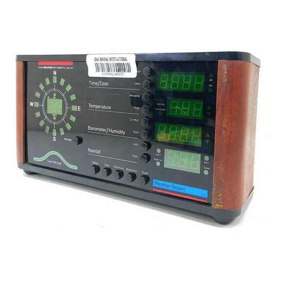
Normal Operation
When in normal operation (no buttons depressed). the instrument displays current wind direction
and speed, cycles current time and date, cycles current indoor, outdoor and if selected, aux
temperatures (if both the indoor and outdoor indicator lights are extinguished, Aux. temperature is
displayed) cycles current barometric pressure, current relative humidity, and cycles daily, monthly
and term cumulative rainfall. By utilizing the hold buttons associated with each display, the user may
select the most important readings to the user. When wind speed in excess of 99 miles per hour are
experienced a small light will turn on between the digits of the wind speed display.
Trend indicators
(arrows) are located to the right of the temperature, relative humidity, and
barometric pressure displays. If, for example, the current relative humidity was increasing the up
trend arrow would be lit. If there was no change, no arrow would be lit.
INSTALLATION
We strongly suggest that all the weather station cables and sensors be connected to the
weather station and tested prior to installation so that you may become familiar with the
operation of the instrument.
The WRL uses three sensors to gather weather data. The wind direction and speed sensor, the
temperature and humidity
a television type mast (not provided). The cables from the sensors go into a
Texas Weather Instruments, Inc.
Weather Report Logger™
Digital Weather Station
WRL-25, WRL-32 & WRL-128
pagoda
and the rain collector (see figure 1). All are designed to mount to
index
/
top
junction
box, where
WRL Instruction Manual
Advertisement

Summary of Contents for Texas Instruments Weather Report Logger WRL-25
- Page 1 WRL Instruction Manual Weather Report Logger™ Digital Weather Station WRL-25, WRL-32 & WRL-128 Thank you for purchasing a Weather Report. Your package should contain a WRL console, wind sensor, temperature/humidity sensor, rain collector serial cable and a diskette that contains the TWI_LOG software.
- Page 2 WRL Instruction Manual they connect via RJ45’s to two multi-wire cables (intermediates) that are routed into the building and attached to the console. All cables are color coded. The yellow wind sensor cable plugs into the yellow RJ45 connector in the junction box. The yellow intermediate (wind) also plugs into a yellow RJ45 connector in the junction box.
- Page 3 WRL Instruction Manual the unit is already mounted, pick a calm day or immobilize the wind vane by hand. Enter calibration mode on the display (see page 9) and step the direction around using the min or max key, or load TWI_LOG program (see page...
-
Page 4: Operation
WRL Instruction Manual OPERATION FUNCTION KEYS index Select The select key, when pressed at the same time as the report key, puts the unit into time/date and lunar/tide cycle set mode. When the select and scale keys are pressed at the same time, the unit enters the calibration set mode. - Page 5 WRL Instruction Manual readings. Scale The scale key changes the displays from reading in English values to those of Metric values. The inch light near the rain display is on when the instrument is in English mode. The English to Metric equivalents are miles per hour or Knots to Kilometers per hour, Fahrenheit to Celsius, Inches of Mercury to Millibars, Inches of rain to Centimeters of rain.
- Page 6 WRL Instruction Manual Press select a second time, and the month will be displayed (i.e., 1 = Jan. and 12 = Dec.). Press the maximum and minimum key to set the month. Press select a third time, and the day of the month (1-31) digits light. Press the maximum to advance the date and minimum to retard the date.
- Page 7 WRL Instruction Manual Press select a fifth time (note the colon between the hours and minutes), and the unit will display the time in military hour style. Press the maximum button to advance the hour or minimum to retard the hour. Press select a sixth time (note the colon between the hours and minutes), and the unit will display minutes.
- Page 8 WRL Instruction Manual Press select a tenth time (the single dot is now located at the top, between the hour and minute); the peak of the cycle hour (usually high tide) will be displayed. Change as desired. Press select an eleventh time (the single dot remains at the top between the hour and minute), and the minutes of the peak hour will be displayed.
- Page 9 WRL Instruction Manual Press select a second time and the unit displays the indoor temperature. Press the maximum or minimum key to enter the actual temperature. Press select a third time - the unit displays the outdoor temperature. Press the maximum or minimum key to enter the actual temperature.
- Page 10 WRL Instruction Manual Press select a fifth time, and the unit displays in the rainfall window: 0, 1, 2, or 3. 2 is the normal display. Press the maximum or minimum key to enter the proper number (see calibration reference, page 23, for more information). Press select a sixth time;...
- Page 11 WRL Instruction Manual indicators are on when in this mode). Logging mode allows the user to view previously logged data via the display. (You can only enter logging mode if there is data in the logging memory). You may choose at what interval of time you would like the data saved through the print set routine (see page 12).
- Page 12 WRL Instruction Manual There are two settings that will affect the deposition of data. The first, report interval , determines how often the WRL will automatically dump data to the RS-232 port. The second, log interval, determines how often the unit saves data to its internal memory. Pressing select and average at the same time puts the unit into print set mode.
- Page 13 WRL Instruction Manual Communicating with the WRL index The WRL via its RS-232 interface can communicate with computers running either the TWI-LOG program or standard computer communication programs. The WRL responds to the following ASCII characters sent by computers, with ASCII space delimited text. Command Characters V- Firmware version number S- Firmware Serial#...
- Page 14 WRL Instruction Manual in 30.04R the “R” denotes rising pressure) Sample 5:15 07/24/90 SSE 04MPH 052F 069F 078F 099% 30.04R 00.19"D 01.38"M 11.78"T r- Unit responds with current conditions. The term rain is present rather than the rainfall rate. (Note: in 30.04F the “F”...
- Page 15 WRL Instruction Manual Pressing selection 3 accesses the WRL via modems and phone lines. WRL access can be modified by editing the twi_com.dat file on your TWI_LOG disk. To change the configuration load twi_com.dat into a text editor and change to your preference. The first station in this example is identified as green.
- Page 16 WRL Instruction Manual at a time, press the page up or down keys to display one screen of data at a time, press the home or end key to go to the top or bottom of the file. The delete key takes all records prior to that displayed at the top of the screen and transfers that data to an archive file arc_log.??? file.
- Page 17 WRL Instruction Manual 7) 2nd humidity sensor calibration factor Wind direction calibration, increase number to move clockwise or decrease number to move counterclockwise. Rain collector type (most rain collectors are type 2 including TWI, 0 turns of the rain collector counter) Rain increment value ( the value that is added for each click of the rain collector, most rain...
- Page 18 WRL Instruction Manual Pressing F6 will graph the data, if you have a VGA monitor. Pressing F7 will take the current binary data file and convert it to a text file. The text file will be named prn_day.??? for the minimums and maximums and prn_rec.??? for the record.
- Page 19 WRL Instruction Manual Knots on AM PM on Aux disable on Instant wind speed on total You may also change these functions via the software program TWI_LOG F5 routine (see page 17). RS-232 Interface The pin out on the RS-232interface is as follows: .DE 9 Plug Header Pin 1...
- Page 20 WRL Instruction Manual Note: The WRL has two separate minimum and maximum memories. Clearing the M command minimum and maximum memory will not affect the C command minimum and maximum memory and vice- versa. The printer/computer memories clear at 12:00 midnight every day and/or when the c key is pressed on the computer console.
- Page 21 WRL Instruction Manual daily rainfall register is zeroed every day at midnight. The monthly rainfall register is zeroed on the last day of each month at midnight. The term rainfall register is never zeroed automatically, it must be manually zeroed through the TWI_LOG calibration routine or by pressing last and clear on the display at the same time.
- Page 22 WRL Instruction Manual Lunar Tide Cycle The lunar tide cycle function may be set to display the position of the moon in relation to its revolution around the earth. The moon's position is the primary, although not the only, factor in predicting high and low coastal tides.
-
Page 23: Fcc Radio Frequency Interference Statement
WRL Instruction Manual FCC RADIO FREQUENCY INTERFERENCE STATEMENT NOTE: This equipment has been tested and found to comply with the limits for a Class B digital device, pursuant to Part 15, Subpart B, of the FCC Rules. This equipment generates, uses, and can radiate radio frequency energy. -
Page 24: Shielded Cable
WRL Instruction Manual The limits are designed to provide reasonable protection against such interference in a residential situation. However, there is no guarantee that interference will not occur in a particular installation. If this equipment does cause interference to radio or television reception, which can be determined by turning the equipment off and on, the user is encouraged to try and correct the interference by one or more of the following measures: * Reorient or relocate the receiving antenna of the affected radio or television... - Page 25 WRL Instruction Manual Check that the rainfall count is set on 2. If you still experience problems, please call (214) 368-7116 and ask for Technical Support, we will be happy to help you. Index arc_log.???, 17 ASCII characters, 13 AT control signals, 21 disable, 19 Average, 6...
- Page 26 WRL Instruction Manual Hold, 5 hours, 19 Humidity Sensor Calibration, 11, humidity sensor calibration factor, 18 number, 19 Inside temperature calibration, 18 INSTALLATION, 2 junction box, 2, 3 Last, 5 logging interval hours, 19 logging interval minutes, 19 Logging Mode, 11 Lunar Tide Cycle, 24, 25 lunar/tide...
- Page 27 WRL Instruction Manual rain collector, 19, Rain collector type, 18 Rain increment value, 19 Rainfall, Rainfall history mode, 25 rainfall rate interval, 19 Report, 5 Report Flag, 23 Report Interval Units, 19 report output, 19 Report output interval HI, 19 Report output interval LO, 19 RS-232,...
Need help?
Do you have a question about the Weather Report Logger WRL-25 and is the answer not in the manual?
Questions and answers