Table of Contents
Advertisement
Quick Links
Advertisement
Chapters
Table of Contents

Related Manuals for Rohde & Schwarz SMBV100B


Summary of Contents for Rohde & Schwarz SMBV100B
- Page 1 ® R&S SMBV100B Vector Signal Generator User Manual (;Ü\Ê2) 1178446002...
- Page 2 ® This document describes the R&S SMBV100B, stock no. 1423.1003.02 and its options: ● ® R&S SMBVB-B103/-KB106 ● ® R&S SMBVB-B1/-B1H ● ® R&S SMBVB-B3 ● R&S ® SMBVB-B32 ● ® R&S SMBVB-B80 ● ® R&S SMBVB-B81 ● R&S ®...
-
Page 3: Safety Instructions
Safety Instructions Instrucciones de seguridad Sicherheitshinweise Consignes de sécurité Risk of injury and instrument damage The instrument must be used in an appropriate manner to prevent electric shock, fire, personal injury or instrument damage. ● Do not open the instrument casing. ●... - Page 4 Gefahr von Verletzungen und Schäden am Gerät Betreiben Sie das Gerät immer ordnungsgemäß, um elektrischen Schlag, Brand, Verletzungen von Personen oder Geräteschäden zu verhindern. ● Öffnen Sie das Gerätegehäuse nicht. ● Lesen und beachten Sie die "Grundlegenden Sicherheitshinweise", die als gedruckte Broschüre dem Gerät beiliegen. ●...
-
Page 5: Table Of Contents
® Contents R&S SMBV100B Contents 1 Preface....................23 Key Features........................23 For Your Safety......................23 About This Manual...................... 24 Documentation Overview................... 25 1.4.1 Getting Started Manual....................25 1.4.2 User Manuals and Help....................25 1.4.3 Service Manual......................26 1.4.4 Instrument Security Procedures..................26 1.4.5 Basic Safety Instructions....................26 1.4.6... - Page 6 "I/Q Stream Mapper" Block................... 72 2.4.7 I/Q Modulator ("I/Q Mod" Block)..................72 2.4.8 Analog I/Q Output ("I/Q Analog" Block).................72 2.4.9 RF and Analog Modulations ("RF" Block)..............73 2.4.10 Applications Examples of the R&S SMBV100B............73 Instrument Control......................73 User Manual 1178.4460.02 ─ 03...
- Page 7 ® Contents R&S SMBV100B 2.5.1 Possible Ways to Operate the Instrument..............73 2.5.2 Means of Manual Interaction..................74 2.5.3 Understanding the Display Information................. 75 2.5.3.1 Status Bar........................75 2.5.3.2 Block Diagram.......................76 2.5.3.3 Taskbar..........................77 2.5.3.4 Additional Display Characteristics.................78 2.5.4 Accessing the Functionality...................79 2.5.5 Entering Data........................
- Page 8 ® Contents R&S SMBV100B 3.4.1.4 Supported Modulation Types..................104 3.4.1.5 Supported Coding Schemes..................105 3.4.1.6 Supported Baseband Filters..................105 Impact of the Filter Parameters...................106 3.4.1.7 Methods for Optimizing the Crest Factor..............107 3.4.2 Common Settings......................109 3.4.2.1 Trigger Settings......................110 3.4.2.2 Marker Settings......................113 3.4.2.3...
- Page 9 ® Contents R&S SMBV100B 3.6.2.3 Waveform Sample Rate....................148 Impact of the Resampling Filter.................. 149 Impact of the Oversampling Factor................149 3.6.2.4 Impact of the Enabled Number of Marker Signals on the Waveform Length....149 3.6.3 ARB Settings.......................150 3.6.3.1 ARB General Settings....................151 3.6.3.2...
- Page 10 ® Contents R&S SMBV100B 3.7.3 Multi-Segment Settings....................199 3.7.3.1 Setting for Handling the Multi-Segment Files and Output File Settings...... 200 3.7.3.2 Segment Table......................202 3.7.3.3 Level / Clock / Marker Settings................... 205 3.7.3.4 Multi-Segment Waveform Sequencing................207 General Settings......................209 Sequencing Play List Settings..................210 3.7.3.5...
- Page 11 ® Contents R&S SMBV100B 3.9.4 How to Use the Multi-Carrier Continuous Wave Function...........248 3.9.5 References........................249 3.10 Shifting and Boosting the Baseband Signal............250 3.10.1 About the Baseband Offsets..................250 3.10.1.1 Impact of the Frequency Offset................... 250 3.10.1.2 Impact of the Phase Offset..................252 3.10.2...
- Page 12 ® Contents R&S SMBV100B Required Options...................... 287 How to Access the RF Settings................287 How to Activate the RF Signal Output..............287 How to Set the Frequency and Level..............288 RF Frequency Settings..................... 289 RF Level Settings...................... 292 RF Phase Settings.....................296 Reference Oscillator....................
- Page 13 ® Contents R&S SMBV100B 6.10.7 List Editor........................341 6.10.8 How to Generate a Signal in List or Sweep Mode............345 6.11 Analog Modulations....................346 6.11.1 Required Options......................346 6.11.2 Modulation Types and Signal Sources................347 6.11.3 Activating Analog Modulations..................348 6.11.4 Modulation Settings.....................349 6.11.4.1...
- Page 14 ® Contents R&S SMBV100B 6.12.4.1 Connecting R&S NRP Power Sensors to the R&S SMBV100B........393 6.12.4.2 NRP Sensor Mapping....................394 6.12.4.3 NRP Power Viewer......................395 About...........................395 NRP Power Viewer Settings..................397 6.12.5 How to Calibrate the Power Level with an R&S NRP Power Sensor......403 7 Monitoring Signal Characteristics............407...
- Page 15 ® Contents R&S SMBV100B 8.4.1.1 Prerequisites for Control of External Instruments from the R&S SMBV100B..... 436 8.4.1.2 Test Setups......................... 436 8.4.1.3 Control of Connected External Instruments..............436 8.4.1.4 Overview of the Input and Output Signals and Interfaces...........436 Overview of the Baseband Signal Sources..............437 Overview of the RF Output Signals................437...
- Page 16 How to Transfer Files from and to the Instrument..........497 9.9.1 Removing File System Protection................498 9.9.2 Accessing the File System of the R&S SMBV100B Via ftp......... 499 9.9.3 Accessing the R&S SMBV100B File System Via SMB (Samba)........ 500 9.9.4 Using a USB Storage Device for File Transfer............502...
- Page 17 ® Contents R&S SMBV100B 10.2.1 Required Options......................515 10.2.2 About the Global Connectors..................515 10.2.2.1 Global Connectors...................... 516 10.2.2.2 Trigger, Marker, Clock and RF Connectors..............516 10.2.2.3 Status Indicators......................517 10.2.3 Trigger Marker Clock Settings..................517 10.2.3.1 Overview Table......................518 10.2.3.2 Global Connector Settings..................519 10.2.4...
- Page 18 ® Contents R&S SMBV100B 11.2.1.2 HiSLIP Protocol......................555 11.2.1.3 VXI-11 Protocol......................555 11.2.1.4 Socket Communication....................555 11.2.2 USB Interface......................556 11.2.2.1 USB Resource String....................556 11.2.3 GPIB Interface (IEC/IEEE Bus Interface)..............557 11.2.4 LXI Browser Interface....................557 11.3 Remote Control Programs and Libraries..............558 11.3.1 VISA Library........................
- Page 19 ® Contents R&S SMBV100B 11.8.4 Setting Up a Remote Control Connection over GPIB..........586 11.8.5 Setting Up a Remote Control Connection over USB...........587 11.9 Tracing SCPI Commands and Messages Exchanged via the LXI Web Browser Interface........................587 11.10 How to Return to Manual Operation................588 11.11...
- Page 20 ® Contents R&S SMBV100B 12.6.1 File Naming Conventions.................... 617 12.6.2 Accessing Files in the Default or in a Specified Directory...........618 12.6.3 Programming Examples....................620 12.6.4 Remote Control Commands..................622 12.7 CALibration Subsystem................... 629 12.8 DIAGnostic Subsystem.................... 632 12.9 DISPlay Subsystem....................634 12.10 FORMat Subsystem....................639 12.11...
- Page 21 ® Contents R&S SMBV100B Save/Recall Settings....................717 Filter Settings......................718 Modulation and Coding Settings................. 720 Power Ramping......................723 Trigger Settings......................725 Marker Settings......................728 Clock Settings......................730 Handling List Files.......................731 12.16.4.3 SOURce:BB:ARBitrary Subsystem................737 Programming Examples....................737 General Commands....................745 Test Signal Commands....................746 Waveform Commands....................749...
- Page 22 ® Contents R&S SMBV100B 12.16.6 SOURce:FREQuency Subsystem................820 12.16.7 SOURce:INPut Subsystem..................829 12.16.8 SOURce:IQ Subsystem....................830 12.16.9 SOURce:IQ:OUTPut Subsystem................832 12.16.9.1 SOURce:IQ:OUTPut:ANALog Commands..............832 12.16.10 SOURce:LFOutput Subsystem................... 837 12.16.10.1 LF Generator Settings....................839 12.16.10.2 LF Sweep Settings...................... 847 12.16.11 SOURce:LIST Subsystem...................850 12.16.11.1 List Mode Settings.......................853...
- Page 23 ® Contents R&S SMBV100B 13.3.5 Selftest Baseband Settings..................937 13.3.6 Selftest Test Generator Settings (DAC)..............937 13.3.7 FPGA/uC Update Settings..................939 13.3.8 Delete Temporary Files....................940 13.3.9 Requesting Instrument Configuration and Specifications........... 941 13.3.9.1 Hardware Configuration Settings................941 13.3.9.2 Versions/Options Settings................... 942 13.3.9.3...
- Page 24 ® Contents R&S SMBV100B Text Parameters......................959 Character Strings......................959 Block Data........................959 A.1.3.4 Overview of Syntax Elements..................959 A.1.3.5 Structure of a Command Line..................961 A.1.3.6 Responses to Queries....................961 A.1.4 Command Sequence and Synchronization..............962 A.1.4.1 Preventing Overlapping Execution................962 A.1.4.2 Examples to Command Sequence and Synchronization..........964 A.1.5...
-
Page 25: Preface
SMBV100B For Your Safety 1 Preface The R&S SMBV100B is a new signal generator developed to meet demanding cus- tomer requirements. Offering excellent signal characteristic and straightforward and intuitive operation, the signal generator makes signal generation fast and easy. 1.1 Key Features Outstanding key features of the R&S SMBV100B are:... -
Page 26: About This Manual
® Preface R&S SMBV100B About This Manual Make sure to comply fully with them. Do not take risks and do not underestimate the potential danger of small details such as a damaged power cable. 1.3 About This Manual This User Manual describes general instrument functions, the operation of the instru- ment and settings common to all firmware options. -
Page 27: Documentation Overview
1.4.1 Getting Started Manual Introduces the R&S SMBV100B and describes how to set up and start working with the product. Includes basic operations, typical measurement examples, and general infor- mation, e.g. safety instructions, etc. A printed version is delivered with the instrument. -
Page 28: Service Manual
The service manual is available for registered users on the global Rohde & Schwarz information system (GLORIS, https://gloris.rohde-schwarz.com). 1.4.4 Instrument Security Procedures Deals with security issues when working with the R&S SMBV100B in secure areas. It is available for download on the Internet. 1.4.5 Basic Safety Instructions Contains safety instructions, operating conditions and further important information. -
Page 29: Application Notes, Application Cards, White Papers, Etc
® Preface R&S SMBV100B Documentation Overview 1.4.8 Application Notes, Application Cards, White Papers, etc. These documents deal with special applications or background information on particu- lar topics. www.rohde-schwarz.com/application/smbv100b User Manual 1178.4460.02 ─ 03... -
Page 30: Getting Started
2.1.1 Putting into Operation This section describes the basic steps to be taken when setting up the R&S SMBV100B for the first time. Risk of injury due to disregarding safety information Observe the information on appropriate operating conditions provided in the data sheet to prevent personal injury or damage to the instrument. -
Page 31: Emi Suppression
Note the EMC classification in the data sheet. 2.1.1.2 Unpacking and Checking the Instrument Unpack the R&S SMBV100B carefully and check the contents of the package. ● Check if all items listed on the delivery note, including this getting started manual, are included in the delivery. -
Page 32: Accessory List
Bench top operation If the R&S SMBV100B is operated on a bench top, the surface must be flat. The instru- ment can be used in horizontal position, standing on its feet, or with the support feet on the bottom extended. - Page 33 ® Getting Started R&S SMBV100B Preparing for Use Risk of injury if feet are folded out The feet can fold in if they are not folded out completely or if the instrument is shifted. Collapsing feet can cause injury or damage the instrument.
-
Page 34: Connecting Ac Power
Preparing for Use Mounting in a rack The R&S SMBV100B can be installed in a rack using a rack adapter kit (Order No. see data sheet). The installation instructions are part of the adapter kit. Risk of instrument damage due to insufficient airflow in a rack If you mount several instruments in a rack, you need an efficient ventilation concept to ensure that the instruments do not overheat. - Page 35 The current setup is saved, the operating system shuts down and sets the instru- ment to standby state. The [On/Standby] LED must be orange. 2. Turn off the main AC power switch at the rear panel of the R&S SMBV100B (posi- tion "0" (off)). The instrument is no longer supplied with AC power.
-
Page 36: Functional Check
"Info" indication. In response, a description of the errors is displayed. For more information, refer to the "Troubleshooting and Error Messages" section in the user manual. In addition to the automatic monitoring, the R&S SMBV100B offers the following capa- bilities to assure correct functioning: ●... -
Page 37: Checking The Supplied Options And Licenses
No access to the operating system is required for normal operation. All necessary system settings can be made in the "Setup" dialog. The R&S SMBV100B provides an internal memory that holds the operating system, the firmware, and the stored data. The folder /var/user and all subfolders can be used to store user data. -
Page 38: Connecting Usb Devices
545. 2.1.3 Connecting USB Devices The USB interfaces of the R&S SMBV100B allow you to connect USB devices, includ- ing USB hubs directly to the instrument. Due to the large number of available USB devices, there is almost no limit to the expansions that are possible with the R&S SMBV100B. -
Page 39: Setting Up A Network (Lan) Connection
A mouse is detected automatically when it is connected. 2.1.4 Setting Up a Network (LAN) Connection The R&S SMBV100B is equipped with a network interface and can be connected to an Ethernet LAN (local area network). Provided the appropriate rights have been assigned by the network administrator, the interface can be used, for example: ●... -
Page 40: Using Computer Names (Hostnames)
By default, the instrument is configured to use DHCP (dynamic host configuration protocol) configuration and to obtain the whole address information automatically. When connected, the R&S SMBV100B displays the address information on the screen. Risk of network connection failure Network cables and cable connectors of poor quality, or failures in the autonegotiation process, can cause network connection failures. -
Page 41: Assigning The Ip Address
You can find the serial number at the rear panel of instrument. It is the third part of the device ID printed on the barcode sticker . Example: The default hostname of an R&S SMBV100B with a serial number 102030 is SMBV100B-102030. To query and change a computer name 1. -
Page 42: Instrument Tour
® Getting Started R&S SMBV100B Instrument Tour Risk of network failure Consult your network administrator before performing the following tasks: ● Connecting the instrument to the network ● Configuring the network ● Changing IP addresses Errors can affect the entire network. -
Page 43: Front Panel Tour
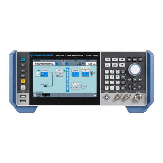
2.2.1 Front Panel Tour This section provides an overview of the control elements and connectors on the front panel of the R&S SMBV100B. On the rear panel, you find all further connectors of the unit, see Chapter 2.2.2, "Rear Panel Tour",... - Page 44 ® Getting Started R&S SMBV100B Instrument Tour Figure 2-2: Touchscreen elements 1 = Status bar (frequency and level display) 2 = Block diagram 3 = Taskbar/softkey bar A touchscreen is a screen that is touch-sensitive. It reacts in a specified way when a particular element on the screen is tapped by a finger.
-
Page 45: Keys
"Cleaning", on page 926. 2.2.1.2 Keys Utility Keys The utility keys cause the R&S SMBV100B to return to a defined instrument state and provide information on the instrument and assistance. For more information, refer to Chapter 10, "General Instrument Functions", on page 509. -
Page 46: Function Keys
® Getting Started R&S SMBV100B Instrument Tour Function Keys Function keys provide access to most common generator settings and functions. A detailed description of the corresponding functions is provided in the user manual. Table 2-2: Function keys Function key Assigned functions [Freq] Activates frequency entry. -
Page 47: Navigation Controls
® Getting Started R&S SMBV100B Instrument Tour Table 2-4: Editing keys Type of key Description [Esc] key Closes all kinds of dialog boxes, if the edit mode is not active. Quits the edit mode, if the edit mode is active. In dialog boxes that contain a "Can- cel"... -
Page 48: Connectors
® Getting Started R&S SMBV100B Instrument Tour Table 2-5: Navigation keys Type of key Description [Up/Down] Key The [Up] and the [Down] key does the following: ● In a numeric edit dialog box, increase or decrease the instrument parameter. ●... -
Page 49: Rear Panel Tour
SMBV100B Instrument Tour A power sensor is connected to the R&S SMBV100B by inserting the male connector. To disconnect, pull the connector by its sleeve. You cannot disconnect the sensor sim- ply by pulling at the cable or the rear part of the connector. -
Page 50: Connectors
® Getting Started R&S SMBV100B Instrument Tour Figure 2-3: Rear panel = Serial number (six digits in the string 1423.1003.02-<serial number>-<checksum>) 2a, 2b = User x connectors = I/Q, I/Q Bar connectors (output) = I/Q connectors (input) = Dig I/Q connector... - Page 51 ® Getting Started R&S SMBV100B Instrument Tour A dedicated LED indicates the connector status: ● Green: an input connector ● Yellow: an output connector ● No light: the connector is not active Chapter 10.2, "Configuring the Global Connectors", on page 515.
- Page 52 ® Getting Started R&S SMBV100B Instrument Tour I and Q inputs for external analog modulation signal directly fed into the I/Q modulator. For more information, see Chapter 8.4.1.4, "Overview of the Input and Output Signals Interfaces", on page 436. Ref In/Ref Out Input/output for external reference signal.
-
Page 53: Trying Out The Instrument
Chapter 2.1.3, "Connecting USB Devices", on page 36. The LAN interface can be used to connect the R&S SMBV100B to a local network for remote control, remote operation, and data transfer. For details, see Chapter 2.1.4, "Setting Up a Network (LAN) Connection",... -
Page 54: Generating An Unmodulated Carrier
We start out by generating a simple unmodulated signal. The R&S SMBV100B in this example can be a base unit in its minimal configuration (i.e. with installed R&S SMBVB-B103). 1. On the R&S SMBV100B front panel, press the Preset key to start out in a defined instrument configuration. 2. Set the frequency: a) On the "Status Bar", tap the "Frequency"... -
Page 55: Generating A Digitally Modulated Signal
The 1.95 GHz signal is output at the RF connector at the front panel of the R&S SMBV100B. ® Connect RF of the R&S SMBV100B to a signal analyzer, for example R&S FSW, to display the generated signal. Figure 2-5: Simplified test setup For the required settings of the signal analyzer, refer to its user manual or its online help. - Page 56 ® Getting Started R&S SMBV100B Trying Out the Instrument The minimum requirement for R&S SMBV100B in this example is a base unit equipped with: ● Option custom digital modulation R&S SMBVB-K520 ● Option frequency R&S SMBVB-B103. The initial situation is not the instrument's preset state but rather the configuration described in Chapter 2.3.1, "Generating an Unmodulated...
- Page 57 ® Getting Started R&S SMBV100B Trying Out the Instrument 4. Select the "Modulation" tab and observe the used "Modulation Type". Figure 2-6: Display of the used modulation type The instrument activates automatically "I/Q Mod", uses the internal trigger and clock signals, and generates a WCDMA-3GPP signal, modulated with a QPSK 45°...
-
Page 58: Triggering The Instrument With An External Signal
2.3.3 Triggering the Instrument with an External Signal The example configurations are rather theoretical cases, because you rarely use the R&S SMBV100B as a standalone instrument. Usually, the instrument would be con- nected to a device under test (DUT) and/or other measurement equipment. As a rule, whenever a test setup requires two or more devices, provide them with a common ref- erence frequency. - Page 59 Trying Out the Instrument To verify the current connector configuration The R&S SMBV100B is equipped with multipurpose bi-directional User connectors. Because the signal direction, input or output, and the signal mapping are configurable, we recommend that you check the current configuration before cabling or further instrument's configurations.
- Page 60 ® Getting Started R&S SMBV100B Trying Out the Instrument Figure 2-8: Signal mapping to the global connectors The "Global Connectors" dialog displays the current connectors configuration. The settings are configurable, but in this example we use the default mapping. 3. Alternatively, select "Block Diagram > Baseband > Misc > Custom Digital Mod", select the "Trigger In"...
- Page 61 ® Getting Started R&S SMBV100B Trying Out the Instrument 3. Select "Global Connector Settings > Routing". 4. For "User 2", select "Direction > Input" and "Signal > Global Trigger". The instrument expects an external global trigger event. In the current configura- tion, the "Global Trigger"...
-
Page 62: Enabling And Configuring A Marker Signal
R&S SMBV100B to the signal analyzer or the DUT. Upon the receiving of an external trigger event, the R&S SMBV100B starts the sig- nal generation and then generates a continuous signal. An "Arm" stops the signal generation. A subsequent trigger event causes a restart of the signal generation. -
Page 63: Verifying The Generated Signal With The Graphics Display
User 1 connector of the R&S SMBV100B (see Figure 2-8). 3. Use a suitable cable to connect the User 1 connector of the R&S SMBV100B to the ® monitoring instrument, for example oscilloscope like R&S RTO. See Figure 2-10. - Page 64 SMBV100B Trying Out the Instrument The R&S SMBV100B provides a build-in function to represent the generated signal on a graphical signal display. We demonstrate this feature by showing the characteristics at one particular point of the signal processing chain. You can, however, display the signal characteristics at other different stages.
- Page 65 ® Getting Started R&S SMBV100B Trying Out the Instrument A new thumbnail (minimized view) indicating the active diagram appears in the "Taskbar". 4. Press the thumbnail graphic. The graphic enlarges and the diagram is displayed in a normal size. The "Constellation Diagram" displays the 3GPP FDD signal.
-
Page 66: Saving And Recalling Settings
® Getting Started R&S SMBV100B Trying Out the Instrument This action has no effect on the configured graphics but on the dialog itself. The block diagram displays the current signal routing. It indicates that frequency and power offsets are enabled and displays the acquisition points for the real-time diagrams minimized in the "Taskbar". - Page 67 ® Getting Started R&S SMBV100B Trying Out the Instrument 3. Tap the "Save" button. The file MyTestSignal.savrcltxt is saved in the default directory /var/user. To load saved instrument settings You can restore the settings to the instrument at any time using the settings file.
- Page 68 ® Getting Started R&S SMBV100B Trying Out the Instrument 4. Tap the "Recall" button. All instrument settings are restored and the display resembles the instrument dis- play right before the settings were saved. How to display all parameters with values different to their preset values...
-
Page 69: Generating An Eutra/Lte Signal
We use one of the provided EUTRA test models (E-TM) to show how to generate a test signal upon a quick selection. 1. On the R&S SMBV100B front panel, press the Preset key to start out in a defined instrument configuration. - Page 70 ® Getting Started R&S SMBV100B Trying Out the Instrument The more complex the digital standard itself is, the more comprehensive the further dialog and tab structure. The start dialog of each digital standard, however, follows a repeating dialog structure that comprises the tabs "General", "Trigger In", "Marker"...
- Page 71 With these first steps, you have gained an impression of the provided functionality. For a comprehensive description of the full range of capabilities, refer to the user man- ual "EUTRA/LTE Digital Standard for R&S SMBV100B". User Manual 1178.4460.02 ─ 03...
-
Page 72: System Overview
System Overview 2.4 System Overview This section helps you to get familiar with the R&S SMBV100B. It provides an introduc- tion to the general concept of the instrument. This section also introduces the main blocks in the signal generation flow. -
Page 73: Internal Baseband Source ("Baseband" Block)
The information assumes R&S SMBV100B base unit. For exact information on the available options, and on the minimum requirements and the interdependencies between the provided options, refer to the R&S SMBV100B data sheet. Table 2-10: Required options per functional block (excerpt) -
Page 74: Digital Baseband Input ("Bb Input"Block)
® Getting Started R&S SMBV100B System Overview ● The baseband offsets function Signals from the baseband generator can be shifted in frequency and phase, or boosted in power. 2.4.4 Digital Baseband Input ("BB Input"Block) The "BB Input" block is the access point to the settings of: ●... -
Page 75: Possible Ways To Operate The Instrument
● Generation of digitally modulated signal The main field of application of the R&S SMBV100B is the generation of digitally modulated signals. The R&S SMBV100B generates a digitally modulated signal in several ways: using the internal baseband generator, using the externally applied digital baseband signals or in an analog wideband I/Q operation. -
Page 76: Instrument Control
"Remote Operation over VNC", on page 84. 2.5.2 Means of Manual Interaction For the manual interaction with the R&S SMBV100B, you have several methods that you can use as an alternative to perform a task: ● Touchscreen: Touchscreen operation is the most direct way to interact. Almost all control ele- ments and actions on the screen are based on the standard operating system con- cept. -
Page 77: Understanding The Display Information
SMBV100B Instrument Control 2.5.3 Understanding the Display Information The block diagram of the R&S SMBV100B displays all main settings and generator states, divided into three main operation areas. Figure 2-11: Block diagram 1 = Status bar (frequency and level display) -
Page 78: Block Diagram
® Getting Started R&S SMBV100B Instrument Control Underlined names are touch-sensitive. By touching them, you can execute a setting or access the dialog or menu. 2.5.3.2 Block Diagram The block diagram shows the current configuration and the signal flow in the generator with the aid of function blocks, connected by signal lines. -
Page 79: Taskbar
® Getting Started R&S SMBV100B Instrument Control Legend Item Description 4, 6 Signal lines (digital/ analog) Show the currently configured signal flow. ● Thick lines represent the digital I/Q streams, see (4) in the figure above ● Thin lines represent the analog signals (6) Graphics indicator Denotes that the signal is displayed graphically (5a/5b). -
Page 80: Additional Display Characteristics
® Getting Started R&S SMBV100B Instrument Control Dialogs Shows a dialog as a thumbnail, the dialog name, and the name of signal channel. Diagram / More The diagram icon as shown in Figure 2-12 minimizes all dialogs indicated on the screen. The block diagram is in the foreground. -
Page 81: Accessing The Functionality
® Getting Started R&S SMBV100B Instrument Control 2.5.4 Accessing the Functionality All functionalities are provided in dialog boxes as known from computer programs. You can control the instrument intuitively with the touchscreen. This section provides an overview of the accessing methods. -
Page 82: Entering Data
® Getting Started R&S SMBV100B Instrument Control To close a dialog box To close a dialog box, you have the same controls as you know from computers or devices with touchscreen. ► Perform one of the following actions: ● Tap the "Close" icon in the upper right corner. -
Page 83: Entering Numeric Parameters
® Getting Started R&S SMBV100B Instrument Control Completing the entry ► Press the [Enter] key or the rotary knob. Aborting the entry ► Press the [Esc] key. The dialog box closes without changing the settings. 2.5.5.1 Entering Numeric Parameters To enter values with the on-screen keypad For numeric settings, the instrument displays the numeric keypad. -
Page 84: Getting Information And Help
® Getting Started R&S SMBV100B Instrument Control "Redo" restores a previously undone action. 2.5.6 Getting Information and Help In some dialog boxes, graphics are included to explain the way a setting works. For further information, you can use the following sources: ●... -
Page 85: Remote Control
The corresponding help topic is displayed. 2.5.7 Remote Control In addition to working with the R&S SMBV100B interactively, located directly at the instrument, it is also possible to operate and control it from a remote PC. The R&S SMBV100B supports various methods for remote control: ●... -
Page 86: Remote Operation Over Vnc
Thus, remote operation of the instrument is possible. Instrument control from a remote computer To access the basic utility functions of the R&S SMBV100B, perform a right mouse click on the block diagram and select "Key Emulation". A key panel to the right of the block diagram gives access to the utility functions provi- ded by the front panel keys. -
Page 87: Configuring The Internal Baseband Source
Overview of the Signal Generation Modes 3 Configuring the Internal Baseband Source The R&S SMBV100B is a vector signal generator with internal signal generation and real-time functionality and with integrated arbitrary waveform generator. The instrument enables you to generate various digital modulation signals in accord- ance with the definitions in the corresponding specifications or with user-definable characteristics. -
Page 88: How To Access The Functions In The Baseband Domain
® Configuring the Internal Baseband Source R&S SMBV100B How to Access the Functions in the Baseband Domain Waveforms can be generated for example with the signal generation software ® R&S WinIQSIM2 or the R&S Pulse Sequencer software. ● The instrument provides different functions to generate waveforms Internally. -
Page 89: Generating Signals According To Digital Standards
Signal", on page 250 3.3 Generating Signals According to Digital Standards The R&S SMBV100B generates digital signals in accordance with the specifications of the main communication and radio standards only if the corresponding firmware options are installed. GSM/EDGE, EDGE Evolution This digital standard requires an instrument equipped with the GSM/EDGE and EDGE Evolution options R&S SMBVB-K40/-K41. - Page 90 The 1xEV-DO options provide functionality to generate signals in accordance with the CDMA2000 1xEV-DO (Evolution-Data Optimized), Rev. A and Rev. B standard. For details, see the R&S SMBV100B 1xEV-DO Rev. A Rev. B user manual. IEEE 802.11a/b/g/n, IEEE 802.11ac, IEEE 802.11ax This digital standard requires an instrument equipped with the IEEE 802.11a/b/g/n and...
-
Page 91: Data, Clock And Control Signals And Sources In The Baseband
This option provides functionality to generate signals in accordance with the 3GPP standard New Radio Rel. 15. For details, see the R&S SMBV100B 5G New Radio user manual. OFDM Signal Generation This functionality requires an instrument equipped with the OFDM signal generation option R&S SMBVB-K114. -
Page 92: Internal Modulation Data
Chapter 10.2, "Configuring the Global Connectors", on page 515. Internal Modulation Data The R&S SMBV100B uses the following internal modulation data sources: ● Data lists Data lists are externally or internally created binary lists with modulation data. The instrument provides standard file select function for loading of existing data lists, creating internally new data lists or editing an existing one. -
Page 93: Clock Signals
® Configuring the Internal Baseband Source R&S SMBV100B Common Functions and Settings in the Baseband Domain The pseudo-random sequence from a PRBS generator is uniquely defined by the register number and the feedback. The Table 3-1 describes the available PRBS generators. -
Page 94: Control Signals
The CW/Mod control signal is generated internally and is output at one of the User x connectors. Power Ramping and Level Attenuation The R&S SMBV100B uses the two control signals "Burst Gate" and "Lev_Att" to trigger the power ramping and level attenuation functions. The instrument internally generates control signals as configured in Chapter 3.5.3.8,... - Page 95 ® Configuring the Internal Baseband Source R&S SMBV100B Common Functions and Settings in the Baseband Domain the steepness of this ramp, see "Impact of the Power Ramping Settings on the Generated Signal" on page 93. ● Level attenuation control signal The "Lev_Att"...
-
Page 96: Regular Marker Output Signals
3.4.1.2 Regular Marker Output Signals The R&S SMBV100B can add additional signals to the generated signal. Marker sig- nals (or markers) are digital signals which can be used to synchronize external devices to the generated data stream. For example, with suitable marker settings, a slot clock or frame clock can be selected, or the start of a particular modulation symbol can be marked. - Page 97 ® Configuring the Internal Baseband Source R&S SMBV100B Common Functions and Settings in the Baseband Domain time. This marker can be used to monitor the effects of the selected trigger, e.g. trigger causing restarts of the signal generation. Marker mode pulse Periodic marker with consecutive On and Off periods of equal length.
-
Page 98: Baseband Trigger Signals
This is not one of the most common modes. The instrument generates a marker signal that is defined in the selected control list. The R&S SMBV100B provides a graphical interface for convenient definition of control signals among others also for the marker signals. -
Page 99: Trigger Sources
® Configuring the Internal Baseband Source R&S SMBV100B Common Functions and Settings in the Baseband Domain Trigger event A trigger event is caused by the received trigger signal. Another possibility to provoke a trigger event is to execute trigger manually. The "Arm" function stops the signal gener- ation until subsequent trigger event occurs. - Page 100 ® Configuring the Internal Baseband Source R&S SMBV100B Common Functions and Settings in the Baseband Domain Table 3-3: Impact of the trigger events on the generated signal "Trigger Mode" Signal generation Trigger event Trigger event mode "Exec. Trigger" or "External"...
- Page 101 ® Configuring the Internal Baseband Source R&S SMBV100B Common Functions and Settings in the Baseband Domain Figure 3-4: Trigger mode single ** = the signal is generated once to the length specified with "Trigger Signal Duration" ● Auto In auto trigger mode, the instrument generates a continuous signal.
-
Page 102: Impact Of The Additional Trigger Settings
An "Arm" stops the signal generation. A subsequent trigger event causes a restart. Figure 3-8: Trigger mode armed retrigger Impact of the Additional Trigger Settings The R&S SMBV100B provides a set of settings to configure the behavior upon receiv- ing of a trigger signal. For example: ●... - Page 103 The following trigger settings enhance the flexibility of the trigger system and can help to avoid accidental trigger events. ● "Threshold Trigger Input" Defines the voltage level of the trigger signal where the R&S SMBV100B gener- ates a trigger event. Trigger signals below the trigger threshold are ignored. ● "Trigger Input Slope"...
- Page 104 ® Configuring the Internal Baseband Source R&S SMBV100B Common Functions and Settings in the Baseband Domain ● "(External) Trigger Delay" You can apply a definable number of symbols to delay the start trigger event of an externally supplied trigger signals This feature is useful to: –...
-
Page 105: Receiving And Providing Trigger Signals
® Configuring the Internal Baseband Source R&S SMBV100B Common Functions and Settings in the Baseband Domain Example: This example is based on an ARB signal with 1 MHz clock frequency ("Baseband > ARB > Clock Frequency = 1 MHz"). Step 1: Enable the following settings: ●... -
Page 106: Supported Modulation Types
3.4.1.4 Supported Modulation Types The R&S SMBV100B supports a range of predefined digital and analog modulation types. This section focuses on the possibility to digitally modulate the baseband signal. The analog modulation methods provided for shifting the frequency bandwidth of the RF signal are described in Chapter 6.11, "Analog... -
Page 107: Supported Coding Schemes
The filter wizard (filtwiz) is a tool from Rohde & Schwarz designed for creating filter files that can be imported on a R&S SMBV100B. Its main purpose is the conversion of user-defined finite impulse response (FIR) filters into the filter format (*.vaf). Beyond this filtwiz provides designs for standard filters, e.g. -
Page 108: Impact Of The Filter Parameters
® Configuring the Internal Baseband Source R&S SMBV100B Common Functions and Settings in the Baseband Domain For more information, refer to the description "Introduction to "filtwiz" Filter Editor" at the Rohde & Schwarz webpage. The remote commands required to define the filter settings are described in Chap- ter 12.16.4.2, "SOURce:BB:DM... -
Page 109: Methods For Optimizing The Crest Factor
® Configuring the Internal Baseband Source R&S SMBV100B Common Functions and Settings in the Baseband Domain Cut Off Frequency Shift The "Cut Off Frequency Shift" affects the cut-off frequency in the way that the filter flanks are "moved" and the passband increases by "Cut Off Frequency Shift"*"Sample Rate":... - Page 110 Common Functions and Settings in the Baseband Domain Direct approaches At the individual signal generation stages, the R&S SMBV100B offers different direct approaches aimed to reduce the crest factor. While the corresponding parameters are enabled, the implemented algorithms ensure minimizing the crest factor or achieving of predefined target crest factor by applying of automatic settings.
-
Page 111: Common Settings
® Configuring the Internal Baseband Source R&S SMBV100B Common Functions and Settings in the Baseband Domain Example: The following figures demonstrate the effect of the clipping on the crest factor for typi- cal scenarios. Enabled is clipping with vector mode (|I+q|), using a signal configuration with 2 active channels. -
Page 112: Mode
® Configuring the Internal Baseband Source R&S SMBV100B Common Functions and Settings in the Baseband Domain Routing and enabling a trigger The provided trigger signals are not dedicated to a particular connector. Trigger signals can be mapped to one or more User x connectors. -
Page 113: Signal Duration
® Configuring the Internal Baseband Source R&S SMBV100B Common Functions and Settings in the Baseband Domain Refer to "Impact of the Trigger Modes on the Signal Generation" on page 97 for a detailed description of the provided trigger modes. Remote command: on page 725 [:SOURce<hw>]:BB:DM[:TRIGger]:SEQuence... -
Page 114: Sync. Output To External Trigger/Sync. Output To Trigger
® Configuring the Internal Baseband Source R&S SMBV100B Common Functions and Settings in the Baseband Domain The trigger event is the active edge of an external trigger signal provided and con- figured at the User x connectors. ● "Baseband Sync In"... -
Page 115: (Specified) External Delay/(Specified) Trigger Delay
® Configuring the Internal Baseband Source R&S SMBV100B Common Functions and Settings in the Baseband Domain See also "Specifying delay and inhibit values in time units" on page 102. Remote command: on page 727 [:SOURce<hw>]:BB:DM:TRIGger:DELay:UNIT on page 775 [:SOURce<hw>]:BB:ARBitrary:TRIGger:DELay:UNIT (Specified) External Delay/(Specified) Trigger Delay... - Page 116 ® Configuring the Internal Baseband Source R&S SMBV100B Common Functions and Settings in the Baseband Domain Settings: Marker Mode....................... 114 Marker x Delay......................114 Marker Mode Basic marker configuration for up to three marker channels. The contents of the dialog change with the selected marker mode.
-
Page 117: Clock Settings
Each of the "Trigger In", "Marker" and "Clock" dialogs as well as the "Trigger Marker Clock" dialog provides a quick access to the related connector settings. For more information, refer to the description R&S SMBV100B user manual, section "Global Connector Settings". -
Page 118: Generating Custom Digital Modulated Signals
An inappropriate change of a parameter triggers a settings conflict, which is indicated by a message on the "Info" line in the display. Although the R&S SMBV100B displays the selected settings, the generated modulation signal does not correspond to this dis- play. -
Page 119: Settings
® Configuring the Internal Baseband Source R&S SMBV100B Generating Custom Digital Modulated Signals The dialog is divided into several tabs. In each case, the current setting is dis- played in the tab name. The remote commands required to define these settings are described in Chap- ter 12.16.4.2, "SOURce:BB:DM... -
Page 120: State
® Configuring the Internal Baseband Source R&S SMBV100B Generating Custom Digital Modulated Signals Symbol Rate........................119 Coding......................... 119 Power Ramp Control....................119 State Enables/disables digital modulation. Switching on digital modulation turns off all other digital standards. The digital modulation is generated in real time (no precalculated signal), and therefore while the digital modulation is enabled, all parameter changes directly affect the output signal. -
Page 121: Setting
® Configuring the Internal Baseband Source R&S SMBV100B Generating Custom Digital Modulated Signals Symbol Rate Selects the symbol rate. The value range of this parameter depends on the selected modulation type; the range is automatically redefined. An error message appears if the selected symbol rate is outside of the redefined range. - Page 122 ® Configuring the Internal Baseband Source R&S SMBV100B Generating Custom Digital Modulated Signals Settings: Data Source........................ 120 Select Data List......................121 Select Control List....................... 121 Connector Settings......................121 Data Source Selects the data source (see Chapter 3.4.1.1, "Data, Clock and Control Signals and Sources in the Baseband",...
-
Page 123: Modulation Settings
® Configuring the Internal Baseband Source R&S SMBV100B Generating Custom Digital Modulated Signals Select Data List Accesses the standard "Select List" dialog to select an existing data list or to create a new one. Data lists can be generated externally or internally in the data editor. - Page 124 ® Configuring the Internal Baseband Source R&S SMBV100B Generating Custom Digital Modulated Signals This tab provides access to the modulation settings, e.g modulation type, FSK devia- tion, or modulation depth. The dialog shows the theoretical constellation diagram of the selected modulation.
- Page 125 ® Configuring the Internal Baseband Source R&S SMBV100B Generating Custom Digital Modulated Signals Load User Mapping Accesses the "Select List File User Mapping" dialog to select the mapping table (see "User mapping" on page 104). The dialog provides all standard file management func- tions.
-
Page 126: Filter Settings
® Configuring the Internal Baseband Source R&S SMBV100B Generating Custom Digital Modulated Signals Deviation xxxx For "Variable FSK", sets the deviation of the associated symbol. The number of sym- bols depends on the selected modulation type. The value of each symbol is indicated in binary format. - Page 127 ® Configuring the Internal Baseband Source R&S SMBV100B Generating Custom Digital Modulated Signals Settings: Filter..........................125 Filter Parameter......................125 Cutoff Frequency Factor....................125 Bandwidth........................126 Load User Filter......................126 Filter Selects the baseband filter. Refer to Chapter 3.5.5.2, "Predefined Baseband Filters", on page 142 for overview of the available filter types, their filter shapes and filter parameters.
-
Page 128: Power Ramp Control Settings
® Configuring the Internal Baseband Source R&S SMBV100B Generating Custom Digital Modulated Signals Remote command: on page 718 [:SOURce<hw>]:BB:DM:FILTer:PARameter:LPASs on page 718 [:SOURce<hw>]:BB:DM:FILTer:PARameter:LPASSEVM on page 718 [:SOURce<hw>]:BB:DM:FILTer:PARameter:APCO25Lsm:GAUSs on page 718 [:SOURce<hw>]:BB:DM:FILTer:PARameter:APCO25Lsm:LOWPass Bandwidth Determines the bandwidth of the cosine filter, so that the function in H(f) = 0 is fulfilled for f >= (1 + Rolloff)* Bandwidth /2. -
Page 129: Source
® Configuring the Internal Baseband Source R&S SMBV100B Generating Custom Digital Modulated Signals The dialog comprises the settings used to configure the power ramping, like the source of the control signals, the form of the ramp function and the applied attenuation. -
Page 130: Data List Editor
724 [:SOURce<hw>]:BB:DM:PRAMp:BBONly[:STATe] 3.5.3.7 Data List Editor The R&S SMBV100B provides the following ways to create a data list file: ● To use the dedicated "Data List Editor" and create a file with extension *.dm_iqd, "To create data lists manually"... - Page 131 ® Configuring the Internal Baseband Source R&S SMBV100B Generating Custom Digital Modulated Signals ● To use SCPI commands and create a file in binary format, see "To create a data list in binary format" on page 176. Access: 1. Select "Baseband > Custom Digital Mod > Data Source > Data List".
-
Page 132: Control And Marker Lists Editor
Accesses a virtual keyboard to enter Hex/Bin values. 3.5.3.8 Control and Marker Lists Editor The R&S SMBV100B provides the following ways to create a file containing control sig- nals: ● To use the tag-oriented format and create a control list file, see "To create a control... - Page 133 ® Configuring the Internal Baseband Source R&S SMBV100B Generating Custom Digital Modulated Signals 5. Select "Edit". The dedicated internal "Control Data Editor" is an intuitive graphical interface provi- ded for defining and managing of: ● Marker signals ● Control signals, like the CW, "Hop", "Burst Gate", and "Lev_Att" control signals (see also "Control Signals"...
- Page 134 ® Configuring the Internal Baseband Source R&S SMBV100B Generating Custom Digital Modulated Signals Preset Type......................... 132 Cursor Position......................133 Positions Control Signal....................133 Zoom/Visible........................133 Save/Save As......................134 Configure Control Signal Displays the color the marker/control signal has been assigned. The status checkbox indicates whether the individual marker or control signal is assigned or enabled (see Chapter 3.5.4.1, "How to Create and Assign a Control...
- Page 135 ® Configuring the Internal Baseband Source R&S SMBV100B Generating Custom Digital Modulated Signals "Ramp Up/Down, Ramp Down/Up" Created is a ramp sequence of low to high and high to low transitions, respectively high to low, and low to high transitions. The ramps are symmetrically distributed around the center of the displayed signal area but be later shifted as required.
-
Page 136: How To Create Data And Control Lists
Digital Modulation Settings", on page 116. 3.5.4.1 How to Create and Assign a Control List The R&S SMBV100B provides the following ways to create a file containing control sig- nals: ● To use the dedicated Control and Marker Lists Editor and create a file in ASCII for- mat and with extension *.dm_iqc, see... - Page 137 To use a marker/control signal from a control list and to output this signal at the suppor- ted connector, perform the following: 1. Enable the R&S SMBV100B to use the control list for marker output 2. Output this signal at the User2 connector:...
-
Page 138: How To Create And Assign A Data List
Select "User 2 > Direction = Output", "User 2 > Signal = Baseband Marker 2". 2. To enable the R&S SMBV100B to use the Burst Gate and Level Attenuation control signals as defined in a control list and output one of them at the User3 connector: a) Select "Baseband >... -
Page 139: References
Select "Select Data List" c) Navigate through the file system. Select the file and confirm with "Select". 2. To enable the R&S SMBV100B to use the data list as data source for any of the digital standards: a) Select the "Data List Name" in the individual dialog. -
Page 140: State
® Configuring the Internal Baseband Source R&S SMBV100B Generating Custom Digital Modulated Signals Parameter Value Standard Symbol Rate 270.833 ksymb/s Coding Modulation Type Filter Gauss (FSK) Filter Parameter BxT Trigger Mode Auto, Source Internal Clock Source Internal Power Ramp Control... - Page 141 ® Configuring the Internal Baseband Source R&S SMBV100B Generating Custom Digital Modulated Signals Standard Modulation Symbol Rate Filter Coding Parameter for SCPI command Bluetooth 2FSK, Deviation 1.0 Msym/s Gauss, B*T = 0.5 BLUetooth 160.0 kHz DECT 2FSK, Deviation 1.152 Msym/s Gauss, B*T = 0.5...
-
Page 142: Common Coding Algorithms
® Configuring the Internal Baseband Source R&S SMBV100B Generating Custom Digital Modulated Signals Differ- Phase Diff. Gray NADC, TFTS/ INMARSAT, APCO25 APCO25 ential Diff. +Gray PDC, TETRA ICO, (FSK) (8PSK) PHS, WCDMA, TETRA, cdma2000 APCO25 (PSK), AQPSK OQPSK 8PSK_EDGE Pi/8 D8PSK... - Page 143 ® Configuring the Internal Baseband Source R&S SMBV100B Generating Custom Digital Modulated Signals Table 3-8: Common coding algorithms Coding Coding algorithm Applicable for Required option K bit/symbol "None" k = 1...8 "Differential" k = 1...7 = (a ) modulo 2 –1...
-
Page 144: Predefined Baseband Filters
® Configuring the Internal Baseband Source R&S SMBV100B Generating Custom Digital Modulated Signals Example: Differential coding for modulation type pi/4DQPSK With differential coding switched on at the same time, the obtained constellation dia- gram for pi/4DQPSK is similar to that of 8PSK. Phase shifts are however assigned to the individual modulation symbols. - Page 145 ® Configuring the Internal Baseband Source R&S SMBV100B Generating Custom Digital Modulated Signals Table 3-12: Overview of the baseband filters Cosine (raised cosine) Root cosine (root raised cosine (RRC)) Gauss (FSK) Rolloff factor Rolloff factor Bandwidth Pure gauss Gauss linearized...
- Page 146 ® Configuring the Internal Baseband Source R&S SMBV100B Generating Custom Digital Modulated Signals APCO25 APCO25 (H-CPM) APCO25 (LSM) Rolloff factor Gauss cutoff frequency Split Phase Rectangular Dirac User Manual 1178.4460.02 ─ 03...
-
Page 147: Using The Arbitrary Waveform Generator (Arb)
The Arbitrary Waveform Generator (ARB) is an I/Q modulation source forming part of the R&S SMBV100B. The ARB allows the playback and output of any externally calcu- lated modulation signals in the form of waveform files. The ARB can also generate multi-carrier or multi-segment signals from the waveform files. -
Page 148: Waveform Files Sources
3.6.2.1 Waveform Files Sources In ARB mode, the R&S SMBV100B uses ARB waveform files to obtain the digital I/Q data of the baseband signal. The R&S SMBV100B can replay any waveform file stored on a network drive but it can also generate and replay simple waveforms for test pur- poses. -
Page 149: Arb Test Signals
® Configuring the Internal Baseband Source R&S SMBV100B Using the Arbitrary Waveform Generator (ARB) GPIB). Usually, the waveform file is stored on one of the network drives which are accessible for the operating system. Related settings See: ● Chapter 3.6.3, "ARB Settings",... -
Page 150: Waveform Sample Rate
® Configuring the Internal Baseband Source R&S SMBV100B Using the Arbitrary Waveform Generator (ARB) In general the I/Q samples are located on a deformed circle which is confined to the dashed square in the upper diagrams. ● Rect Test Signal: Rectangle signal with selectable but equal On and Off periods and amplitude. -
Page 151: Impact Of The Resampling Filter
Impact of the Enabled Number of Marker Signals on the Waveform Length The R&S SMBV100B provides the possibility to define marker signals, that are sent to the marker outputs in synchronicity with the I/Q output signals. Marker signals can be either predefined or subsequently defined. -
Page 152: Arb Settings
Configuring the Internal Baseband Source R&S SMBV100B Using the Arbitrary Waveform Generator (ARB) Example: Calculating the maximum waveform length The calculation in this example assumes R&S SMBV100B equipped with option R&S SMBVB-K511 (256 Msamples). ● Total Memory Size = 256 MB ●... -
Page 153: Arb General Settings
® Configuring the Internal Baseband Source R&S SMBV100B Using the Arbitrary Waveform Generator (ARB) 3.6.3.1 ARB General Settings Access: ► Select "Baseband > ARB". This tab provides access to the default ARB settings, selecting a waveform file and enabling the ARB generator. -
Page 154: State
® Configuring the Internal Baseband Source R&S SMBV100B Using the Arbitrary Waveform Generator (ARB) Create Test Signal.......................154 Test Signal Form......................154 RF Power Ramping with Burst Marker................154 State Enables/disables ARB modulation. Switching on the ARB generator turns off all the other digital standards and digital modulation types in the same signal path. -
Page 155: Waveform Info
® Configuring the Internal Baseband Source R&S SMBV100B Using the Arbitrary Waveform Generator (ARB) The waveform files are files with predefined file extension *.wv. When a file is selected, the dialog displays short information about the selected waveform. Enable the ARB generator ("ARB > State > On") to trigger the instrument to load and process the selected waveform file. -
Page 156: Create Multi Carrier
® Configuring the Internal Baseband Source R&S SMBV100B Using the Arbitrary Waveform Generator (ARB) Create Multi Carrier Accesses the dialog for creating multi-carrier waveforms (see Chapter 3.8, "Generating Multi-Carrier Signals", on page 223). Create Test Signal... Opens the dialog with further setting for the selected... -
Page 157: Sine Test Signals
® Configuring the Internal Baseband Source R&S SMBV100B Using the Arbitrary Waveform Generator (ARB) 3.6.3.2 Sine Test Signals Access: ► Select "Baseband > ARB > General > Create Test Signal > Sine" and press "Cre- ate Test Signal". This dialog provides settings for configuration of a sinusoidal test signal. A sine wave is generated on the I path, and a sine wave of the same frequency but phase-shifted is generated on the Q path. -
Page 158: Rectangular Test Signal
® Configuring the Internal Baseband Source R&S SMBV100B Using the Arbitrary Waveform Generator (ARB) Remote command: on page 748 [:SOURce<hw>]:BB:ARBitrary:TSIGnal:SINE:SAMPles Phase Offset Q Enters the phase offset of the sine-wave signal on the Q channel relative to the sine- wave signal on the I channel. - Page 159 ® Configuring the Internal Baseband Source R&S SMBV100B Using the Arbitrary Waveform Generator (ARB) This dialog provides settings for configuration of a rectangular test signal. A rectan- gular test signal with a duty factor of 0.5 is created. Amplitude and offset are adjustable.
-
Page 160: Constant Iq Test Signal
® Configuring the Internal Baseband Source R&S SMBV100B Using the Arbitrary Waveform Generator (ARB) Remote command: on page 749 [:SOURce<hw>]:BB:ARBitrary:TSIGnal:SINE:CREate 3.6.3.4 Constant IQ Test Signal Access: 1. Select "Baseband > ARB > General > Create Test Signal > Const IQ". -
Page 161: Trigger, Marker And Clock Setting
® Configuring the Internal Baseband Source R&S SMBV100B Using the Arbitrary Waveform Generator (ARB) Remote command: on page 749 [:SOURce<hw>]:BB:ARBitrary:TSIGnal:CIQ:CREate:NAMed Generate Signal RAM Generates a signal and uses it as output straight away. The instrument stores the file with a predefined name. -
Page 162: How To Create, Generate And Play Waveform Files
Format", on page 167. Provided the R&S SMBV100B is equipped with the required option, you can load this waveform file and subsequent process it with the instrument. This section provides examples on the internal waveform file generation and on the external generation with the R&S WinIQSIM2. -
Page 163: How To Create Waveform Files With The Built-In Generate Waveform File Function
Navigate through the directory tree (e.g. /var/user/). Enter a filename (e.g. lte_waveform) . Select "Save" The R&S SMBV100B stores the generated waveform file lte_waveform.wv under the selected directory /var/user/. To process the waveform file, load it in the ARB (see Chapter 3.6.4.3, "How to... -
Page 164: How To Create A Waveform File With The R&S Winiqsim2 And Load It In The Arb
The following is an example on how to use the R&S WinIQSIM2 to generate an EUTRA/LTE waveform and load it in the ARB of the R&S SMBV100B. The workflow consists of three main steps, each described in a separate step-by-step instruction: ●... - Page 165 4. Close the dialog. 5. In the block diagram, select "Vector Sig Gen" block and select the R&S SMBV100B form the list. 6. In the block diagram, select "ARB Sig Gen" block and select the R&S SMBV100B form the list.
- Page 166 ® Configuring the Internal Baseband Source R&S SMBV100B Using the Arbitrary Waveform Generator (ARB) To generate a waveform file with the R&S WinIQSIM2 1. In the block diagram of R&S WinIQSIM2, select "Baseband > EUTRA/LTE/IoT". 2. Adjust the settings as required, for example: a) select "Link Direction >...
- Page 167 ® Configuring the Internal Baseband Source R&S SMBV100B Using the Arbitrary Waveform Generator (ARB) The R&S WinIQSIM2 calculates the signal and displays important signal parame- ters, like the used "Sample Rate" and "Number of Samples". User Manual 1178.4460.02 ─ 03...
- Page 168 The display confirms the expected EUTRA/LTE 10 MHz spectrum. To transfer the generated file to the R&S SMBV100B 1. In the R&S WinIQSIM2, select "Transmission > Transmit". 2. In the "Waveform Transmission to Arbitrary Waveform Generator" dialog, select: a) "Transmit from >...
-
Page 169: How To Manually Create A Waveform Using Tag File Format
SMBV100B Using the Arbitrary Waveform Generator (ARB) The waveform is transmitted to the default directory of the R&S SMBV100B. 3. In the R&S SMBV100B, select "Baseband > ARB". The dialog confirms that the ARB is enabled and plays the transmitted waveform. - Page 170 ® Configuring the Internal Baseband Source R&S SMBV100B Using the Arbitrary Waveform Generator (ARB) datory tags are added and the data is packed into the WAVEFORM tag. As result, the waveform file SICO.wv is generated. This example follows the general principle of creating of a waveform manually, using the tag file format.
- Page 171 ® Configuring the Internal Baseband Source R&S SMBV100B Using the Arbitrary Waveform Generator (ARB) +1.0 -> 32767 -> = 0x7FFF 0.0 -> 0 -> = 0x0000 -1.0 -> -32767 -> = 0x8001 Figure 3-15 shows the calculation and conversion steps. The highlighted col- umns contain the resulting I and Q values represented in Little endian format.
- Page 172 ® Configuring the Internal Baseband Source R&S SMBV100B Using the Arbitrary Waveform Generator (ARB) ● Place the symbol } at the end of the data set The contents of the waveform file SICO.wv for 20 I/Q pairs is now ready for opera-...
- Page 173 ® Configuring the Internal Baseband Source R&S SMBV100B Using the Arbitrary Waveform Generator (ARB) return; for (i=0; i<samples; i++) grad = (360.0f / (float)samples) * (float)i; rad = grad * (pi / 180.0f); fprintf(fp, "%f %f\n", sin(rad), cos(rad)); fclose(fp); // SICO.wv // Generating a binary data set from the I/Q pairs in the file SICO.txt...
-
Page 174: How To Define Periodically Repeating Traces
® Configuring the Internal Baseband Source R&S SMBV100B Using the Arbitrary Waveform Generator (ARB) 3.6.4.6 How to Define Periodically Repeating Traces If a marker trace is required that marks for example each frame start, it is sufficient to define the trace ones and repeat it over the length of a waveform. This is useful if you describe a long waveform and a periodical marker is required. -
Page 175: How To Create A Control List Using Tag File Format
150 samples. 3.6.4.7 How to Create a Control List Using Tag File Format The R&S SMBV100B provides the following ways to create a file containing control sig- nals: ● to use the dedicated "Control Data Editor" and create a file in ASCII format and with extension *.dm_iqc, see... - Page 176 ® Configuring the Internal Baseband Source R&S SMBV100B Using the Arbitrary Waveform Generator (ARB) They can be inserted after the TYPE tag in arbitrary order. An example of the control list file contents could be: {TYPE:SMU-CL}{COPYRIGHT:Rohde&Schwarz} {DATE:2012-06-11;15:00:09}{HOP LIST:0:0;498:1;506:0} {CW MODE LIST:0:0;380:1}{LEVATT LIST 3:0:0;464:1} {BURST LIST:0:0;122:1;270:0;582:1;924:0}...
-
Page 177: How To Create A Data List Using Tag File Format
SOURce1:BB:DM:PRAMp:SOURce INTernal 3.6.4.8 How to Create a Data List Using Tag File Format The R&S SMBV100B provides the following ways to create a data list file: ● To use the dedicated "Data List Editor" and create a file with extension *.dm_iqd, "To create data lists manually"... -
Page 178: Editing Waveform Files, Data And Control Lists
We assume, that a data list dl.dm_iqd is created and stored in the direc- tory /var/user/. The following example shows how to enable the R&S SMBV100B to use this data list as data source for the custom digital modulation. MMEM:CDIRectory "/var/user"... -
Page 179: Tags For Waveforms, Data And Control Lists
For each tag, an indication shows whether it must be included in the file concerned (mandatory) or may be included (optional). Unknown tags are not analyzed by the R&S SMBV100B; they are left unchanged and saved without an error message for a possible further read back. -
Page 180: Common Tags
(mandatory, must be the first tag in the file) Identifies the file as a valid R&S SMBV100B file. It must be present and must be the first in the waveform. If a file of the same name exists on the target medium, it is over- written. - Page 181 The tag contains a plain text ASCII string of arbitrary length. The string is not analyzed in the R&S SMBV100B. It is used to describe the file. The string is allowed to contain all printable ASCII characters except the closing curly bracket.
-
Page 182: Clock: Frequency
® Configuring the Internal Baseband Source R&S SMBV100B Using the Arbitrary Waveform Generator (ARB) The tag contains the date and time at which the file was created. The year must be expressed as four digits. The instrument does not analyze this tag. -
Page 183: Control Length: Controllength
® Configuring the Internal Baseband Source R&S SMBV100B Using the Arbitrary Waveform Generator (ARB) A query of ARB:CLOCk? after loading the waveform returns the value set using the CLOCK tag. This value can later be altered with the command ARB:CLOCk?. -
Page 184: Emptytag-Length: #Emptysequence
® Configuring the Internal Baseband Source R&S SMBV100B Using the Arbitrary Waveform Generator (ARB) Manual operation: "Total List Length" on page 132 {EMPTYTAG-Length: #EmptySequence} (mandatory in automatically generated one and multi-segment waveforms) This tag is empty, i.e. contains no data, and is used as placeholder. -
Page 185: Marker Mode [#]: Generator
® Configuring the Internal Baseband Source R&S SMBV100B Using the Arbitrary Waveform Generator (ARB) Setting parameters: RMSOffset_dB Defines the RMS level offset of the signal relative to full scale ARB signal in the WAVEFORM tag. The offset is defined in ASCII float format. -
Page 186: Samples: Samples
® Configuring the Internal Baseband Source R&S SMBV100B Using the Arbitrary Waveform Generator (ARB) The marker signals defined with the tag are processed internally; MARKER LIST additional control list is not created. If the tag is used for all 3 markers, the whole ARB memory is available for the I/Q samples. -
Page 187: Waveform-Length: #I0Q0I1Q1
® Configuring the Internal Baseband Source R&S SMBV100B Using the Arbitrary Waveform Generator (ARB) Setting parameters: [TRACE] MARKER | BURST | LEVATT | CW MODE | HOP | MAP Name of the marker or control signal. For ARB waveforms, it is only meaningful to define marker sig- nals;... -
Page 188: Mwv_Segment_Count: Numofseg
® Configuring the Internal Baseband Source R&S SMBV100B Using the Arbitrary Waveform Generator (ARB) Setting parameters: Length Specifies the number of bytes in a WAVEFORM tag and is calcula- ted as follows: Length = Number of I/Q pairs * 4 (2 bytes per I and 2... -
Page 189: Mwv_Segment_Length: Samplesseg0, Samplesseg1
® Configuring the Internal Baseband Source R&S SMBV100B Using the Arbitrary Waveform Generator (ARB) {MWV_SEGMENT_LENGTH: SamplesSeg0, SamplesSeg1, …, SamplesSegN-1} (mandatory for multi-segment waveforms) The tag contains a list of I/Q sample lengths for every segment in the multi-segment waveform in ASCII integer format. -
Page 190: Mwv_Segment_Clock: Clockseg0, Clockseg1
® Configuring the Internal Baseband Source R&S SMBV100B Using the Arbitrary Waveform Generator (ARB) {MWV_SEGMENT_CLOCK: ClockSeg0, ClockSeg1, …, ClockSegN-1} (mandatory for multi-segment waveforms) The tag contains a list of clock frequencies for every segment in the multi-segment waveform in ASCII floating point format. -
Page 191: Control List Width4-Length: #M0M1
® Configuring the Internal Baseband Source R&S SMBV100B Using the Arbitrary Waveform Generator (ARB) The tag contains a user comment for a specific segment x = [0…NumOfSeg-1] in the multi-segment waveform in ASCII format. Example: {MWV_SEGMENT1_FILES: segment 1 contains a QPSK signal.}... -
Page 192: Tags For Data Lists
® Configuring the Internal Baseband Source R&S SMBV100B Using the Arbitrary Waveform Generator (ARB) 3.6.5.3 Tags for Data Lists The following tags apply to data lists, additionally to the tags listed in Chapter 3.6.5.1, "Common Tags", on page 178..................190 {DATA BITLENGTH: BitLength} ................. - Page 193 ® Configuring the Internal Baseband Source R&S SMBV100B Using the Arbitrary Waveform Generator (ARB) ........... 192 {MAP LIST [#]: Pos0:State0; Pos1:State1; ...PosN-1:StateN-1} ........192 {MARKER LIST [#]: Pos0:State0; Pos1:State1; ...PosN-1:StateN-1} ........192 {[TRACE] LIST [#]: Pos0:State0; Pos1:State1; ...PosN-1:StateN-1} {CONTROL LENGTH: ControlLength} (optional / recommended for marker and control lists) The tag specifies the length of all control or marker list in ASCII format.
- Page 194 ® Configuring the Internal Baseband Source R&S SMBV100B Using the Arbitrary Waveform Generator (ARB) {MAP LIST [#]: Pos0:State0; Pos1:State1; ...PosN-1:StateN-1} {MARKER LIST [#]: Pos0:State0; Pos1:State1; ...PosN-1:StateN-1} {[TRACE] LIST [#]: Pos0:State0; Pos1:State1; ...PosN-1:StateN-1} (mandatory for control lists / optional for waveforms) The tag contains the data for the marker and control signals in the control list or the marker signals of ARB waveforms.
-
Page 195: Generating Multi-Segment Waveform Files
To fulfill the requirements of these test systems and to enable rapid alternation between different waveforms with differing test signals, the R&S SMBV100B provides the functionality to generate multi-segment waveform files. This section introduces the concept of the multi-segment waveform files, together with description of the provided settings and some typical configuration examples. -
Page 196: Multi-Segment Waveforms Processing
3.7.2.3 File Concept To provide flexible configuration, the building of a composed multi-segment waveform file involves different stages; by completing of each of them, the R&S SMBV100B cre- ates and stores a dedicated file. The following files are used: ●... -
Page 197: Impact Of The Marker Settings
® Configuring the Internal Baseband Source R&S SMBV100B Generating Multi-Segment Waveform Files ● Sequencing list: are files created in the "Multi Segment Waveform Sequencing" dialog, i.e. when the ARB sequencer mode is used (see Chapter 3.7.2.2, "ARB Sequencer Mode", on page 194). -
Page 198: Impact Of The Trigger Settings And Next Segment Settings
® Configuring the Internal Baseband Source R&S SMBV100B Generating Multi-Segment Waveform Files The "ARB" dialog provides also access to the standard marker settings. Settings other than "unchanged" overwrite existing marker in the waveforms or markers defined for the multi-segment waveform. - Page 199 ® Configuring the Internal Baseband Source R&S SMBV100B Generating Multi-Segment Waveform Files Figure 3-26: Principle of segment triggering = To simplify the description, an internal next segment trigger event ("Exec. Next Segment") and an internal trigger event ("Execute Trigger") are used; an external trigger event has the same effect on the signal generation.
- Page 200 Configuring the Internal Baseband Source R&S SMBV100B Generating Multi-Segment Waveform Files Defining the Transition between the Segments The R&S SMBV100B provides the parameter "Next Segment Mode" to define the tran- sition to the subsequent segment (see the graphs in Transition examples). ●...
-
Page 201: Multi-Segment Settings
® Configuring the Internal Baseband Source R&S SMBV100B Generating Multi-Segment Waveform Files ● The triangle on the top line denotes a trigger event. A filled triangle on the bottom line denotes a next segment event. ● A green sine wave (or other shape) over a full period indicates one replay cycle of a segment. -
Page 202: Setting For Handling The Multi-Segment Files And Output File Settings
® Configuring the Internal Baseband Source R&S SMBV100B Generating Multi-Segment Waveform Files 3. Select "Multi Segment" > "Sequencing List" to access the settings for configuring a sequencing "Play List" for fast automatic processing of the multi-segment wave- form. For a description of the provided settings, refer to Chapter 3.7.3.4, "Multi-Segment... - Page 203 ® Configuring the Internal Baseband Source R&S SMBV100B Generating Multi-Segment Waveform Files ● "Sequence Table" contains more than one segment. Settings: List........................201 Load List........................201 Save List/Save List As....................201 Sequencing List......................201 Comment........................201 Output file........................202 Create/Create and Load....................202 New List Accesses the standard "Create Multi Segment Waveform List"...
-
Page 204: Segment Table
Table. ● "Create and Load" Creates a multi-segment waveform and loads it in the ARB generator. The R&S SMBV100B stores the multi-carrier waveform as file with filename as speci- fied with parameter Output file. Depending on the configuration of the multi-carrier waveform, calculation takes some time. - Page 205 ® Configuring the Internal Baseband Source R&S SMBV100B Generating Multi-Segment Waveform Files 5. Select "Append Blank" to add a bank segment and configure the "Blank Segment Settings" as required. This section explains the settings, necessary to create and adjust the contents of the multi-segment file.
- Page 206 ® Configuring the Internal Baseband Source R&S SMBV100B Generating Multi-Segment Waveform Files "Comment" Indication of the possible comment contained in the waveform. "Info" Indication of the possible comment contained in the waveform. Remote command: [:SOURce<hw>]:BB:ARBitrary:WSEGment:CONFigure:SEGMent:CATalog? on page 755 Append/Delete/Shift Seg. Up/Down Standard handling functions: "Append"...
-
Page 207: Level / Clock / Marker Settings
® Configuring the Internal Baseband Source R&S SMBV100B Generating Multi-Segment Waveform Files 3.7.3.3 Level / Clock / Marker Settings Access: 1. Select "Baseband > ARB > General > Multi Segment". 2. In the "ARB: Multi Segment > General" dialog, select an existing list. - Page 208 ® Configuring the Internal Baseband Source R&S SMBV100B Generating Multi-Segment Waveform Files Remote command: [:SOURce<hw>]:BB:ARBitrary:WSEGment:CONFigure:LEVel[:MODE] on page 759 Clock Defines the way the instrument determines the clock rate of each of the multiple wave- forms. "Unchanged" Each segment is output with the clock rate defined in its waveform file.
-
Page 209: Multi-Segment Waveform Sequencing
® Configuring the Internal Baseband Source R&S SMBV100B Generating Multi-Segment Waveform Files "Disable" No additional marker is generated. "Marker 1, 2, 3" Generates a restart marker signal at the beginning of the first seg- ment of the complete multi-segment sequence. - Page 210 ® Configuring the Internal Baseband Source R&S SMBV100B Generating Multi-Segment Waveform Files 8. Select "ARB: Multi Segment Waveform Sequencing > Sequencing Play List" to cre- ate a “play list”. A new sequencing list contains no information. 9. Use the "Append/Delete" and "Up/Down" functions to configure the order the seg- ments are processed.
-
Page 211: General Settings
® Configuring the Internal Baseband Source R&S SMBV100B Generating Multi-Segment Waveform Files 11. Select "ARB: Multi Segment > General > Create and Load Output File" to store and load current multi-segment file. 12. To enable the instrument to use the configured “play list”, select "ARB > Next Seg- ment Waveform Options >... -
Page 212: Sequencing Play List Settings
® Configuring the Internal Baseband Source R&S SMBV100B Generating Multi-Segment Waveform Files Remote command: n.a. Sequencing Play List Settings Access: ► Select "Baseband > ARB > General > Multi Segment > Sequencing List... > Sequencing Play List". Settings: Sequencing Play List....................210... - Page 213 ® Configuring the Internal Baseband Source R&S SMBV100B Generating Multi-Segment Waveform Files "Waveform" Indicates the waveform file mapped to the corresponding segment. The filename is retrieved form the assigned multi-segment waveform file. Available are only waveform files from the pool of segments of the selected multi-segment waveform file.
-
Page 214: Current Segment/Current Segment Index
® Configuring the Internal Baseband Source R&S SMBV100B Generating Multi-Segment Waveform Files 3.7.3.5 Next Segment Trigger In Settings The "Next Segment Trigger" settings are enabled only if a multi-segment waveform is loaded into the ARB. Access: 1. Enable and load a multi-segment waveform in the ARB, see Chapter 3.7.3, "Multi-... -
Page 215: Segment
® Configuring the Internal Baseband Source R&S SMBV100B Generating Multi-Segment Waveform Files Segment Selects the waveform segment to be output after the segment indicated as "Current Segment". This parameter determines the start segment when switching on the ARB and enables switching over to any other segment. -
Page 216: Next Segment Source
® Configuring the Internal Baseband Source R&S SMBV100B Generating Multi-Segment Waveform Files "Next Segment Seamless" If all segments have the same sample rate, the new segment is not output until the whole of the current segment has been output (wrap around), i.e. -
Page 217: Trigger Example
® Configuring the Internal Baseband Source R&S SMBV100B Generating Multi-Segment Waveform Files Remote command: on page 756 [:SOURce<hw>]:BB:ARBitrary:WSEGment:SEQuence:SELect Trigger Example Displays an example of a multi-segment waveform. The currently enabled trigger and next segment mode are considered. After the instrument is switched on, the graph of the last loaded waveform is displayed. - Page 218 ® Configuring the Internal Baseband Source R&S SMBV100B Generating Multi-Segment Waveform Files The following description emphasizes on the settings required to fulfill the particular task or achieve the desired performance; standard basic settings are not discussed. All provided examples use the example segment sequence as shown on Figure 3-28.
- Page 219 ® Configuring the Internal Baseband Source R&S SMBV100B Generating Multi-Segment Waveform Files The "ARB > Trigger In (MSW)" settings display the currently output segment: "Cur- rent Segment Name = Seg#0" and "Curent Segment Index = 0". Seg#0 is output continuously.
- Page 220 ® Configuring the Internal Baseband Source R&S SMBV100B Generating Multi-Segment Waveform Files 4. A segment ("Current Segment") is output continuously as long as the value of the parameter "Segment" is not changed. Change the value of the parameter "ARB >...
- Page 221 ® Configuring the Internal Baseband Source R&S SMBV100B Generating Multi-Segment Waveform Files To configure a multi-segment sequence using the play list function The ARB Sequencer mode requires waveform files with equal clock rate! We assume, that a multi-segment sequence composed of four segments (Seg#0, Seg#1, Seg#2 and Seg#3) is created and loaded in the ARB (see "To apply a manual...
-
Page 222: Reference To Triggering Of Multi-Segment Waveforms
® Configuring the Internal Baseband Source R&S SMBV100B Generating Multi-Segment Waveform Files 4. Select "ARB: Multi Segment Waveform Sequencing > General > Save List" to store the configured play list. 5. To enable the instrument to use this play list, select "ARB > Trigger (MSW) > Next Segment Mode >... -
Page 223: Triggering In "Next Trigger Mode = Same Segment
® Configuring the Internal Baseband Source R&S SMBV100B Generating Multi-Segment Waveform Files 3.7.5.1 Triggering in "Next Trigger Mode = Same Segment" Depending on the trigger setting, the currently selected segment is continuously output either immediately or after a trigger event. -
Page 224: Triggering In "Next Trigger Mode = Next Segment Seamless
® Configuring the Internal Baseband Source R&S SMBV100B Generating Multi-Segment Waveform Files Table 3-17: Waveform triggering: "Next Trigger Mode = Next Segment", "Trigger Source = Internal" "Trigger Mode" Description "Auto" Output starts at once and the segment is generated continuously. -
Page 225: Triggering In "Next Trigger Mode = Sequencer
3.8 Generating Multi-Carrier Signals To simulate complex multi-carrier scenarios with different baseband signals, the R&S SMBV100B provides the possibility to generate multi-carrier waveforms. These waveforms can consist of up to 512 carriers, each modulated by the same or by differ- ent user-selectable baseband signal. -
Page 226: Required Options
ARB. The R&S SMBV100B stores the created multi-carrier waveform file under user definable name; as with the single carrier waveforms, the used file extension is *.wv. The instru- ment appends additional information to the header of the composed waveform file. -
Page 227: Defining The Carrier Frequency
107. This section focuses on the settings provided for and rela- ted to the multicarrier signals. The R&S SMBV100B provides a crest factor reduction in form of an automatic optimi- zation upon selected values for the following parameters: ●... -
Page 228: Multi-Carrier Settings
® Configuring the Internal Baseband Source R&S SMBV100B Generating Multi-Carrier Signals ● Target Crest Factor: determines the Target Crest Factor. A value above the crest factor of the unclipped multicarrier signal has no effect. ● Filter cutoff frequency: determines the filter parameter of the final lowpass filter. -
Page 229: Settings: Set To Default
® Configuring the Internal Baseband Source R&S SMBV100B Generating Multi-Carrier Signals Settings: Set to Default......................227 Save/Recall Frame......................228 Mode........................... 228 Number of Carriers......................228 Carrier Spacing......................228 Crest Factor Mode...................... 229 Clipping........................229 Target Crest Factor..................... 229 Filter Cutoff Frequency....................229 Signal Period Mode.....................229... -
Page 230: Save/Recall Frame
® Configuring the Internal Baseband Source R&S SMBV100B Generating Multi-Carrier Signals Remote command: on page 762 [:SOURce<hw>]:BB:ARBitrary:MCARrier:PRESet Save/Recall Frame Accesses the standard "Save/Recall" dialog, i.e. the standard instrument function for storing and recalling the complete dialog-related settings. Refer to Chapter 9.4, "Sav- ing and Recalling Instrument Settings",... -
Page 231: Crest Factor Mode
® Configuring the Internal Baseband Source R&S SMBV100B Generating Multi-Carrier Signals Remote command: on page 763 [:SOURce<hw>]:BB:ARBitrary:MCARrier:CARRier:SPACing Crest Factor Mode Selects the mode for optimizing the crest factor by calculating the carrier phases. For more information, refer to Chapter 3.8.2.2, "Optimizing the Crest Factor",... -
Page 232: Signal Period
® Configuring the Internal Baseband Source R&S SMBV100B Generating Multi-Carrier Signals Note: Wrap-around and timing problems can occur when I/Q signals of different length are used. Thus, demodulation of a carrier can be difficult or even impossible. We recommend that you proceed as follows: ●... -
Page 233: Output Settings
® Configuring the Internal Baseband Source R&S SMBV100B Generating Multi-Carrier Signals "Peak" The individual carriers are leveled based on their peak power and the configured "Carrier Gain". Example: A multi carrier signal is composed from two waveform files. First carrier "Gain" = 0 dB Second carrier "Gain"... -
Page 234: Output File
® Configuring the Internal Baseband Source R&S SMBV100B Generating Multi-Carrier Signals Output File ← Output Settings Accesses the standard "File Select" function to specify the output filename of the multi- carrier waveform to be calculated. As with normal waveforms, the file extension is *.wv. -
Page 235: Carrier Table Settings
® Configuring the Internal Baseband Source R&S SMBV100B Generating Multi-Carrier Signals 3.8.3.2 Carrier Table Settings Access: 1. Select "Baseband > ARB > General > Multi Carrier". 2. Select "ARB: Multi Carrier > Carrier Table" This tab comprises the settings of the individual carriers. A selectable carrier range can be set with the aid of the optional "Carrier Table Assistant". - Page 236 ® Configuring the Internal Baseband Source R&S SMBV100B Generating Multi-Carrier Signals Number of Carriers Defines the number of carriers of the multi-carrier waveform. This parameter is identical to the one in the "General Setting" section. Remote command: on page 763 [:SOURce<hw>]:BB:ARBitrary:MCARrier:CARRier:COUNt...
-
Page 237: Carrier Table Assistant
® Configuring the Internal Baseband Source R&S SMBV100B Generating Multi-Carrier Signals Info Indicates the sample rate, number of I/Q value pairs (number of samples), and the sig- nal period of the selected file. Remote command: n.a. Indicates an occurred conflict by means of a warning triangle. A conflict arises when the carriers overlap and is also indicated in the header of the "Carrier Table"... - Page 238 ® Configuring the Internal Baseband Source R&S SMBV100B Generating Multi-Carrier Signals Delay Start........................237 Delay Step........................237 Input Waveform File....................237 Apply Assistant Settings....................237 Carrier State Switches the carriers in the range "Carrier Start" to "Carrier Stop" on/off. Remote command: on page 769 [:SOURce<hw>]:BB:ARBitrary:MCARrier:EDIT:CARRier:STATe...
-
Page 239: Carrier Graph
® Configuring the Internal Baseband Source R&S SMBV100B Generating Multi-Carrier Signals Delay Start Sets the delay of the carrier marked by "Carrier Start". Remote command: [:SOURce<hw>]:BB:ARBitrary:MCARrier:EDIT:CARRier:DELay[:STARt] on page 772 Delay Step Sets the step width that is used to increment the delay The resulting delay in the carrier table equals: Delay = "Delay Start"... -
Page 240: How To Use The Multi-Carrier Function
® Configuring the Internal Baseband Source R&S SMBV100B Generating Multi-Carrier Signals 2. Select "ARB: Multi Carrier > Carrier Graph" The carrier graph is a graphical representation of the current multi-carrier configu- ration in the frequency domain. The height of the bars corresponds to the gain of each individual carrier. The bars width indicates the bandwidth of the carriers signals. - Page 241 ® Configuring the Internal Baseband Source R&S SMBV100B Generating Multi-Carrier Signals c) Confirm with "Select". 2. To enable signal generation, select "3GPP FDD > General > ON". 3. To create a 3GPP ARB file, select "3GPP FDD > Generate Waveform".
- Page 242 ® Configuring the Internal Baseband Source R&S SMBV100B Generating Multi-Carrier Signals 6. Select "ARB: Multi Carrier > Carrier Graph" to visualize the configuration. 7. Select "ARB: Multi Carrier > General > Output Settings > Output File" and enter the name of the output file, for example 4x5MHz_3gpp_1_16.
-
Page 243: Generating Multi-Carrier Continuous Wave Signal
Option Multi-Carrier CW (R&S SMBVB-K61) 3.9.2 About the MCCW The R&S SMBV100B can calculate and generate a multi-carrier continuous wave sig- nal build form up to 8192 unmodulated carriers. The carrier offset and the power level of the carriers are user-definable. The provided settings allow individual configuration of each carrier and the joint configuration of subset of carriers. -
Page 244: General Carrier Settings
® Configuring the Internal Baseband Source R&S SMBV100B Generating Multi-Carrier Continuous Wave Signal The remote commands required to define these settings are described in Chap- ter 12.16.4.4, "SOURce:BB:MCCW Subsystem", on page 779. Settings: 3.9.3.1 General Carrier Settings Access: ► Select "Baseband > Multi-Carrier CW". - Page 245 ® Configuring the Internal Baseband Source R&S SMBV100B Generating Multi-Carrier Continuous Wave Signal Set to Default Calls the default settings, see Table 3-21. Remote command: on page 784 [:SOURce<hw>]:BB:MCCW:PRESet Number of Carriers Sets the number of carriers composing the multi-carrier CW signal.
-
Page 246: Carrier Table
® Configuring the Internal Baseband Source R&S SMBV100B Generating Multi-Carrier Continuous Wave Signal "Off" There are no automatic settings for minimizing the crest factor. Use the "Phase" parameter to set the start phase. "Chirp" Rapid crest factor optimization regardless of the number of carriers. - Page 247 ® Configuring the Internal Baseband Source R&S SMBV100B Generating Multi-Carrier Continuous Wave Signal Settings: Table Setup Assistant....................245 └ Carrier Start/Stop..................245 └ Carrier State....................245 └ Power Start....................245 └ Power Step....................246 └ Phase Start....................246 └ Phase Step....................246 └...
- Page 248 ® Configuring the Internal Baseband Source R&S SMBV100B Generating Multi-Carrier Continuous Wave Signal Power Step ← Table Setup Assistant Sets the width of the step with which the power is changed from carrier to carrier. The individual power of each carrier ("Carrier Table > Carrier# >Power") is calculated as "Power Start"...
-
Page 249: Carrier Graph
® Configuring the Internal Baseband Source R&S SMBV100B Generating Multi-Carrier Continuous Wave Signal Remote command: on page 786 [:SOURce<hw>]:BB:MCCW:CARRier:LIST:STATe on page 786 [:SOURce<hw>]:BB:MCCW:CARRier:STATe on page 788 [:SOURce<hw>]:BB:MCCW:CARRier:LIST:POWer on page 788 [:SOURce<hw>]:BB:MCCW:CARRier:POWer on page 787 [:SOURce<hw>]:BB:MCCW:CARRier:LIST:PHASe on page 787 [:SOURce<hw>]:BB:MCCW:CARRier:PHASe 3.9.3.3... -
Page 250: How To Use The Multi-Carrier Continuous Wave Function
® Configuring the Internal Baseband Source R&S SMBV100B Generating Multi-Carrier Continuous Wave Signal 3.9.4 How to Use the Multi-Carrier Continuous Wave Function This section provides examples on how to use the multi-carrier continuous wave func- tion in some general test cases. -
Page 251: References
® Configuring the Internal Baseband Source R&S SMBV100B Generating Multi-Carrier Continuous Wave Signal 5. Adjust further settings, e.g. trigger setting, as required. Enable signal generation with "Multi-Carrier Continuous Wave > State > ON". 6. Enable the signal output with "RF > ON". -
Page 252: Shifting And Boosting The Baseband Signal
Power 0 dB 3.10 Shifting and Boosting the Baseband Signal The R&S SMBV100B provides settings to frequency offset the internally generated and externally supplied baseband signal. 3.10.1 About the Baseband Offsets The applied baseband frequency and phase offset and path gain affect the signal on the output of the corresponding block, "Baseband"... - Page 253 ® Configuring the Internal Baseband Source R&S SMBV100B Shifting and Boosting the Baseband Signal Limitations The complex I/Q bandwidth of the shifted useful signal must not exceed the total avail- able baseband bandwidth (see data sheet). The setting range of the frequency offset is then calculated as follows: ≤...
-
Page 254: Impact Of The Phase Offset
® Configuring the Internal Baseband Source R&S SMBV100B Shifting and Boosting the Baseband Signal How to observe the effect? Use the built-in real-time graphical display ("System Configuration > Graphics > Power Spectrum") and observe the power spectrum of the signal with and without frequency offset: ●... -
Page 255: How To Improve Signal Characteristics By Shifting The Wanted Baseband Signal
® Configuring the Internal Baseband Source R&S SMBV100B Shifting and Boosting the Baseband Signal The block diagram shows an icon Δf on the signal path to indicate an applied fre- quency offset. Settings: Frequency Offset......................253 Phase Offset........................253 Frequency Offset Enters the frequency offset for the internal or external baseband signal and shifts the useful baseband signal in the center frequency. - Page 256 ● The R&S SMBV100B generates a baseband signal ● A spectrum analyzer is connected to the R&S SMBV100B, the analyzed is config- ured and measures the required signal characteristics. To shift the generated baseband signal ► Select "Baseband > Baseband Offsets > Frequency Offset" and apply an offset to the generated baseband signal.
-
Page 257: Adding Noise And Predistortions, And Impairing The Signal
The test case scenarios in accordance with the specifications often require a not "clean" signal but rather a signal that is impaired or interfered. To fulfill such require- ments, the R&S SMBV100B is equipped with a noise generator and provides the pos- sibility to impair and predistort the digital I/Q signal. - Page 258 ® Adding Noise and Predistortions, and Impairing the Signal R&S SMBV100B Adding Noise to the Signal ● Scalable lowpass filters are used to produce a noise level with both a broad dynamic range and a broad bandwidth range. AWGN modes The AWGN generator generates signal in one of the following different modes: ●...
- Page 259 ® Adding Noise and Predistortions, and Impairing the Signal R&S SMBV100B Adding Noise to the Signal To ensure flat noise within the selected system bandwidth, the noise bandwidth has to be larger than the system bandwidth. The minimum noise bandwidth is sometimes part of the specifications and is calculated as follows: "Noise Bandwidth"...
- Page 260 ® Adding Noise and Predistortions, and Impairing the Signal R&S SMBV100B Adding Noise to the Signal Where the bit rate value is retrieved from? The parameter "AWGN > Noise Power / Output Results > Bit Rate" indicates the value used by the C/N or E calculation.
-
Page 261: Awgn Settings
® Adding Noise and Predistortions, and Impairing the Signal R&S SMBV100B Adding Noise to the Signal Figure 4-3: AWGN: Understanding the displayed information Bit Rate derived from the selected "Symbol Rate = 3.840 Msym/s" 2 = Selected Carrier/Noise Ratio Carrier Power = Status bar >... -
Page 262: General Settings
® Adding Noise and Predistortions, and Impairing the Signal R&S SMBV100B Adding Noise to the Signal The dialog contains the settings for noise level configuration and CW interfering parameters. 2. To activate the AWGN generator, select "Block Diagram > AWGN > On". - Page 263 ® Adding Noise and Predistortions, and Impairing the Signal R&S SMBV100B Adding Noise to the Signal "CW Interferer" A sine with a defined frequency offset is added to the baseband sig- nal. This mode is disabled in "System Configuration" with more than 4 input streams.
-
Page 264: Show Powers For Output
® Adding Noise and Predistortions, and Impairing the Signal R&S SMBV100B Adding Noise to the Signal 4.1.3.2 Noise Power/Output Results Settings Access: ► Select "AWGN > Noise Power/Output Results". The available settings depend on the selected Mode. Settings: Show Powers for Output..................... -
Page 265: Set Noise Power Via
® Adding Noise and Predistortions, and Impairing the Signal R&S SMBV100B Adding Noise to the Signal ● The value units: – The values related to the RF outputs are displayed in dBm – The values related to the baseband outputs - in dB... -
Page 266: E B /N
® Adding Noise and Predistortions, and Impairing the Signal R&S SMBV100B Adding Noise to the Signal ● In "Reference Mode > Noise", sets the power of the useful signal, i.e. the carrier power. The power of the output signal remains constant. -
Page 267: Noise Power (System Bandwidth), Interferer Power
® Adding Noise and Predistortions, and Impairing the Signal R&S SMBV100B Adding Noise to the Signal Remote command: on page 800 [:SOURce<hw>]:AWGN:POWer:CARRier Noise Power (System Bandwidth), Interferer Power Displays the power of the noise signal in the system respectively the total bandwidth in "Noise Only"... -
Page 268: Noise Power (Total Bandwidth)
® Adding Noise and Predistortions, and Impairing the Signal R&S SMBV100B Adding Noise to the Signal Noise Power (Total Bandwidth) Displays the power of the noise signal in the total bandwidth in "Noise Only" and "Addi- tive Noise" mode. See also Figure 4-3. -
Page 269: How To Configure The Noise Generator For Receiver Tests
This section shows you how to configure the noise generator for receiver tests, for example the tests specified in the 3GPP test specification TS 36.141, Chapter 7. For the following example, we assume that the R&S SMBV100B generates an uplink EUTRA/LTE signal with following characteristics: ●... - Page 270 ® Adding Noise and Predistortions, and Impairing the Signal R&S SMBV100B Adding Noise to the Signal The dialog confirms the required mean power of the interfering signal "Noise Power (System Bandwidth) = -82.5 dBm". 3. Select "AWGN > General > State > On".
-
Page 271: Impairing The Signal
Impairing the Signal 4.2 Impairing the Signal In the R&S SMBV100B, analog and digital linear impairments such as I/Q imbalance and quadrature error can be added to the generated signal. The instrument can also simulate the effect of non-linear memoryless effects like AM/AM and AM/PM conversion. -
Page 272: I And Q Offset
® Adding Noise and Predistortions, and Impairing the Signal R&S SMBV100B Impairing the Signal Figure 4-4: Effect of an increased amplitude in the I/Q constellation diagram An I gain multiplies the I amplitudes by a factor, leaving the Q amplitudes unchanged. -
Page 273: Quadrature Offset
® Adding Noise and Predistortions, and Impairing the Signal R&S SMBV100B Impairing the Signal Figure 4-6: I offset (left) and Q offset (right) in the I/Q constellation diagram 4.2.2.3 Quadrature Offset Changes the phase angle between the I and the Q vectors from the ideal 90 degrees, while the amplitudes are maintained. - Page 274 ® Adding Noise and Predistortions, and Impairing the Signal R&S SMBV100B Impairing the Signal The dialog covers the settings for I/Q impairment, like carrier leakage, imbalance and quadrature offset. 2. To access the dialog with settings for the corresponding digital I/Q impairments, select one of the following: ●...
- Page 275 ® Adding Noise and Predistortions, and Impairing the Signal R&S SMBV100B Impairing the Signal The instrument can also simulate the effect of non-linear effects like AM/AM and AM/PM conversion. ® ® See user manual R&S SMBVB-K540, R&S SMBVB-K541 Envelope Tracking and AM/AM, AM/PM Predistortion.
- Page 276 ® Adding Noise and Predistortions, and Impairing the Signal R&S SMBV100B Impairing the Signal Positive values mean that the Q vector is amplified more than the I vector by the corre- sponding percentage. Negative values have the opposite effect. For more information, see: ●...
-
Page 277: How To Optimize The Carrier Leakage And Sidebands Suppression
● The R&S SMBV100B generates a baseband signal ● A spectrum analyzer is connected to the R&S SMBV100B, the analyzed is config- ured, and measures the required signal characteristics. To optimize sideband suppression For a given baseband signal, perform the following iterative steps: 1. -
Page 278: Applying Digital Predistortion
4.3 Applying Digital Predistortion Digital predistortion (DPD) is one of the methods, used to improve the efficiency of RF power amplifiers. In the R&S SMBV100B, the generated digital signal can be deliber- ately AM/AM and AM/PM predistorted. See user manual R&S SMBVB-K540, R&S SMBVB-K541 Envelope Tracking and AM/AM, AM/PM Predistortion. -
Page 279: Applying I/Q Vector Modulation
About the I/Q Modulator 5 Applying I/Q Vector Modulation The R&S SMBV100B offers I/Q modulation with an external analog I/Q signals, exter- nal digital signals, and the internally generated digital signal. For a description on the signal impairment functionality and settings for applying non- linear effects, see: ●... -
Page 280: I/Q Modulator Settings
® Applying I/Q Vector Modulation R&S SMBV100B I/Q Modulator Settings Interdependencies An I/Q modulation with an external analog signal cannot be used simultaneously with the following: ● AM, digital modulation, digital standards ● AWGN ● External digital baseband input signal, arbitrary waveform generation, and multi- carrier CW. -
Page 281: Settings: State
® Applying I/Q Vector Modulation R&S SMBV100B I/Q Modulator Settings System error correction of the I/Q modulator permits precise and repeatable measure- ments. If a temperature fluctuation of several degrees occurs, trigger the correction routine using the following: ● Select "I/Q Mod > I/Q Modulator > Adjust I/Q Modulator Current Frequency"... -
Page 282: I/Q Swap
Activates/deactivates optimization for wideband modulation signals (higher I/Q modula- tion bandwidth). The modulation frequency response of the R&S SMBV100B in the useful bandwidth is improved at the expense of poorer harmonic suppression. This improvement is ach- ieved by shifting the switching frequencies of the lowpass filters in the output section. -
Page 283: Crest Factor
The crest factor gives the difference in level between the peak envelope power (PEP) and the average power value (RMS) in dB. The R&S SMBV100B uses this value for the calculation of the RF output power. For more information, refer to "Important Signal... -
Page 284: Frequency Response Settings
® Applying I/Q Vector Modulation R&S SMBV100B Frequency Response Settings "+2 dB/ +4 dB/ + 6 dB/ + 8 dB (Low Noise)" Activates a 2 dB, 4 dB, 6 dB or 8 dB gain Baseband signal is internally boosted to maximize the SNR; signal noise is minimized, the signal distortions however increase. - Page 285 ® Applying I/Q Vector Modulation R&S SMBV100B Frequency Response Settings Optimization Mode Selects the optimization mode. For information on the I/Q modulation performance in any of the modes, see the data sheet. "Fast" Fast optimization by compensation for I/Q skew.
-
Page 286: How To Adjust The I/Q Modulator To Optimize Performance
● The R&S SMBV100B generates a baseband signal ● A spectrum analyzer is connected to the R&S SMBV100B, the analyzed is config- ured, and measures the required signal characteristics. To improve signal flatness For a given baseband signal and RF frequency, perform the following: 1. - Page 287 The I/Q modulator is enabled. Modulated is the internal baseband signal. 2. Select "I/Q Wideband > On". The R&S SMBV100B shifts the switching frequencies of the lowpass filters in the output section and generates signal with higher I/Q modulation bandwidth.
-
Page 288: Configuring The Rf Signal
Generates an I/Q vector modulated signal Chapter 5, "Applying I/Q Vector Modulation", on page 277. The R&S SMBV100B allows you to provide the RF signal with constant or varying fre- quencies and/or amplitudes at the output: ● Constant frequency and level (CW/Fixed mode) The RF output signal has the set frequency and level. -
Page 289: Required Options
® Configuring the RF Signal R&S SMBV100B How to Activate the RF Signal Output An RF or LF frequency and RF level sweep signal, processed continuously, step-by-step or individually and with selectable trigger modes. You can only run one sweep at a time. -
Page 290: How To Set The Frequency And Level
R&S SMBV100B. Examples of downstream instruments are mixers, frequency multipli- ers, amplifiers or attenuators and of their corresponding major parameters offset, multi- plier, amplitude. The R&S SMBV100B generates the signal without the downstream User Manual 1178.4460.02 ─ 03... -
Page 291: Rf Frequency Settings
® Configuring the RF Signal R&S SMBV100B RF Frequency Settings parameters, but considers all additional parameters concerning the frequency and level. Example parameters that affect the frequency and level: ● Frequency offset ● Multiplication factor ● User correction ● Digital attenuation Any of these cases are indicated by a dedicated icon in the status bar, depending on the affected parameter. - Page 292 ® Configuring the RF Signal R&S SMBV100B RF Frequency Settings In the "RF Frequency" dialog, you can configure: ● RF frequency, incl. an offset or multiplication factor of a downstream instrument ● The step size for varying the frequency with the rotary knob.
- Page 293 The "Frequency" value displayed in the status bar is the resulting frequency, as it is at the output of the downstream instrument. The frequency at the R&S SMBV100B RF output is not changed. "RF frequency and level display with a downstream instrument"...
-
Page 294: Rf Level Settings
® Configuring the RF Signal R&S SMBV100B RF Level Settings 6.6 RF Level Settings Access: 1. Select "RF" > "RF Level" > "Level". In the "RF Level" dialog, you can configure the offset-free level, the level limit, and the step width for varying the level with the rotary knob. -
Page 295: Settings Amplitude
® Configuring the RF Signal R&S SMBV100B RF Level Settings Settings Amplitude........................293 Limit ..........................293 Offset ..........................294 Digital Attenuation....................... 294 Setting Characteristics ....................294 Mode .......................... 295 Level Range ....................... 295 Readjust........................296 User Variation......................296 └ Variation Active..................... 296 └... -
Page 296: Offset
The "Level" value displayed in the status bar is the resulting level, as it is at the output of the downstream instrument. The level at the R&S SMBV100B RF output is not changed. "RF frequency and level display with a downstream instrument"... -
Page 297: Mode
® Configuring the RF Signal R&S SMBV100B RF Level Settings "Uninterrupted" Suppresses blanking at level transitions. Frequency transitions can lead to an RF level blanking due to hardware specific switching points. This mode reduces the dynamic range of the instrument. The step attenuator is fixed. -
Page 298: Readjust
® Configuring the RF Signal R&S SMBV100B RF Phase Settings Remote command: on page 876 [:SOURce<hw>]:POWer:RANGe:LOWer? on page 876 [:SOURce<hw>]:POWer:RANGe:UPPer? Readjust Recalculates and adjusts the internal switch positions of the RF chain according to the current level. In the "Sample & Hold" and "Sample & On" modes, the function also triggers a new sample process. - Page 299 ® Configuring the RF Signal R&S SMBV100B RF Phase Settings In the "RF Phase" tab, you can determine the delta phase value and reset the phase to this reference. The remote commands required to define the settings are described in Chap- ter 12.16.14, "SOURce:PHASe...
-
Page 300: Reference Oscillator
Reference Oscillator 6.8 Reference Oscillator The R&S SMBV100B is equipped with an internal reference oscillator that generates a reference frequency of 10 MHz. It is used as internal reference source for the synthe- sizer. Alternatively, you can apply an external reference signal. If equipped with the required options, the R&S SMBV100B can process external reference frequency in the... - Page 301 Reference Output/1GHz Reference Output = "10 MHz" Figure 6-2: Synchronizing instruments using the internal 10 MHz reference signal of the R&S SMBV100B Ref In, Ref Out = Connectors Sharing the 1 GHz reference frequency to obtain phase-coherent signals Compared to 10 MHz, a 1 GHz reference signal significantly improves the achievable phase stability between two signal sources.
- Page 302 ® Configuring the RF Signal R&S SMBV100B Reference Oscillator ● Reference Output = "10 MHz/100 MHz" or "Input Signal (loop through)" ● Set the synchronization bandwidth according to the requirements of the applica- tion. Figure 6-3: Synchronizing instruments with a 10 MHz external reference signal Ref.
-
Page 303: Reference Frequency Settings
® Configuring the RF Signal R&S SMBV100B Reference Oscillator 1 GHz/1 to 100 MHz at connector Ref In 1 GHz/Ref In and 10 MHz at Ref Out ● E.g., External Ref. f = 100 MHz ● Source = "External" ●... - Page 304 Uses an external reference signal. The frequency of the external reference signal must be set with the parameter "External Reference Frequency". Note: If the external reference is missing, the R&S SMBV100B issues a warning message and indicates the icon (external refer- ence missing).
-
Page 305: Reference Output Settings
® Configuring the RF Signal R&S SMBV100B Reference Oscillator Remote command: on page 878 [:SOURce]:ROSCillator:EXTernal:FREQuency Variable Reference Frequency Option: R&S SMBVB-K704 Sets the variably settable external reference frequency. Remote command: on page 878 [:SOURce]:ROSCillator:EXTernal:FREQuency:VARiable Synchronization Bandwidth ("External Reference Frequency = 10 MHz, 100 MHz or 1 GHz") Selects the synchronization bandwidth for an external reference signal. -
Page 306: Adjustment Settings
® Configuring the RF Signal R&S SMBV100B Reference Oscillator 2. Select "Reference Output". In the "Reference Output" tab, you can set the reference frequency value at the output connectors. As a result of parameter dependencies, "Preset This Parameter" sometimes does not affect output dialogs. -
Page 307: Local Oscillator Coupling
LO signal is mandatory for minimizing the phase fluctuations between these RF signals. The R&S SMBV100B uses either the internal oscillator frequency for the LO signal, that is the output signal of the internal synthesizer, or an external frequency source. -
Page 308: Required Options
® Configuring the RF Signal R&S SMBV100B Local Oscillator Coupling The instrument cannot verify the frequency of the oscillator signal that is fed in. We recommend that you fed in signal with exactly the same frequency as shown in the set-... -
Page 309: Lo Coupling Settings
, the LO coupling mode is defined within an RF frequency range of 80 MHz to 6 GHz. If you the set the RF frequency below 80 MHz, the R&S SMBV100B adjusts the frequency to the minimum value and displays a corre- sponding message. -
Page 310: How To Configure Cascaded Instruments
® Configuring the RF Signal R&S SMBV100B Local Oscillator Coupling Mandatory LO IN Frequency Displays the frequency that must be applied as external LO frequency. Remote command: on page 822 [:SOURce<hw>]:FREQuency:LOSCillator:INPut:FREQuency? LO OUT Frequency Displays the current LO frequency at the LO Out connector. - Page 311 Generator 3 = "External"; "LO Out > Off" A frequency of 5 GHz is assumed. ● Signal Generator 1 is a one-path instrument, for example R&S SMBV100B and uses its internal oscillator signal. ● Signal Generator 2 is a two-paths instrument, for example a R&S SMW200A. It receives the LO signal from the first instrument and assigns it to both paths.
-
Page 312: Varying The Rf Signal In List Or Sweep Mode
® Configuring the RF Signal R&S SMBV100B Varying the RF Signal in List or Sweep Mode d) If the attenuation between the interconnection LO Out and LO In is more than 1 dB at the oscillator frequency, we recommend that you execute "Adjust LO Level Current Frequency". - Page 313 Varying the RF Signal in List or Sweep Mode A signal generated with varying parameters scans a certain range of varying values of a parameter, with defined start and end points, and can be repeated cyclically. The R&S SMBV100B supports two basic methods: ● Sweep mode The instrument generates an RF signal which varies its frequency or level values in discrete steps between the start and end values.
-
Page 314: Signal Generation And Triggering In The Sweep And List Modes
If the dwell time in sweep or list mode is too short or external trigger signals come too fast, the signal generation delays. As the delay increases, the R&S SMBV100B signals an overrun, or even stops sweep or list mode signal generation, if the delay gets too long. - Page 315 ® Configuring the RF Signal R&S SMBV100B Varying the RF Signal in List or Sweep Mode The naming of the selection parameters in manual control (GUI) sometimes deviates from the naming in the remote-control commands. In addition, the value names of the selection parameters used in the signal generator partly differ from the SCPI syntax.
- Page 316 ® Configuring the RF Signal R&S SMBV100B Varying the RF Signal in List or Sweep Mode Table 6-1: Cross-reference between manual and remote control in Auto mode (Sweep/List) Manual control mode: Remote commands "Auto" Rohde & Schwarz proprietary and [SCPI conform] value name RF frequency sweep :TRIGger<hw>:FSWeep:SOURce AUTO [IMMediate]...
- Page 317 ® Configuring the RF Signal R&S SMBV100B Varying the RF Signal in List or Sweep Mode ● Switches automatically to the next step when the Dwell time has elapsed. ● Stops signal generation at the set end value and waits for the subsequent trigger event.
- Page 318 ® Configuring the RF Signal R&S SMBV100B Varying the RF Signal in List or Sweep Mode Step / Extern Step mode (Sweep/List) Figure 6-10: Step / Extern Step mode (sweep / list ) ● The instrument generates the signal step-by-step.
- Page 319 ® Configuring the RF Signal R&S SMBV100B Varying the RF Signal in List or Sweep Mode Table 6-3: Cross-reference between manual and remote control in Step / Extern Step modes (Sweep/ List) Manual control mode: Remote commands "Step / Extern Step"...
- Page 320 ® Configuring the RF Signal R&S SMBV100B Varying the RF Signal in List or Sweep Mode ● Switches automatically to the next sweep step when the Dwell time has elapsed. If the end value is reached, signal generation continues with the next sweep cycle.
- Page 321 ® Configuring the RF Signal R&S SMBV100B Varying the RF Signal in List or Sweep Mode You can arbitrarily select a value within the range of the start and stop values by setting the frequency, power or index using the corresponding remote control com- mand.
-
Page 322: About Sweep Mode
322. Configuration and operation of sweep mode signals ● The R&S SMBV100B generates a sweep signal by varying one of the following parameters: the RF frequency, the LF frequency or the RF level. ● In all sweep modes, you can perform a complete sweep cycle once, repeat the cycle continuously or step through it gradually. - Page 323 ® Configuring the RF Signal R&S SMBV100B Varying the RF Signal in List or Sweep Mode Variable Description Frequency offset OFFSet Start frequency of the sweep range STARt End frequency of the sweep range STOP Current sweep frequency Next, subsequent sweep frequency...
-
Page 324: Sweep Signal Shapes
STOP retained. 6.10.2.2 Sweep Signal Shapes The R&S SMBV100B supports the following sweep shapes: ● Sawtooth The sweep sequence resembles a sawtooth. One sweep runs from start to stop frequency, or level value respectively. Each subsequent sweep starts again at the start value. -
Page 325: About List Mode
® Configuring the RF Signal R&S SMBV100B Varying the RF Signal in List or Sweep Mode Figure 6-13: Sweep signal sawtooth shape 1 = Start value 2 = Stop value 3 = Step size ● Triangle The sweep sequence resembles a triangle. One sweep runs from start to stop value frequency and back. -
Page 326: Significant Parameters And Functions
® Configuring the RF Signal R&S SMBV100B Varying the RF Signal in List or Sweep Mode Configuration and operation of list mode signals The parameters configuring the RF signal are defined in a list (table) and stored in a file. - Page 327 If the dwell time in sweep or list mode is too short or external trigger signals come too fast, the signal generation delays. As the delay increases, the R&S SMBV100B signals an overrun, or even stops sweep or list mode signal generation, if the delay gets too long.
-
Page 328: Sweep Mode Settings
Varying the RF Signal in List or Sweep Mode Live list processing mode The R&S SMBV100B generates the signal directly from the value pairs in the data- base, and adjusts the hardware settings accordingly. The current instrument state and thus any change during the signal generation directly affects the RF signal. The tempo- rary memory is not used. - Page 329 ® Configuring the RF Signal R&S SMBV100B Varying the RF Signal in List or Sweep Mode Settings State (RF frequency sweep)..................327 State (RF level sweep)....................327 State (LF frequency sweep)..................327 Current Frequency...................... 328 Current Level.......................328 Mode........................... 328 Retrace........................329 Shape..........................329 Spacing........................
- Page 330 ® Configuring the RF Signal R&S SMBV100B Varying the RF Signal in List or Sweep Mode Note: Active sweep mode deactivates other sweeps or lists and vice versa. Remote command: on page 841 [:SOURce<hw>]:LFOutput:FREQuency:MODE Current Frequency In "RF/LF Frequency Sweep" mode, displays the current frequency.
- Page 331 ® Configuring the RF Signal R&S SMBV100B Varying the RF Signal in List or Sweep Mode Retrace For "Shape = Sawtooth" and "Mode = Single/External Single", enables changing the signal to the start value while it is waiting for the next trigger event. It returns to the start level or start frequency until the next trigger is applied.
- Page 332 ® Configuring the RF Signal R&S SMBV100B Varying the RF Signal in List or Sweep Mode "Triangle" The sweep runs from start to stop value and back, i.e. the shape of the sweep resembles a triangle. Each subsequent sweep starts at the start frequency.
-
Page 333: Frequency Range Settings
® Configuring the RF Signal R&S SMBV100B Varying the RF Signal in List or Sweep Mode Trigger Slope For "Mode = Extern Step/Single", selects the polarity of the active slope of an applied instrument trigger. Trigger signal is expected at the Inst Trig connector. - Page 334 ® Configuring the RF Signal R&S SMBV100B Varying the RF Signal in List or Sweep Mode Settings Start Frequency/Stop Frequency ................332 Center Frequency ...................... 332 Span..........................332 Spacing........................332 Step Linear/Step Logarithmic ..................333 Start Frequency/Stop Frequency Defines the frequency sweep range by setting the start and end values.
-
Page 335: Level Range Settings
® Configuring the RF Signal R&S SMBV100B Varying the RF Signal in List or Sweep Mode "Logarithmic" Takes the value entered as a logarithmic value, i.e. as a constant fraction of the current frequency in %. Remote command: on page 886 [:SOURce<hw>]:SWEep[:FREQuency]:SPACing... - Page 336 ® Configuring the RF Signal R&S SMBV100B Varying the RF Signal in List or Sweep Mode Settings Start Level / Stop Level ....................334 Spacing........................334 Step ..........................334 Use Digital Attenuation....................334 Setting Characteristics ....................334 Level Range ....................... 335 Start Level / Stop Level Defines the RF level sweep range by setting the start and end values.
-
Page 337: List Mode Settings
® Configuring the RF Signal R&S SMBV100B Varying the RF Signal in List or Sweep Mode "Uninterrupted" Suppresses blanking at level transitions. Frequency transitions can lead to an RF level blanking due to hardware specific switching points. This mode reduces the dynamic range of the instrument. The step attenuator is fixed. -
Page 338: General Settings
® Configuring the RF Signal R&S SMBV100B Varying the RF Signal in List or Sweep Mode The remote commands required to define these settings are described in Chap- ter 12.16.11, "SOURce:LIST Subsystem", on page 850. ● General Settings....................336 ●... - Page 339 ® Configuring the RF Signal R&S SMBV100B Varying the RF Signal in List or Sweep Mode Remote command: on page 855 [:SOURce<hw>]:LIST:INDex Mode Selects the mode for list processing. For detailed information on the sweep modes and the triggering, see Chapter 6.10.1,...
-
Page 340: List Mode Data Settings
® Configuring the RF Signal R&S SMBV100B Varying the RF Signal in List or Sweep Mode "Positive" The rising edge of the trigger signal triggers the instrument. "Negative" The falling edge of the trigger signal triggers the instrument. Remote command:... -
Page 341: Import/Export Settings
® Configuring the RF Signal R&S SMBV100B Varying the RF Signal in List or Sweep Mode You can create data lists with the internal editor or import externally created files, see "Creating and handling lists" on page 324. Remote command: on page 859 [:SOURce<hw>]:LIST:CATalog? - Page 342 ® Configuring the RF Signal R&S SMBV100B Varying the RF Signal in List or Sweep Mode Settings Mode .......................... 340 ASCII File Settings...................... 340 Select (ASCII) Source/Select (ASCII) Destination............340 Select Source/Select ASCII Destination..............341 Import / Export......................341 Mode Selects import or export of a data list file. The provided parameters vary according to the selected mode.
-
Page 343: List Editor
® Configuring the RF Signal R&S SMBV100B Varying the RF Signal in List or Sweep Mode Select Source/Select ASCII Destination In "Mode > Export", access the file select dialog that provides standard file handling functions. Where: ● "Select Source": selects the file to be exported ●... - Page 344 ® Configuring the RF Signal R&S SMBV100B Varying the RF Signal in List or Sweep Mode Access to "Edit List Mode Data": ► "RF" > "Sweep/List" > "List Mode" > "List Mode Data" > "Edit List Mode Data" The editor for list mode data provides a table with RF frequency and power values and standard navigation functions.
- Page 345 ® Configuring the RF Signal R&S SMBV100B Varying the RF Signal in List or Sweep Mode All columns in a row must contain values. Cells with missing values are therefore filled automatically, using the value of the previous row. If you use global dwell time in list mode, consider also that the instrument uses the...
- Page 346 ® Configuring the RF Signal R&S SMBV100B Varying the RF Signal in List or Sweep Mode Edit ← Data handling keys Enables you to insert, or delete a row or ranges within a list, and provides access to a dialog for automatic filling, see "...
-
Page 347: How To Generate A Signal In List Or Sweep Mode
® Configuring the RF Signal R&S SMBV100B Varying the RF Signal in List or Sweep Mode 6.10.8 How to Generate a Signal in List or Sweep Mode This section shows you how to configure a varying RF output signal for both, the list and sweep modes. -
Page 348: Analog Modulations
LIST:DWEL?. POW? 6.11 Analog Modulations The R&S SMBV100B supports AM (amplitude modulation), FM (frequency modula- tion), ΦM (phase modulation (PhiM)), and also PULM (pulse modulation). It generates low frequency signals (LF) as sine, triangle, trapezoidal or square (pulse) waveform, that can be output and further processed by a downstream instrument. -
Page 349: Modulation Types And Signal Sources
The three basic modulation types FM, AM and PhiM for example, vary one property of the carrier proportional to the instantaneous amplitude of the modulating signal. Signal sources If fully equipped, the R&S SMBV100B modulates signals from the following sources: ● Internal modulation source –... -
Page 350: Activating Analog Modulations
® Configuring the RF Signal R&S SMBV100B Analog Modulations Input and output connectors Direction Modulation Connector Required option Output Pulse modulation from internal signal Pulse Video R&S SMBVB-K22/-K23 Loop through of pulse signal from Pulse Ext All analog modulations Signal Valid... -
Page 351: Modulation Settings
® Configuring the RF Signal R&S SMBV100B Analog Modulations ● Press the [Mod on/off] key. [Mod on/off] Activate one or more analog modulations and press the [Mod on/off] key to toggle the state of them all. Pressing the key again restores the status that was active before the last switch-off. - Page 352 ® Configuring the RF Signal R&S SMBV100B Analog Modulations Access: ► Select "RF" > "Analog Modulation" > "Pulse Modualtion". The "Pulse Modulation" dialog contains all parameters required to configure pulse modulation and pulse signal generation. It also displays the pulse signal graphically.
-
Page 353: Fm, Phim And Am Modulation Settings
® Configuring the RF Signal R&S SMBV100B Analog Modulations "Pulse Generator" Selects the internal generator. Pulse Generator Settings. "External" Modulation source is fed to the input connector. "Signal sources" on page 347. Remote command: on page 707 [:SOURce<hw>]:PULM:SOURce Transition Type Selects between "Fast"... -
Page 354: Source State
® Configuring the RF Signal R&S SMBV100B Analog Modulations Access: ► Select "RF" > "Analog Modulation" > "Amplitude Modulation/Frequency Modualtion/ Phase Modualtion". The "FM", "Φ" and "AM" tabs contain the parameters per modulation type. Source State..........................352 Source.........................353 settings........................353 └ Deviation....................... 353 └... -
Page 355: Source
The total deviation is the sum of both paths. When the sum is exceeded, the R&S SMBV100B reports a settings conflict, but does not change the settings. "Uncoupled" Enables you to adjust the deviation for each path independently. -
Page 356: Total Deviation
SMBV100B Analog Modulations "Fixed Ratio" Couples the deviation ratio of both paths. If you change the deviation of any path, the R&S SMBV100B adjusts the value of the other path. Remote command: on page 697 [:SOURce<hw>]:FM:DEViation:MODE Total Deviation ← FM settings... -
Page 357: Total Deviation
Deviation. "Fixed Ratio" Couples the deviation ratio of both paths. If you change the deviation of any path, the R&S SMBV100B adjusts the value of the other path. Remote command: on page 702 [:SOURce<hw>]:PM:DEViation:MODE Total Deviation ← PhiM settings... -
Page 358: Am Settings
The deviation sum of both paths is 100% in total. When the sum is exceeded, the R&S SMBV100B reports a settings conflict, but does not change the settings. "Uncoupled" Enables you to adjust the deviation depth for each path independ- ently. -
Page 359: Deviation └ Depth
1 and path 2 in per cent when using com- bined sources and Deviation Mode > Fixed Total. Using external LF signals, the R&S SMBV100B indicates the Sensitivity per Volts for the input signal. Provided both signal paths are turned on, the depth of both paths always sum up to the value of the total depth. -
Page 360: Pulse Generator > General Settings
® Configuring the RF Signal R&S SMBV100B Analog Modulations The "Pulse Generator" tab contains the settings for creating the pulse modulation signal internally. ● Pulse Generator > General Settings..............358 Pulse Generator > General Settings Access: ► Select "RF" > "Analog Modulation" > "Pulse Generator". - Page 361 ® Configuring the RF Signal R&S SMBV100B Analog Modulations Trigger Mode Selects between continuous triggering or triggering initiated by a trigger event from an external signal. See also "Input and output connectors" on page 348. "Auto" Generates the internal modulation signal continuously.
- Page 362 ® Configuring the RF Signal R&S SMBV100B Analog Modulations "Ext Triggered" Generates the pulse signal each time an external trigger event occurs. Example: Generation of single pulse signal ("Pulse Mode = Sin- gle") using "Trigger Mode = Ext Triggered" = External trigger signal input with "Trigger Input Polarity = Normal" (the positive...
- Page 363 ® Configuring the RF Signal R&S SMBV100B Analog Modulations = Pulse signal = Trigger signal during double pulse generation is without effect Δt = Trigger delay between the trigger and the sync signal start; see data sheet delay = "Double Pulse Delay = 200 ns"; the first pulse starts without a delay = "Double Pulse Width = 100 ns"...
-
Page 364: Pulse Graph Settings
® Configuring the RF Signal R&S SMBV100B Analog Modulations Double Pulse Width Sets the width of the second pulse. Remote command: on page 707 [:SOURce<hw>]:PULM:DOUBle:WIDTh Pulse Delay Sets the pulse delay. The pulse delay determines the time that elapses after a trigger event before pulse modulation starts. -
Page 365: Pulse External /Trigger Settings
® Configuring the RF Signal R&S SMBV100B Analog Modulations The height of the bars corresponds to the selected amplitude of the pulse signal. Zooming You can zoom into the diagram to visualize the graph in more detail: ● "Zoom Position": Sets the focus on the time axis where to enlarge the graph. -
Page 366: Fm, Phim And Am Modulation Sources
® Configuring the RF Signal R&S SMBV100B Analog Modulations The dialog comprises the characteristics of the Pulse Ext connector. This connector is common for the pulse generator and the pulse modulator. For an overview, see "Input and output connectors" on page 348. -
Page 367: Source > Lf Generator Settings
® Configuring the RF Signal R&S SMBV100B Analog Modulations Source > LF Generator Settings Access: ► Select "RF" > "Analog Modulation" > "Modulation Source... > LF Generator". The internal LF signal can be used as modulation signal source for any of the ana- log modulations. - Page 368 ® Configuring the RF Signal R&S SMBV100B Analog Modulations Shape Selects the waveform shape of the LF signal. The "Triangle" and "Trapezoid" waveforms require option R&S SMBVB-K24. "Sine" 1 = Period "Pulse" 1 = Pulse period 2 = Pulse width "Triangle"...
- Page 369 ® Configuring the RF Signal R&S SMBV100B Analog Modulations "Trapezoid" 1 = Trapezoid period 2 = Trapezoid rise 3 = Trapezoid fall 4 = Trapezoid high Remote command: on page 844 [:SOURce<hw>]:LFOutput<ch>:SHAPe Frequency Sets the frequency of the LF generator for sine signals.
-
Page 370: Source > External Settings
® Configuring the RF Signal R&S SMBV100B Analog Modulations Trapezoid Rise / Fall Sets the time required for the trapezoid signal to change from low level to high level, and vice versa. Remote command: on page 846 [:SOURce<hw>]:LFOutput<ch>:SHAPe:TRAPeze:RISE on page 845 [:SOURce<hw>]:LFOutput<ch>:SHAPe:TRAPeze:FALL... -
Page 371: Source > Noise Generator Settings
® Configuring the RF Signal R&S SMBV100B Analog Modulations Remote command: on page 829 [:SOURce<hw>]:INPut:MODext:COUPling Impedance Sets the impedance for the externally supplied signal. Remote command: on page 829 [:SOURce<hw>]:INPut:MODext:IMPedance<ch> Bandwidth Displays the maximum bandwidth of the external LF signal. -
Page 372: Lf Signal Output Settings
® Configuring the RF Signal R&S SMBV100B Analog Modulations "Gauss" Generates the noise power according to a Gaussian distribution. "Equal" Generates an evenly distributed noise. Remote command: on page 864 [:SOURce<hw>]:NOISe:DISTribution Bandwidth Sets the noise bandwidth as distinct value. You can set the bandwidth between 100 kHz and 10 MHz in 100 KHz steps. - Page 373 ® Configuring the RF Signal R&S SMBV100B Analog Modulations Noise Generator......................372 └ Noise Density....................372 └ Noise Level....................372 State Activates the output of the LF signal. Remote command: on page 842 [:SOURce]:LFOutput<ch>[:STATe] Source Select the sources for the signal output at the LF connector. If you activate path 1 and 2, those sources are added.
-
Page 374: Overview
® Configuring the RF Signal R&S SMBV100B Analog Modulations Remote command: on page 843 [:SOURce]:LFOutput:SIMPedance Noise Generator Access: ● Select "RF" > "Analog Modulation" > "LF Output > Noise Generator". Noise Density ← Noise Generator Indicates the level of the noise signal for a bandwidth of 1 Hz (relative). -
Page 375: How To Generate An Amplitude Modulated Signal
® Configuring the RF Signal R&S SMBV100B Analog Modulations The "Overview" tab is an interactive diagram that indicates the active modulations and the signal being output. Here you can: ● Select the output signal ("LF Out") per path; the setting acts as the parameter "LF Output Source"... -
Page 376: How To Generate A Pulse Modulated Signal
® Configuring the RF Signal R&S SMBV100B Analog Modulations To configure the amplitude modulation settings 1. In "Modulation" dialog, select the "AM" tab. 2. Set "Source = LF Generator1" 3. Set "Depth = 30%" 4. Select "State = I" to activate the modulation. -
Page 377: Improving Level Performance
RF signal level at the output directly. The R&S SMBV100B uses the readings of a sensor for compensation of losses and thus improving the accuracy of the RF signal level. -
Page 378: Attenuator Settings
® Configuring the RF Signal R&S SMBV100B Improving Level Performance The following are examples of test requirements and the corresponding configuration: ● Automatic configuration Select standard operation mode ("Auto"), in which the generator adjusts the attenu- ation of the RF output signal automatically ●... -
Page 379: Reverse Power Protection
6.12.1.2 Reverse Power Protection The R&S SMBV100B is equipped with a reverse power protection circuit. The reverse power protection is tripped when the power of signals reflected from the load or external signals applied to the RF output get too high. A relay opens and inter- rupts the internal connection to the RF output. -
Page 380: Alc - Automatic Level Control
The level of this sample pulse corresponds to the sample level setting of the full PEP of the R&S SMBV100B. It does not consider any signal head- room, e.g. applied to a user defined ARB waveform. -
Page 381: Alc Settings
The settings combination "ALC > Sample Level > Full" and "ALC > State > Off (Sample &Hold)" or "ALC > State > Sample & On" results in signals with large headroom. With this settings combination, the R&S SMBV100B generates a short sample pulse with full RF output power. - Page 382 State > Off (Sample &Hold)" or "ALC > State > Sample & On" results in signals with large headroom. With this settings combination, the R&S SMBV100B generates a short sample pulse with full RF output power. To protect the DUT from damage due to high input power, use the setting "Sample Level >...
-
Page 383: User Correction
RF cable, to achieve a precise target input level at the DUT. The signal at the RF outputs of the R&S SMBV100B is flat. However, the DUT is usu- ally not connected directly to the outputs of the instrument but rather via connecting cables. - Page 384 = Obtain the correction data by inverting the collected data; load the correction parameters in the R&S SMBV100B = In the R&S SMBV100B, the RF signal is pre-processed with the correction values so that the signal at the outputs is the inverted version of the external losses...
- Page 385 ® Configuring the RF Signal R&S SMBV100B Improving Level Performance Note that you have to create a user correction file first. ● Externally Create a file with correction values as a CSV file with Microsoft Excel, with a Note- pad or a similar tool and save it with the predefined extension. Transfer the file to and load it into the instrument.
-
Page 386: User Correction Settings
® Configuring the RF Signal R&S SMBV100B Improving Level Performance 6.12.3.1 User Correction Settings Access: 1. Select "RF" > "RF Level" > "User Correction". 2. If you already have created a file with user correction data: a) Select "UCOR Data > navigate to the file *.uco > Select". -
Page 387: List Editor
® Configuring the RF Signal R&S SMBV100B Improving Level Performance State Activates user correction. Remote command: on page 815 [:SOURce<hw>]:CORRection[:STATe] User Correction Indicates the corrected level value for a specific frequency point. Remote command: on page 814 [:SOURce<hw>]:CORRection:VALue? UCOR Data Accesses the standard "File Select"... - Page 388 ® Configuring the RF Signal R&S SMBV100B Improving Level Performance Access to "Edit List Mode Data": ► "RF" > "Sweep/List" > "List Mode" > "List Mode Data" > "Edit List Mode Data" The editor for list mode data provides a table with RF frequency and power values and standard navigation functions.
- Page 389 ® Configuring the RF Signal R&S SMBV100B Improving Level Performance All columns in a row must contain values. Cells with missing values are therefore filled automatically, using the value of the previous row. If you use global dwell time in list mode, consider also that the instrument uses the...
- Page 390 ® Configuring the RF Signal R&S SMBV100B Improving Level Performance Edit ← Data handling keys Enables you to insert, or delete a row or ranges within a list, and provides access to a dialog for automatic filling, see " Fill... "...
-
Page 391: Fill With Sensor
Calibrate the Power Level with an R&S NRP Power Sensor", on page 403. Settings Fill User Correction Data with Sensor................. 389 Used SMBV100B Settings For Measurement.............390 Fill User Correction Data with Sensor ● "Sensor" Displays connected sensors for selection. ●... -
Page 392: Import/Export List Files
Remote command: on page 815 [:SOURce<hw>]:CORRection:ZERoing:STATe [:SOURce<hw>]:CORRection:CSET:DATA[:SENSor<ch>][:POWer]:SONCe on page 814 Used SMBV100B Settings For Measurement Displays the settings relevant for the measurement. "Modulation" Indicates the modulation state "Amplitude" Shows the currently set level. Remote command: n.a. - Page 393 ® Configuring the RF Signal R&S SMBV100B Improving Level Performance The "Import/Export" dialog contains all functions and settings to import externally created list data or to export it accordingly. You can process and store a list in the formats *.txt (ASCII), or *.csv (plain text with identical sequence of fields). The table separators and the decimal floating point numbers are customizable.
-
Page 394: Using Power Sensors
[:SOURce<hw>]:CORRection:DEXChange:EXECute 6.12.4 Using Power Sensors The R&S SMBV100B works with most of the R&S NRP power sensors and thus sup- ports various application tasks. Using power sensors, you can for example determine attenuation characteristics of downstream equipment or cables. You can use the mea- sured values to compensate the losses with internal control functions or with an exter- nal control circuit in real time. -
Page 395: Connecting R&S Nrp Power Sensors To The R&S Smbv100B
NRP Power Viewer....................395 6.12.4.1 Connecting R&S NRP Power Sensors to the R&S SMBV100B R&S NRP sensors are connected to the R&S SMBV100B in the following ways: ● Connection to the Sensor connector – R&S NRP-ZK6 (six-pole interface cable) for R&S NRPxx power sensors –... -
Page 396: Nrp Sensor Mapping
SMBV100B Improving Level Performance Detection and mapping The R&S SMBV100B automatically detects a connected R&S NRP power sensor and indicates it in the "NRP Power Viewer" and "NRP Sensor Mapping" dialogs. By default, detected sensors are indicated as follows: ●... -
Page 397: Nrp Power Viewer
:SLISt:SCAN[:STATe] 6.12.4.3 NRP Power Viewer The R&S SMBV100B features the power viewer function for measuring or monitoring signals with R&S NRP power sensors. The R&S SMBV100B can perform up to four power measurements simultaneously. The measured signals can be the RF output power or other selected signal sources. - Page 398 ® Configuring the RF Signal R&S SMBV100B Improving Level Performance About the measuring principle, averaging filter, filter length, and achieving stable results A sensor measures the average or peak RF power of the source continuously. The measurement results are displayed in the "NRP Power Viewer" dialog.
-
Page 399: Nrp Power Viewer Settings
® Configuring the RF Signal R&S SMBV100B Improving Level Performance Zeroing calibrates the external power sensor by adjusting its reading at zero signal power. For this purpose, the RF power source must be switched off or disconnected from the sensor. If a Rohde & Schwarz power sensor receives an input power during the zeroing process, it aborts zeroing and generates an error message. - Page 400 ® Configuring the RF Signal R&S SMBV100B Improving Level Performance The "Overview" tab shows the list of detected sensors, and provides a separate tab per sensor. A sensor tab contains all parameters for configuring the sensor settings, like aver- age or peak display, reference source, filter and level offset.
- Page 401 ® Configuring the RF Signal R&S SMBV100B Improving Level Performance └ Filter Length....................401 └ Auto Once..................... 401 └ Noise/Signal Ratio..................401 └ Timeout......................401 └ Default Aperture Time...................402 └ Aperture Time....................402 └ S-Parameter ....................402 └ Enable Logging..................... 402 Sensor type and serial number Indicates the type and the serial number of the selected R&S NRP power sensor, and...
- Page 402 If you have a frequency converting device between the generator and the DUT. If the frequency converter doubles the frequency, you can set twice the frequency in the R&S SMBV100B. The R&S power sen- sor considers this RF frequency setting.
- Page 403 ® Configuring the RF Signal R&S SMBV100B Improving Level Performance "Auto" Selects the filter length automatically and adjusts it to the measured value. The value is indicated with the parameter Filter Length. When high output power is applied, the filter length and therefore the measurement time can be short.
- Page 404 ® Configuring the RF Signal R&S SMBV100B Improving Level Performance Default Aperture Time ← Sensor Settings The sensor default setting is sufficient. Disable this parameter to specify a user-defined aperture time per sensor, if, for example, the readings vary. To obtain stable readings, set the Aperture Time exactly to one modulation period.
-
Page 405: How To Calibrate The Power Level With An R&S Nrp Power Sensor
5. Close the dialog. To configure and calibrate the R&S NRP in the R&S SMBV100B Provided the power sensor is connected to the R&S SMBV100B and is assigned to a sensor channel, we recommend that you calibrate and configure the power sensor in the "NRP Power Viewer"... - Page 406 Improving Level Performance 7. Close the dialog. To create user correction data with an R&S NRP and the R&S SMBV100B We assume, that the power sensor is connected, assigned and ready for operation. 1. Select "RF" > "RF Level" > "User Correction".
- Page 407 We assume that a user correction file is available in the user directory of the R&S SMBV100B or on a memory stick or in a shared directory. If you have created and saved the file immediately before this step, the file is loaded in the "User Correction"...
- Page 408 5. To view the file content, select "Edit UCOR Data". 6. Select "UCOR Data > State > On" to apply the user correction values. When you activate the RF output, the R&S SMBV100B considers the user correc- tion data and adjusts the signal level accordingly to compensate external frequency responses.
-
Page 409: Monitoring Signal Characteristics
The minimum equipment layout for using this function includes the base unit. 7.1.2 About the Graphical Signal Display To ease the setting and routing of baseband signals, R&S SMBV100B is able to cap- ture these signals and display them graphically in different ways: as I/Q, vector, eye or constellation diagram, as power spectrum or as statistical evaluations. -
Page 410: I/Q Diagram
® Monitoring Signal Characteristics R&S SMBV100B Displaying Baseband Signal Characteristics in Real-Time Graphics modes Domain Measurement is known from this instrument Constellation Diagram Time Oscilloscope (XY mode) Eye Diagram Time Oscilloscope (triggered to symbol clock and showing repetitive traces) CCDF Display... -
Page 411: Constellation Diagram
® Monitoring Signal Characteristics R&S SMBV100B Displaying Baseband Signal Characteristics in Real-Time Figure 7-2: Vector diagram (64 QAM) X-axis, Y-axis = amplitudes of the signal components, scaled to the peak envelope power; where minimum scaled amplitude = -1, maximum scaled amplitude = +1 Application: To analyze the transition between the various states of modulation map- ping, especially with linear modulations like MSK, QPSK or QAM. -
Page 412: Eye Diagram
® Monitoring Signal Characteristics R&S SMBV100B Displaying Baseband Signal Characteristics in Real-Time Figure 7-3: Constellation diagram (64 QAM) X-axis, Y-axis = amplitudes of the signal components, scaled to the peak envelope power; where minimum scaled amplitude = -1, maximum scaled amplitude = +1 Application: To classify modulation. -
Page 413: Ccdf Display
® Monitoring Signal Characteristics R&S SMBV100B Displaying Baseband Signal Characteristics in Real-Time The display width is normalized for 2 symbols. It uses one-symbol "eye opening" in the center of the display and 1/2-symbols to the left and right of the center eye for captur- ing time transitions. -
Page 414: Power Spectrum
® Monitoring Signal Characteristics R&S SMBV100B Displaying Baseband Signal Characteristics in Real-Time Signal acquisition points: See Table 7-2. Power Spectrum The power spectrum displays the signal spectrum which is calculated from the I/Q sig- nal with fast Fourier transform (FFT). The power density over frequency is displayed. -
Page 415: Display Functions
® Monitoring Signal Characteristics R&S SMBV100B Displaying Baseband Signal Characteristics in Real-Time Figure 7-7: Block diagram with graphical signal display and signal acquisition points Table 7-2 shows which signal acquisition point is suitable for which kind of graphi- cal signal display. -
Page 416: Graphics Configuration Settings
They indicate, for example, the upper power limits which are allowed from a device under test (DUT). The R&S SMBV100B supports up to five reference traces. You can load reference traces and activate them simultaneously. - Page 417 ® Monitoring Signal Characteristics R&S SMBV100B Displaying Baseband Signal Characteristics in Real-Time Figure 7-8: Graphics configuration dialog 2. To determine the kind of signal display, use the parameter "Mode". 3. To select suitable signal acquisition points, use the parameter "Source".
- Page 418 ® Monitoring Signal Characteristics R&S SMBV100B Displaying Baseband Signal Characteristics in Real-Time Length........................416 Full Scale (dBFS)......................416 Trigger Source......................416 Sample Rate Mode..................... 417 Sample Rate....................... 417 Add..........................417 Apply Changes......................417 Remove........................418 Graphical Diagrams Table The active graphical signal displays are listed in the table at the top of the dialog.
- Page 419 ® Monitoring Signal Characteristics R&S SMBV100B Displaying Baseband Signal Characteristics in Real-Time "Software" Recording of signals starts automatically in predefined intervals. This asynchronous method is suitable if a representative display of the complete signal is required. "Marker 1" The starting point for recording of signals is determined by the marker 1 setting of the activated digital standard ("Trigger/Marker"...
-
Page 420: Graphical Signal Display Settings
® Monitoring Signal Characteristics R&S SMBV100B Displaying Baseband Signal Characteristics in Real-Time Remove Removes the selected graphical signal display from the taskbar/graphical diagrams table. Remote command: on page 808. [:SOURce]:BB:GRAPhics:CLOSe Note, that this command closes all graphical signal displays. 7.1.4 Graphical Signal Display Settings Access: 1. - Page 421 ® Monitoring Signal Characteristics R&S SMBV100B Displaying Baseband Signal Characteristics in Real-Time Note: This function is available for enlarged graphical signal displays and in the con- text menus of the thumbnails. Stop / Run Stops the processing of the displayed signal and freezes it.
-
Page 422: How To Verify The Generated Signal With The Graphics Display
® Monitoring Signal Characteristics R&S SMBV100B Displaying Baseband Signal Characteristics in Real-Time "Reference Curves Table" Lists the configured reference curves and their current state. To change a curve, select it. "Name" Enters the name of a new reference curve "Assign Data"... - Page 423 ® Monitoring Signal Characteristics R&S SMBV100B Displaying Baseband Signal Characteristics in Real-Time 2. Select "Mode > Constellation". 3. Select "Source > Baseband". 4. To view the signal, select "Add". A new thumbnail (minimized view) indicating the constellation diagram appears in the "Taskbar".
- Page 424 ® Monitoring Signal Characteristics R&S SMBV100B Displaying Baseband Signal Characteristics in Real-Time Figure 7-12: Constellation diagram of a WCDMA-3GPP (QPSK 45° offset) signal To set and verify a baseband frequency offset 1. In "Baseband > Baseband Offsets", set "Baseband > Frequency Offset = 1 Hz"...
- Page 425 ® Monitoring Signal Characteristics R&S SMBV100B Displaying Baseband Signal Characteristics in Real-Time Figure 7-13: Rotating vector diagram 4. Reset the baseband frequency offset to 0 Hz. The vector diagram does not rotate any more. To visualize the effect of the filter parameters on the generated signal 1.
- Page 426 ® Monitoring Signal Characteristics R&S SMBV100B Displaying Baseband Signal Characteristics in Real-Time 2. Select "Roll Off Factor", open the context menu, and select "Preset this parame- ter". To zoom into a diagram In an enlarged diagram: 1. Use the one-finger zoom to zoom with a fixed zoom factor.
- Page 427 ® Monitoring Signal Characteristics R&S SMBV100B Displaying Baseband Signal Characteristics in Real-Time 3. To hide the markers, select "Hide Marker". To observe the effect of enabled additive noise (AWGN) 1. Select "AWGN > General > Mode > Additive Noise". 2. Select "AWGN > General > Min Noise/System Bandwidth Ratio = 3".
- Page 428 ® Monitoring Signal Characteristics R&S SMBV100B Displaying Baseband Signal Characteristics in Real-Time To print current power spectrum 1. Select "System Config > Setup > User Interface > Hardcopy". 2. Use the default settings and select "Save". The instrument creates a screenshot of the current screen and stores it in a file with a predefined filename in the default user directory /var/user/.
-
Page 429: Multi-Instrument Setups
298. 8.2 Generating Phase-Coherent Signals The R&S SMBV100B provides a build-in function that allows a distribution of the local oscillator signal in a way that multiple RF signals can be derived from the same LO sig- nal. LO coupling is mandatory for minimizing the phase fluctuations between these RF signals, as it is for example required for the generation of beamformed signals. -
Page 430: Generating Time-Aligned Baseband Signals
About the master-slave mode When connected in master-slave mode, two or more R&S SMBV100B or one R&S SMBV100B and several other signal generators such as R&S SGT or R&S SMBV can generate synchronous and time aligned signals. In this mode, the master instrument generates and outputs a dedicated synchroniza- tion signal (Sync Out), that has to be fed into the slave instrument. -
Page 431: Multi-Instrument Settings
® Multi-Instrument Setups R&S SMBV100B Generating Time-Aligned Baseband Signals Additionally, all instruments in the setup have to use the same reference frequency. You can distribute the internal reference frequency of one of the instruments, regard- less if master or slave, to all other or supply all instruments from an external reference frequency source. -
Page 432: How To Connect And Configure Instruments In Master-Slave Mode
® Multi-Instrument Setups R&S SMBV100B Generating Time-Aligned Baseband Signals Multi Instrument Trigger Sets the mode in that the instrument works. To activate the mode, set "Multi Instrument > State = On". "Master" Provides its trigger signal to the slaves "Slave"... - Page 433 Compensate signal mis-alignment: Connect the instruments and distribute the synchronization signal and the refer- ence frequency 1. With the default connector settings of the R&S SMBV100B, connect the instru- ments in one of the following ways: a) In a daisy...
- Page 434 2. To distribute the internal reference signal of one of the instruments (in this example the master), connect the instruments in a daisy chain concerning the reference frequency. That is, connect Ref Out of the master R&S SMBV100B to the Ref In of the first slave, etc. Chapter 6.8, "Reference Oscillator", on page 298.
-
Page 435: Further Information
Once the baseband is activated, the slave instruments are triggered by the syn- chronization signal. If the slave instrument is R&S SMBV100B, the trigger parameters of all basebands are coupled and all basebands use common trigger signal. To start signal generation 1. -
Page 436: Triggering Several Instruments With A Common Trigger Signal
Required cabling and connections: ● Connect the instruments in a star network, concerning the trigger signal. That is, connect the User 5 output of the R&S SMBV100B#1 to the User 3 input of all other R&S SMBV100B and the R&S SMBV100B#1 itself. ●... -
Page 437: Control And Operation Of External Instruments
:OUTPut:USER<ch>:TRIGger[: IMMediate]. R&S SMBV100B#1 generates a short high signal and outputs it at the User connector. The signal acts as a common external trigger signal for all R&S SMBV100B and all basebands. 8.4 Control and Operation of External Instruments In test scenarios that require more than one RF signals, the I/Q analog and digital out- put signal can be routed to and processed by external instruments. -
Page 438: Prerequisites For Control Of External Instruments From The R&S Smbv100B
8.4.1.1 Prerequisites for Control of External Instruments from the R&S SMBV100B Required are the following connections between the R&S SMBV100B and the external instruments: ● Physical remote control connection over LAN or USB The remote control connection to the external instruments must be in status con- nected. -
Page 439: Overview Of The Baseband Signal Sources
Used as a user-specific signals instead of the internally generated signal Input interface for the external analog signal The R&S SMBV100B provides also an input interface for an external wideband analog I/Q signal; the external signal is fed directly to the I/Q modulator. -
Page 440: Important Signal Parameters And Interface's Characteristics
Figure 8-3). The R&S SMBV100B uses the crest factor to calculate the power levels, that is the instrument compensates the RMS levels of the externally supplied signal by the crest factor. For example, the crest factor of the externally fed analog signal is important for the calculation of the RF output power. - Page 441 ® Multi-Instrument Setups R&S SMBV100B Control and Operation of External Instruments In the R&S SMBV100B, level values are represented as relative to a full scale (see Figure 8-3). Where to find the necessary values? ● Dialog "BB Input" Chapter 8.6, "Digital Baseband Input Settings",...
- Page 442 If the external digital signal source is a second Rohde & Schwarz instrument, it signals the peak level and the RMS level of the signal over the digital input interface. To enable the R&S SMBV100B to receive these values, enable the parameter "DIG IQ Auto Setting"...
- Page 443 Specifics of the Analog I/Q Interfaces The R&S SMBV100B outputs the digitally modulated signal not only directly but also converted to an analog I/Q baseband output signal. The R&S SMBV100B outputs the analog baseband signal single ended or differential (non-inverted);...
-
Page 444: Further Information
® Multi-Instrument Setups R&S SMBV100B System Configuration Settings 8.4.1.5 Further Information For description of the settings related to connection establishment, see: ● Chapter 8.5.2, "External RF and I/Q Settings", on page 443 ● Chapter 8.5.1, "I/Q Stream Mapper Settings", on page 443... -
Page 445: I/Q Stream Mapper Settings
8.5.2 External RF and I/Q Settings With the settings in the "External RF and I/Q" tab, you can control external devices and instruments from the R&S SMBV100B, if all prerequisites are fulfilled. See "Prerequi- sites for control of external instruments from the R&S SMBV100B"... - Page 446 R&S SMBV100B System Configuration Settings Prerequisites for control of external instruments from the R&S SMBV100B The following connections between the R&S SMBV100B and the external instruments are required: ● Physical remote control connection over LAN or USB The remote control connection to the external instruments must be in status con-...
-
Page 447: Connections Configuration And Connection Status Overview Settings
With enabled auto connect function, the instrument automatically detects connected external instruments and establishes the required connection. If the "Auto Connect > Off", however, after a R&S SMBV100B startup you have to revise the test setup and perform the following: ●... - Page 448 667 :SCONfiguration:EXTernal:REMote:CONNect[:ALL] on page 667 :SCONfiguration:EXTernal:REMote:DISConnect[:ALL] Preset behavior: Keep connections to external instruments Sets the effect of R&S SMBV100B preset ([Preset] or *RST) on the following: ● The connection status between the instrument and the connected external instru- ments. ●...
- Page 449 R&S SMBV100B. In most test setups, all instruments must use a common reference frequency signal, either from an external common reference source or using the distributed reference frequency of the R&S SMBV100B. I/Q Connection Depends on the interface type. ●...
- Page 450 "RF Level" and the "RF State") of the external instrument to the R&S SMBV100B. The R&S SMBV100B acts as a "master", i.e the external instruments synchronize their settings and the RF output state to the R&S SMBV100B. You can apply delta fre- quency and level offset to the signal.
-
Page 451: External Instrument Configuration Settings
With enabled "RF Coupled" parameter, displays the RF output state of the connected external instrument. The parameter is coupled to the state of the RF output of the R&S SMBV100B. In uncoupled mode, enables/disables the RF output in the external instrument. -
Page 452: Remote Config Settings
Note: The first initialization of an instrument connected to a network can last several minutes. During their initialization, instruments are not detected by the detect/scan function. "Detect" Searches for external instruments connected to this particular digital interface of the R&S SMBV100B. Remote command: on page 673 :SCONfiguration:EXTernal:DIGital:REMote:DETect? User Manual 1178.4460.02 ─ 03... - Page 453 ® Multi-Instrument Setups R&S SMBV100B System Configuration Settings "Scan" Scans the network for connected supported instruments, like: R&S SGS or R&S SGT. Note: The scan function searches throughout the entire network and can last several minutes. Remote command: on page 672...
- Page 454 Accesses the standard "File Select" dialog for loading an existing initialization file (extension *.iec). When you establish the connection to an external instrument, i.e. Remote Connection Status is active, the R&S SMBV100B performs the following: ● Sends the command :DEVice:PRESet ●...
-
Page 455: Remote Control Settings
® Multi-Instrument Setups R&S SMBV100B System Configuration Settings Remote command: on page 674 :SCONfiguration:EXTernal:DIGital:REMote:ISELect on page 674 :SCONfiguration:EXTernal:DIGital:REMote:CONNect on page 674 :SCONfiguration:EXTernal:IQOutput:REMote:ISELect on page 674 :SCONfiguration:EXTernal:IQOutput:REMote:CONNect Remote Control Settings Access: 1. Select "Taskbar > System Config > System Configuration > External RF and I/Q". -
Page 456: Show Connector
® Multi-Instrument Setups R&S SMBV100B System Configuration Settings Mode You can send a single command ("Command") or a command sequence ("Sequence") to the connected instrument. Command, Send Command Entry field for the SCPI commands. You can enter a new command or select a previously sent command from the "His- tory". -
Page 457: Overview
Several of the displayed elements are hotspots. Select an element to access the rela- ted dialog. 8.6 Digital Baseband Input Settings The R&S SMBV100B provides interfaces to feed an external digital baseband signal into the signal path. User Manual 1178.4460.02 ─ 03... - Page 458 The digital baseband input interface Dig I/Q and HS Dig I/Q are located on the R&S SMBV100B rear panel, see "Overview of the Baseband Signal Sources" on page 437.
-
Page 459: General Settings
® Multi-Instrument Setups R&S SMBV100B Digital Baseband Input Settings In this dialog, you access the settings of both, the Dig I/Q and the HS Dig I/Q connectors in the same manner. You recognize the type of connector that is active by the used connector icon. - Page 460 ® Multi-Instrument Setups R&S SMBV100B Digital Baseband Input Settings Settings: State..........................458 Interface........................458 Sample Rate Source....................458 Connected Device.......................459 State Note: This function will be supported in a future firmware version. The "Baseband Input" cannot be activated. However, the baseband input related set- tings in the "Baseband Input"...
-
Page 461: Signal Input Settings
® Multi-Instrument Setups R&S SMBV100B Digital Baseband Input Settings "Digital I/Q In" Estimates the sample rate based on the applied I/Q data clock and displays the resulting value in the value field. The I/Q data clock sig- nal is fed via the Dig I/Q input. - Page 462 ® Multi-Instrument Setups R&S SMBV100B Digital Baseband Input Settings Settings: Channel Table......................460 └ Number......................460 └ Name......................460 └ Sample Rate....................461 └ Crest Factor....................461 └ Peak Level....................461 └ Level......................461 └ BB......................... 461 Aggregated Link Sample Rate..................
- Page 463 685 [:SOURce<hw>]:BBIN:SRATe:MAX? DIG IQ Auto Setting Activates an automatic adjustment of the baseband input signal. The R&S SMBV100B receives PEP, level and crest factor values directly from the con- nected transmitter and recognizes changes automatically. User Manual 1178.4460.02 ─ 03...
-
Page 464: Sample Rate Settings
® Multi-Instrument Setups R&S SMBV100B Digital Baseband Input Settings Remote command: on page 686 [:SOURce<hw>]:BBIN:DIGital:ASETting:STATe Measurement Period Sets the recording duration for measuring the baseband input signal by "Auto Level Set". Note: For accurate level measurements, set the measurement period to a time value that is long enough to capture several periods of the input signal. -
Page 465: Input Level Settings
Level........................464 Level..........................464 DIG IQ Auto Setting Activates an automatic adjustment of the baseband input signal. The R&S SMBV100B receives PEP, level and crest factor values directly from the con- nected transmitter and recognizes changes automatically. Remote command: on page 686 [:SOURce<hw>]:BBIN:DIGital:ASETting:STATe... -
Page 466: I/Q Analog Output Settings
® Multi-Instrument Setups R&S SMBV100B I/Q Analog Output Settings Measurement Period Sets the recording duration for measuring the baseband input signal by "Auto Level Set". Note: For accurate level measurements, set the measurement period to a time value that is long enough to capture several periods of the input signal. - Page 467 SMBV100B I/Q Analog Output Settings Access The analog output connectors I/Q are located on the R&S SMBV100B rear panel, see "Overview of the RF Output Signals" on page 437. The block diagram displays the "I/Q OUT" connector in a folded state. The analog out- put connectors are inactive (gray LEDs).
-
Page 468: General Analog I/Q Output Settings
® Multi-Instrument Setups R&S SMBV100B I/Q Analog Output Settings 5. To configure connected external instruments, use the "System Config > System Configuration > External RF and I/Q" dialog. The parameters defining the voltage level of the output signal are interdependent. - Page 469 ® Multi-Instrument Setups R&S SMBV100B I/Q Analog Output Settings Envelope....................... 468 Show Connector......................468 I/Q Output Type......................468 Mode........................... 468 Digital Attenuation....................... 469 I/Q Level Vp EMF......................469 Couple I/Q Bias......................469 Bias (EMF)........................469 Offset (EMF)........................470 State Enables/disables the analog I/Q output.
- Page 470 I/Q Analog Output Settings RF Envelope In instruments equipped with option R&S SMBV100B-K540, enables the output of a control signal that follows the RF envelope. This control signal is provided for power amplifiers envelope tracking testing. The signal is output at the I/I Bar connectors.
- Page 471 ® Multi-Instrument Setups R&S SMBV100B I/Q Analog Output Settings "Var. Attenuated" Enables a precise digital attenuation of the signal. The level of the signal is attenuated by the value set with the parame- Digital Attenuation. Remote command: on page 835 [:SOURce<hw>]:IQ:OUTPut[:ANALog]:MODE...
- Page 472 ® Multi-Instrument Setups R&S SMBV100B I/Q Analog Output Settings Offset (EMF) Sets an offset between the inverting and the non-inverting output. The value range is adjusted so that the maximum overall output voltage does not exceed 4V, see "Maximum overall output voltage"...
-
Page 473: File And Data Management
Due to security reasons, system files and the system directory are protected and there- fore not accessible. The scope of this section is only the files with user data. This section is an overview of the R&S SMBV100B file system and covers the following topics: ●... - Page 474 The /var/volatile directory serves as a RAM drive and can be used to protect sensitive information. The data is available temporarily. If option R&S SMBVB-B80 is installed, the R&S SMBV100B maps the user directory to removable memory. If a memory is mounted, user data is saved there. Otherwise user data is redirected to the volatile memory.
- Page 475 R&S SMBV100B About the File System Default storage location The R&S SMBV100B stores user data in the user directory. Depending on the installed options, the user directory is physically located on the inter- nal memory or on the removable memory.
-
Page 476: Restoring The (Default) Instrument Configuration
The R&S SMBV100B has various options to set default settings, see Figure 9-1. You can preset the R&S SMBV100B to an initial state at any time as a known starting point for configurations. It is often useful as a first step in troubleshooting when unusual results arise. - Page 477 ® File and Data Management R&S SMBV100B Restoring the (Default) Instrument Configuration Figure 9-1: Parameter and operating modes, reset by the respective preset functions Overview of the characteristics of the preset functions Select the preset option that most fits to your particular application: ●...
-
Page 478: Preset, Set To Default And Factory Preset Settings
485) Mark / Do not mark parameters changed from preset To survey the current state of the settings concerning default values, the R&S SMBV100B offers a feature that visually identifies deviations from the default val- ues. For more information, see Chapter 9.2.2, "How to Identify Parameters Which Are Not in... -
Page 479: How To Identify Parameters Which Are Not In A Preset State
To activate this display: 1. Open the context-sensitive menu (touch and hold the screen anywhere in the GUI of the R&S SMBV100B). 2. Select "Mark all parameters changed from preset". If enabled, the corresponding settings are marked. User Manual 1178.4460.02 ─ 03... -
Page 480: How To Recall User Settings Automatically After Preset
® File and Data Management R&S SMBV100B Restoring the (Default) Instrument Configuration Example: Figure 9-2: Labeled parameters show that the value deviates from its default Frequency = changed (default = 1 GHz) Offset = changed (default = 0 kHz) Multiplier... - Page 481 ® File and Data Management R&S SMBV100B Restoring the (Default) Instrument Configuration Table 9-1: Key parameters affected by preset and factory preset Parameter Preset value Preset Factory Preset RF frequency 1 GHz RF level (RF output) RF OFF mode Offsets...
-
Page 482: Protecting Data
Possibly you would like to restore or repeat a signal generation you performed under specific conditions on the instrument. Or, in a test setup with more than one signal gen- erator, you want to transfer the used settings to another R&S SMBV100B. Some test User Manual 1178.4460.02 ─ 03... -
Page 483: Save/Recall Settings
® File and Data Management R&S SMBV100B Saving and Recalling Instrument Settings setups also require similar settings in all instrument paths. In these cases, you can save and recall instrument and user settings, and possibly other related data. In each of these cases, you can create a file with the complete instrument settings or you can choose to save only the settings belonging to a particular digital standard. - Page 484 ® File and Data Management R&S SMBV100B Saving and Recalling Instrument Settings To access the dialog for storing and loading the settings of a firmware option ► In the general dialog of the corresponding digital standard, select the "Save" or "Recall"...
- Page 485 731 [:SOURce<hw>]:BB:DM:CLISt:CATalog? Recent files Displays the files last used. Show SCPI List Opens the "SCPI List", which lists the current settings of the R&S SMBV100B as SCPI commands. The R&S SMBV100B provides this function for Operation Mode > SCPI-Export.
- Page 486 ® File and Data Management R&S SMBV100B Saving and Recalling Instrument Settings SCPI List Contains a list of all SCPI commands corresponding to the current instrument settings. See also "How to create a SCPI list with the current instrument settings in one step"...
-
Page 487: How To Save And Recall Instrument Settings
® File and Data Management R&S SMBV100B Saving and Recalling Instrument Settings Remote command: on page 613 *RCL File Manager Accesses the "File Manager" dialog, see Chapter 9.8, "Using the File Manager", on page 491. 9.4.2 How to Save and Recall Instrument Settings Instrument settings can be saved to a file and loaded again later, so that you can repeat the tests with the same settings. -
Page 488: How To Recall The Settings Of A Firmware Option
9.5 Accessing Files with User Data By the calculation of signals according to the different digital standards or by the gener- ation of custom digitally modulated signals, the R&S SMBV100B uses the data from different data sources (see also Chapter 3.4.1.1, "Data, Clock and Control Signals and... -
Page 489: File Select Settings
® File and Data Management R&S SMBV100B Accessing Files with User Data Sources in the Baseband", on page 89). To simulate the signal of one UE for instance, the instrument modulates and codes the provided data for each channel. It further pro- cesses the signal as described in the corresponding standard. - Page 490 ® File and Data Management R&S SMBV100B Accessing Files with User Data Select the file and select "Edit". The standard "Data List Editor" dialog opens Chapter 3.5.3.7, "Data List Editor", on page 128. 5. Edit the file content. Confirm with "Save".
- Page 491 ® File and Data Management R&S SMBV100B Accessing Files with User Data Remote command: To list all files in a directory: on page 623 :MMEMory:CDIRectory on page 622 :MMEMory:CATalog? Refer to the description of firmware options for the syntax of the corresponding SCPI command: [:SOURce<hw>]:BB:<Digital Standard>:SETTing:CATalog...
-
Page 492: How To Create And Access Data And Control Lists
To set specific instrument settings or perform tasks automatically, you can create scripts that contain the settings in the form of remote control command sequences. The R&S SMBV100B also offers an SCPI macro recorder with code generator that is used to record manual settings and create an executable script, see Chapter 11.14,... -
Page 493: Using The File Manager
390 9.8 Using the File Manager The "File Manager" is a tool similar to a standard Windows Explorer. It helps you man- age mass storage media and files stored on the R&S SMBV100B. You can perform the following tasks: ●... -
Page 494: File Manager Settings
The "File Manager" dialog provides all standard functions required for file manage- ment. It displays the contents of the selected folder on the R&S SMBV100B and provides functions to rename, delete, copy, or move individual files. 9.8.1 File Manager Settings Access: ►... -
Page 495: Map Network Share Settings
® File and Data Management R&S SMBV100B Using the File Manager Chapter A.3, "Extensions for User Files", on page 979 for an overview of the sup- ported file extensions. Directory and Filename Selects the directory in which the file to be deleted or copied is located. The dialog lists all files in this directory. - Page 496 ® File and Data Management R&S SMBV100B Using the File Manager See also Chapter 9.8.4, "How to Map a Network Folder", on page 495. Settings: Network Folder......................494 Local Folder........................ 494 User Name........................494 Password........................494 Reconnect at Startup....................494 Connect........................495 Change........................495...
-
Page 497: How To Display All Saved Files
R&S SMBV100B, distribute waveform files to several instruments or you have to access frequently the same network drive. In these cases, on a R&S SMBV100B con- nected to a LAN you can create a shortcut to this network folder or this computer. - Page 498 ® File and Data Management R&S SMBV100B Using the File Manager 2. On the R&S SMBV100B, enable file transfer via SMB (samba). 3. Select "System Config > Setup > Remote Access > Network". Select: a) "Address Mode > Auto (DHCP)"...
-
Page 499: How To Transfer Files From And To The Instrument
Mainly because of security reasons, the access to the file system of your R&S SMBV100B can be denied, because one or all these access methods are deliber- ately disabled. Access to the file system via LAN and/or USB requires that the corre- sponding service is enabled and a write access to the file system is enabled. -
Page 500: Removing File System Protection
1GP72: Connectivity of Rohde&Schwarz Signal Generators. ● Removing File System Protection................. 498 ● Accessing the File System of the R&S SMBV100B Via ftp........499 ● Accessing the R&S SMBV100B File System Via SMB (Samba)......500 ● Using a USB Storage Device for File Transfer............502... -
Page 501: Accessing The File System Of The R&S Smbv100B Via Ftp
9.9.2 Accessing the File System of the R&S SMBV100B Via ftp If the R&S SMBV100B is connected to a LAN, you can use file transfer protocol (ftp) to access the file system and to transfer files from and to the instrument. -
Page 502: Accessing The R&S Smbv100B File System Via Smb (Samba)
Open the /var/user/ directory. The dialog displays the /var/user/test ftp directory. 9.9.3 Accessing the R&S SMBV100B File System Via SMB (Samba) The SMB (Samba) protocol is an alternative way to access the file system of the instru- ment from a remote PC. This protocol works if both the instrument and the PC are con- nected to a LAN. - Page 503 The user directory corresponds to the /var/user/ directory of the instrument; the volatile directory - to the /var/volatile directory. To map the R&S SMBV100B as a network drive to the remote PC We assume that the instrument and the remote PC are connected to a LAN.
-
Page 504: Using A Usb Storage Device For File Transfer
1. Connect a USB storage device, for example a USB memory stick to one of the USB interfaces of the instrument. The R&S SMBV100B recognizes the connected USB storage device automatically. Enable file transfer via USB Enable write permission on the file system 4. -
Page 505: Creating Screenshots Of Current Settings
Folder", on page 495. 2. On each R&S SMBV100B, use the same alias name for the directory of the file server, i.e. enter the same "Local Folder" (in this example Setups). On any of the R&S SMBV100B, you access the file server directly from the "File Manager"... - Page 506 ® File and Data Management R&S SMBV100B Creating Screenshots of Current Settings The remote commands required to define these settings are described in Chap- ter 12.11, "HCOPy Subsystem", on page 641. Settings: Automatic Naming.......................504 File..........................504 Format.........................505 Options........................505 Save..........................505 Hardcopy Options >...
- Page 507 ® File and Data Management R&S SMBV100B Creating Screenshots of Current Settings If you have enabled "Automatic Naming", the instrument displays the automatically generated filename. Remote command: on page 643 :HCOPy:FILE[:NAME] Format Selects the output file format, for example *.bmp, *.jpg*.xpm and *.png.
- Page 508 ® File and Data Management R&S SMBV100B Creating Screenshots of Current Settings Remote command: on page 643 :HCOPy:REGion Hardcopy Options > Automatic Naming Access: select "Hardcopy > Options... > Automatic Naming". Provided are the following settings: Path... ← Hardcopy Options > Automatic Naming Selects the directory.
-
Page 509: How To Save A Hardcopy Of The Display
® File and Data Management R&S SMBV100B Creating Screenshots of Current Settings Remote command: on page 646 :HCOPy:FILE[:NAME]:AUTO[:FILE]:PREFix on page 646 :HCOPy:FILE[:NAME]:AUTO[:FILE]:PREFix:STATe on page 645 :HCOPy:FILE[:NAME]:AUTO[:FILE]:YEAR:STATe on page 645 :HCOPy:FILE[:NAME]:AUTO[:FILE]:MONTh:STATe on page 645 :HCOPy:FILE[:NAME]:AUTO[:FILE]:DAY:STATe Current Auto Number ← Hardcopy Options > Automatic Naming Indicates the number which is used in the automatically generated filename. - Page 510 ® File and Data Management R&S SMBV100B Creating Screenshots of Current Settings 5. In the "Hardcopy Options" dialog: a) To change the default directory the file is saved in, select "Automatic Naming Settings > Path" and define a path and a filename. For example, select the default directory /var/user.
-
Page 511: General Instrument Functions
(screen), the appearance of the displayed dialogs and graphics, and an external keyboard. Dialog snapshots The R&S SMBV100B enables you to disable the snapshots of dialogs in the taskbar and replaces dialogs with test. For information on how to deactivate the snapshot pre- view, see Chapter 10.1.2, "Appearance... -
Page 512: Display And Keyboard Settings
Settings", on page 512 ● Determine the state of the RF signal, and the level display in the status bar when you turn on the R&S SMBV100B, see Chapter 10.1.4, "Defining the RF Signal State On Power On ", on page 512. - Page 513 ® General Instrument Functions R&S SMBV100B Customizing the User Interface The remote commands required to configure the display and keyboard are described in Chapter 12.9, "DISPlay Subsystem", on page 634 and Chapter 12.12, "KBOard Sub- system", on page 646. Screen Saver.......................511...
-
Page 514: Appearance Settings
10.1.4 Defining the RF Signal State On Power On As additional functions for the level settings, you can determine the state of the RF sig- nal, and the level display in the status bar when you turn on the R&S SMBV100B. User Manual 1178.4460.02 ─ 03... -
Page 515: How To Set The Initial Instrument Settings
870 [:SOURce<hw>]:POWer:EMF:STATe 10.1.5 How to Set the Initial Instrument Settings This section describes how to set up the R&S SMBV100B initially. 10.1.5.1 Setting the Keyboard Language You can select the language of the external keyboard connected to the instrument. -
Page 516: Setting The Screen Saver
® General Instrument Functions R&S SMBV100B Customizing the User Interface 2. Select "User Interface > Keyboard". 3. Select the "Layout". The dialog closes and the changes take effect immediately. 10.1.5.2 Setting the Screen Saver You can enable a screen saver that automatically turns off the display after a user- defined period of time. -
Page 517: Adjusting Appearance Of The User Interface
Domain", on page 89, the R&S SMBV100B uses several internally gen- erated and externally supplied signals. To handle these signals, the R&S SMBV100B introduces the concept of signal to connector mapping. The available signals are not dedicated to a particular connector but can be mapped to one or more User connec- tors. -
Page 518: Global Connectors
10.2.2.1 Global Connectors The R&S SMBV100B is equipped with User x interfaces which can be freely assigned a selection of signals and which can be configured as both inputs and outputs. A common threshold and input impedance is effective for all trigger and clock signal inputs provided at the User connectors. -
Page 519: Status Indicators
® General Instrument Functions R&S SMBV100B Configuring the Global Connectors The dialogs are summary representation of related settings, as configured with the Global Connectors Settings settings. 10.2.2.3 Status Indicators Connector status indication A dedicated LED indicates the connector status: ●... -
Page 520: Overview Table
® General Instrument Functions R&S SMBV100B Configuring the Global Connectors 2. Use the built-in Show Connector function to display the physical location of the selected connector. A blinking LED on the rear panel indicates the selected connector, too. The eye icon in the tab header indicates the panel (front, rear or both) the selected connector is located at. -
Page 521: Global Connector Settings
Each of the "Trigger In", "Marker" and "Clock" dialogs as well as the "Trigger Marker Clock" dialog provides a quick access to the related connector settings. For more information, refer to the description R&S SMBV100B user manual, section "Global Connector Settings". -
Page 522: Global Connectors Settings
® General Instrument Functions R&S SMBV100B Configuring the Global Connectors 3. Use the built-in Show Connector function to display the physical location of the selected connector. The eye icon in the tab header indicates the panel (front, rear or both) the selected connector is located at. - Page 523 ® General Instrument Functions R&S SMBV100B Configuring the Global Connectors ● Select "Baseband > Custom Digital Modulation > Trigger In > Global Connector Settings" or respectively the "Trigger In", "Marker" or "Clock" tab of the corre- sponding digital standard. The "Global Connectors" dialog comprises the settings necessary to configure the signal to connector routing and the physical characteristics of the input connectors for trigger, clock and control signals.
- Page 524 ® General Instrument Functions R&S SMBV100B Configuring the Global Connectors A connector with not specified direction is in a "Not Used" state. Remote command: on page 678 [:SOURce]:INPut:USER<ch>:DIRection on page 678 :OUTPut:USER<ch>:DIRection Signal Determines the control signal that is input or output at the selected connector. Whether...
- Page 525 Output of the internal or the received external trigger signal. "Triggered" "Manual Trigger" Output of a short pulse signal that can serve as a common external trigger signal for triggering of several R&S SMBV100B. Example "Triggering several R&S SMBV100B instruments simul- taneously" on page 434.
-
Page 526: How To Enable Signals And Perform Signal To Connector Mapping
® General Instrument Functions R&S SMBV100B Configuring the Global Connectors Threshold User1-2 Input Sets the high/low threshold in volts for the signal at the User1-2 connectors. The input signal is defined with the parameter Signal. The same threshold applies for both connectors and any input signal. -
Page 527: Organizing Frequently Used Settings As Favorites
® General Instrument Functions R&S SMBV100B Organizing Frequently Used Settings as Favorites Figure 10-1: The principle of the signal to connector mapping To perform the signal to connector mapping, perform the following: 1. Verify the current connector configuration and mapping and if necessary (re)define 2. -
Page 528: Using The User Menu For Fast Adjustments
"Recall Setup" If the "Recall Setup" is the only one user action assigned to the [★ (User)] key, pressing this key triggers the R&S SMBV100B to load immediately the user- defined preset file. Recalling a user-defined preset file using the ★ (User) key is even faster than immedi- ate recall function provided by the Save/Rcl key. - Page 529 ® General Instrument Functions R&S SMBV100B Organizing Frequently Used Settings as Favorites 3. Alternatively, proceed as follows: a) Open a dialog with settings you frequently use. b) Select a parameter. c) Open the context menu and select "Add to User Menu".
-
Page 530: Define User Key Actions Settings
® General Instrument Functions R&S SMBV100B Organizing Frequently Used Settings as Favorites Settings Clear User Menu Removes all entries from the "User Menu" at once. 10.3.2 Define User Key Actions Settings Access: ► Select "System Configuration > Setup > User Interface > Define User Key". -
Page 531: Assigning Actions To The [★ (User)] Key
® General Instrument Functions R&S SMBV100B Organizing Frequently Used Settings as Favorites Select Depending on the selected "Wizard", provides access to: ● The standard "File Select" function for loading of an SCPI script or setup file ● A list of the dialog IDs of all currently opened dialogs. The dialog ID is used for dia- log identification in the remote control. -
Page 532: Managing Licenses And License Keys
® General Instrument Functions R&S SMBV100B Managing Licenses and License Keys a) Specify the "Name". E.g. LTE_ShowTimePlanDL. b) Select "Wizard > Open Dialog" c) Select "Select" and select the dialog ID from the list The corresponding SCPI command is automatically displayed and can be later modified. -
Page 533: Manage License Keys Settings
The required version is specified in the delivery. If your instrument works with a former firmware version, update the firmware before enabling the software option. The firmware update is described in the R&S SMBV100B service manual. 10.4.1 Manage License Keys Settings This dialog is the central dialog for licenses registration and performing the required instrument-related steps during the process of unregistration. - Page 534 ® General Instrument Functions R&S SMBV100B Managing Licenses and License Keys In the "New License" tab, you can activate licenses for newly purchased or newly registered options. The "Installed License Keys" tab enables you to cancel already registered options, or move licenses.
- Page 535 ® General Instrument Functions R&S SMBV100B Managing Licenses and License Keys Use this function also to import the deactivation key file generated by the R&S License Manager online tool (see How to Move a Portable License). Export Deactivation Response to File...
-
Page 536: How To Move A Portable License
Opens the "Manages Waveform Packages" dialog that enables you to register wave- form files. With a waveform packages license, the R&S SMBV100B can play a waveform file gen- erated with the R&S WinIQSIM2 software, even if it is not equipped with the corre- sponding digital standard option for using R&S WinIQSIM2 (R&S SMBVB-K2xy/K4xy). -
Page 537: Using The Security Settings
The portable option is installed on the target instrument. 10.5 Using the Security Settings The protection function of the R&S SMBV100B offers several levels to activate particu- lar functions like self-test or tests for service purposes specifically. User Manual 1178.4460.02 ─ 03... - Page 538 Protection level 3 to 5 Are reserved for factory internal use. Security The security concept of the R&S SMBV100B helps you to protect your instrument against uncontrolled access and changes. All provided security services require that you enter the security password.
-
Page 539: Protection Level Settings
Remote control via LAN interface requires that the interface is activated, but you can enable the required services specifically. ● User interface prevents front panel operation and/or reading the display. For more information, see the document R&S SMBV100B Instrument Security Proce- dures. 10.5.1 Protection Level Settings Access: ►... -
Page 540: Setting Security Parameters
® General Instrument Functions R&S SMBV100B Using the Security Settings 10.5.2 Setting Security Parameters Access: ► Select "System Config > Setup > Security > Security > General". In the "General" tab, you can determine the security level for firmware updates, and configure the security settings for the mass memory and manual operation. -
Page 541: Disk & Memory Security Settings
535 for more information on the security concept. ● The release notes for details on signature verification when installing new or former firmware versions, available at www.rohde-schwarz.com/firmware/smbv100b. "Confirm Unsigned" Performs the signature verification. If the check detects any discrepancies, the instrument issues a warn- ing message. -
Page 542: Manual Operation Security Settings
® General Instrument Functions R&S SMBV100B Using the Security Settings USB Storage Activates the access to external USB storage media. To apply the change: enter the security password and confirm with "Accept". Otherwise the change has no effect. See also Chapter 9.9.4, "Using a USB Storage Device for File... - Page 543 ® General Instrument Functions R&S SMBV100B Using the Security Settings The "SW Update" tab enables you to lock front panel operation and/or reading the display. The remote commands available to control security settings are described in Chap- ter 12.9, "DISPlay Subsystem",...
- Page 544 ® General Instrument Functions R&S SMBV100B Using the Security Settings "Touchscreen Off" Locks the touch sensitivity of the screen. This security feature protects the instrument against unintentional change of settings by accidentally touching of the screen. Still available controls for manual operation are: ●...
-
Page 545: Configuring Lan Services
® General Instrument Functions R&S SMBV100B Using the Security Settings Enabling a locked user interface for manual operation To unlock the user interface for manual operation, use one of the following: ● On the instrument's keypad or external keyboard, press any key. - Page 546 "SMB (Samba)" Activates access to SMB (Server Message Block), used for providing shared access to files, printers and serial ports of a network. See also Chapter 9.9.3, "Accessing the R&S SMBV100B File System Via SMB (Samba)", on page 500. "Avahi (Zeroconf)"...
-
Page 547: Password Management
® General Instrument Functions R&S SMBV100B Using the Security Settings Accept Applies the modified settings, provided the security password is entered and correct. 10.5.4 Password Management Access: 1. Select "System Config > Setup > Security > Security > Password Management >... - Page 548 ® General Instrument Functions R&S SMBV100B Using the Security Settings A new password does not take effect until you confirm it with the corresponding "Change Password" button. To confirm the new password, always press: ● "User Password" > Change Password ●...
-
Page 549: Undoing Or Restoring Actions
® General Instrument Functions R&S SMBV100B Undoing or Restoring Actions Change Password ← User Password Changes the user password accordingly. Security Password Access: select "System Config > Setup > Security > Security > Password Management > Security Password". Enables you to change and confirm the security password. - Page 550 ® General Instrument Functions R&S SMBV100B Undoing or Restoring Actions Access: ► Select "Setup > Settings > Undo/Redo". The dialog contains all functions for enabling the "Undo/Redo" functionality. Settings: State..........................548 History List........................548 Clear History....................... 548 Apply........................... 548 State Enables the recording of the performed actions.
-
Page 551: Shutting Down And Rebooting The Instrument
® General Instrument Functions R&S SMBV100B Shutting Down and Rebooting the Instrument 10.7 Shutting Down and Rebooting the Instrument The On/Standby front panel key switches the instrument from the standby to the ready state or vice versa. In remote operation from a remote computer or in manual control, there is another possibility to shut down the instrument or to reboot the system. -
Page 552: Network Operation And Remote Control
As an alternative to the interactive operation directly at the instrument, you can operate the R&S SMBV100B also from a remote location. Figure 11-1 shows the possibilities of the physical connection (interfaces) for the remote access. - Page 553 ® Network Operation and Remote Control R&S SMBV100B Overview of Remote Access Modes Remote control (SCPI) ● A remote PC controls the instrument, usually via VISA (Virtual Instrument Software Architecture) interfaces. ● Remote control disables the manual operation of the instrument; you can set differ- ent lock states.
-
Page 554: Remote Control Interfaces And Protocols
® Network Operation and Remote Control R&S SMBV100B Remote Control Interfaces and Protocols Remote device VNC client Requirements Characteristics ● Dedicated client App Smart device App must be installed. Fast, supports several options like full screen mode or auto-login. (Tablet/ smartphone) ●... -
Page 555: Lan Interface
® Network Operation and Remote Control R&S SMBV100B Remote Control Interfaces and Protocols Rohde & Schwarz provides the standardized I/O software library R&S VISA for com- munication with the instruments via TCP/IP (LAN: HiSLIP, VXI-11 and raw socket) or USB (USBTMC) interfaces. - Page 556 ® Network Operation and Remote Control R&S SMBV100B Remote Control Interfaces and Protocols TCPIP = designates the network protocol host address = designates the IP address or hostname of the instrument [::LAN device name] = defines the protocol and the instance number of a subinstrument...
-
Page 557: Hislip Protocol
® Network Operation and Remote Control R&S SMBV100B Remote Control Interfaces and Protocols See also Chapter 11.2.1.4, "Socket Communication", on page 555. 11.2.1.2 HiSLIP Protocol The HiSLIP (High Speed LAN Instrument Protocol) is the successor protocol for VXI-11 for TCP-based instruments specified by the IVI foundation. The protocol uses two TCP sockets for a single connection - one for fast data transfer, the other for non- sequential control commands (e.g. -
Page 558: Usb Interface
IP address or the host name of the instrument and the number of the port configured for remote-control. All R&S SMBV100B use port number 5025 for this purpose. The port is configured for communication on a command-to-command basis and for remote control from a program. -
Page 559: Gpib Interface (Iec/Ieee Bus Interface)
11.2.4 LXI Browser Interface The LXI browser interface allows easy configuration of the LAN and remote control of the R&S SMBV100B without additional installation requirements. The instrument's LXI browser interface works correctly with all W3C compliant browsers. Chapter 11.17.1, "LXI Functionality",... -
Page 560: Remote Control Programs And Libraries
® Network Operation and Remote Control R&S SMBV100B Remote Control Programs and Libraries 11.3 Remote Control Programs and Libraries This section shows how the remote-control programs access the instrument, and the libraries they require for the appropriate interface protocols. Figure 11-2: Overview of remote control interfaces, protocols and libraries 11.3.1 VISA Library... -
Page 561: Possible Setups And Access Functions
● Remote control (application) program using VISA Figure 11-3: Application program using VISA Protocol Remote control program Socket viOpen (..., "TCPIP:SMBV100B-102030::5025::SOCKET", ...) viPrintf (..., "SOUR:FREQ 2GHz\n") VXI-11 viOpen (..., "TCPIP:SMBV100B-102030::inst0::INSTR", ...) viPrintf (..., "SOUR:FREQ 2GHz\n") HiSLIP viOpen (..., "TCPIP:SMBV100B-102030::hislip0::INSTR", ...) viPrintf (..., "SOUR:FREQ 2GHz\n") - Page 562 R&S SMBV100B Remote Control Programs and Libraries Figure 11-4: Application using instrument driver (VISA available) Protocol Remote control program Socket rssmbv_init ("TCPIP:SMBV100B-102030::5025::SOCKET", ...) rssmbv_SetFrequency (..., 2e9) VXI-11 rssmbv_init ("TCPIP:SMBV100B-102030::inst0::INSTR", ...) rssmbv_SetFrequency (..., 2e9) HiSLIP rssmbv_init ("TCPIP:SMBV100B-102030::hislip0::INSTR", ...) rssmbv_SetFrequency (..., 2e9) USBTMC rssmbv_init ("USB::0x0AAD::0x01df::100001::INSTR", ...)
-
Page 563: Remote Access Settings
To achieve optimal compatibility when replacing an instrument, we recommend that you select the emulation command set for the corresponding signal generator. You find all the remote control command sets supported by the R&S SMBV100B in a selection list. -
Page 564: Network Settings
® Network Operation and Remote Control R&S SMBV100B Remote Access Settings 11.4.1 Network Settings Risk of network failure Consult your network administrator before performing the following tasks: ● Connecting the instrument to the network ● Configuring the network ● Changing IP addresses Errors can affect the entire network. - Page 565 900 :SYSTem:COMMunicate:NETWork[:COMMon]:HOSTname Workgroup Sets the individual windows workgroup name of the R&S SMBV100B. This parameter is required in case the instrument is integrated in a windows network. This function is password-protected. Unlock the protection level 1 to access it.
- Page 566 IP Address Displays the IP address of the instrument in the network. By default, the R&S SMBV100B is configured to use dynamic TCP/IP configuration and to obtain the whole address information automatically. If the network does not support DHCP or the attempt does not succeed, the instrument tries to obtain the IP address via Zeroconf (APIPA) protocol.
-
Page 567: Visa Resource Strings
Network Operation and Remote Control R&S SMBV100B Remote Access Settings MAC Address Indicates the MAC (Media Access Control) address, a unique identifier of the network adapter in the R&S SMBV100B. Remote command: on page 899 :SYSTem:COMMunicate:NETWork:MACaddress 11.4.2 VISA Resource Strings Access: ►... -
Page 568: Gpib Address Settings
(see recommended extras in the data sheet) and a serial crossover (null modem) cable. A USB connection requires the Visa library to be installed on the controller. Visa detects and configures the R&S SMBV100B automatically when the USB connection is established. -
Page 569: Instrument Emulations Settings
The remote commands required to configure the emulation settings remotely are described in Chapter 12.17, "SYSTem Subsystem", on page 889. Language Selects the instrument whose remote command set is emulated by the R&S SMBV100B. Remote command: on page 905 :SYSTem:LANGuage Mode Selects the way the instrument identification is performed. "Automatic"... -
Page 570: Active Connections Settings
® Network Operation and Remote Control R&S SMBV100B Remote Access Settings Set to Default In "Mode > User Defined", resets the *IDN and *OPT strings. Remote command: on page 904 :SYSTem:IDENtification:PRESet IDN String Indicates the identification string of the instrument when queried with the common command *IDN?. -
Page 571: Qr Code
® Network Operation and Remote Control R&S SMBV100B Remote Access Settings The "Active Connections" dialog indicates all active SCPI and TCP/IP connections. Show Remote Connections in Taskbar Displays the currently active connections in the taskbar. SCPI Connections Shows the active VISA resource string of the interface via which the instrument is remotely controlled. -
Page 572: Lxi Settings
Device", on page 602. 11.5 LXI Settings On the R&S SMBV100B the LXI functionality is already installed and enabled, see Status Settings. Thus, the instrument can be accessed via any web browser (like the Microsoft Internet Explorer) to perform the following tasks: ●... -
Page 573: Lxi Status Settings
® Network Operation and Remote Control R&S SMBV100B LXI Settings 11.5.1 LXI Status Settings Access: ► Select "System Config > Setup > Remote Access > LXI Status...". The "LXI - Status" dialog shows the parameters of the LAN connection. Alternatively, you can change the LAN settings using the LXI web browser interface, Chapter 11.5.2.1, "LAN... -
Page 574: Lxi Browser Settings
® Network Operation and Remote Control R&S SMBV100B LXI Settings Parameter Value ICMP ping Enabled Password for LAN configuration LxiWebIfc The LAN reset also resets the following parameters for the vector signal generator: Parameter Hostname Instrument-specific hostname Description Vector signal generator... -
Page 575: Lan Configuration
® Network Operation and Remote Control R&S SMBV100B LXI Settings – www.rohde-schwarz.com opens the Rohde & Schwarz homepage. ● "Data Sheet" Provides the data sheet with the specification data of the instrument at the time of delivery, see "Data Sheet"... -
Page 576: Advanced Config
® Network Operation and Remote Control R&S SMBV100B LXI Settings Changing the LAN configuration This function is password-protected. Unlock the protection level 1 to access it. Note: We recommend that you change the default password before connecting the instrument to a network. -
Page 577: Ping Client
2. Select "Submit". SCPI Remote Trace The remote trace functionality allows you to trace input and output strings at the remote control interface of the R&S SMBV100B, see Chapter 11.9, "Tracing SCPI Commands and Messages Exchanged via the LXI Web Browser Interface",... -
Page 578: Data Sheet
® Network Operation and Remote Control R&S SMBV100B LXI Settings sages and messages containing arbitrary search strings. You can also export the mes- sage log to a *.csv file and evaluate the file using a suitable program. To trace and display messages, switch on "logging" and "live mode" in the toolbar. -
Page 579: How To Find The Visa Resource String
® Network Operation and Remote Control R&S SMBV100B How to Find the VISA Resource String The document contains all specified value ranges and information of the data sheet, for example important as reference values for recalibration. 11.6 How to Find the VISA Resource String ►... -
Page 580: How To Change The Gpib Instrument Address
® Network Operation and Remote Control R&S SMBV100B How to Set Up a Remote Control Connection ● For information on how to assign the IP address manually, see Chapter 2.1.4.3, "Assigning the IP Address", on page 39. ● Also note that using the RS232 serial interface via USB requires the USB serial adapter R&S TS-USB1. -
Page 581: Establishing A Remote Control Connection Over The Lxi Browser Interface
11.8.1 Establishing a Remote Control Connection over the LXI Browser Interface Via the LXI browser interface to the R&S SMBV100B one or more users can control the instrument remotely from another PC without additional installation. Most instru- ment controls are available via the front panel simulation. File upload and download between the instrument and the remote PC is also available. -
Page 582: Establishing A Remote Control Connection Over Lan Using Vxi-11 Protocol
In this example, the I/O software library R&S VISA from Rohde & Schwarz is used to set up a LAN remote control link and remotely control the R&S SMBV100B. R&S VISA is running on a controller PC with Windows operating system. When the connection is set up, you can send commands to the instrument and receive the responses. - Page 583 ® Network Operation and Remote Control R&S SMBV100B How to Set Up a Remote Control Connection 3. In the menu bar, select "Choose VISA Implementation > Rohde & Schwarz Visa" and confirm with "OK". 4. In the menu bar, select "Find Resource" to search for the instrument in the LAN.
- Page 584 "Resource" field of the main application window. 7. As an alternative to the IP address, you can assign an alias name to the R&S SMBV100B: a) In the menu bar, select "RsVisaConfig". b) In the toolbar, select "+" to access the "VISA Resource String Composer".
- Page 585 "OK". The "Alias" name is assigned. d) Close the dialog. The R&S SMBV100B is registered in the program. It can be addressed via the resource string or alias name. 8. In the main window, select "Connect".
- Page 586 ® Network Operation and Remote Control R&S SMBV100B How to Set Up a Remote Control Connection 2. In the R&S VISA "Basics" tab, enter an SCPI command, e.g. "*IDN?". Confirm with "Query". The instrument is switched to remote control when it receives a command from the controller.
-
Page 587: Setting Up A Remote Control Connection Over Lan Using Socket Communication
To control the software, only a Telnet program is required. The Telnet program is part of every operating system. 1. To establish a Telnet connection with the R&S SMBV100B, start the Telnet pro- gram. Enter the socket address. The socket address is a combination of the IP address or the hostname of the R&S SMBV100B and the number of the port configured for remote-control via Tel-... -
Page 588: Setting Up A Remote Control Connection Over Gpib
® Network Operation and Remote Control R&S SMBV100B How to Set Up a Remote Control Connection 2. Note that Telnet does not reflect your first entry. Insert a command, e.g. *IDN and confirm with "Enter". 3. Observe the screen. A response on the query confirms that the connection is working. The client dis- plays all subsequent inputs and responses. -
Page 589: Setting Up A Remote Control Connection Over Usb
3. To return to manual operation, press the [Local] key. 11.9 Tracing SCPI Commands and Messages Exchanged via the LXI Web Browser Interface The remote trace functionality allows you to trace commands and messages exchanged via a remote control interface of the R&S SMBV100B. User Manual 1178.4460.02 ─ 03... -
Page 590: How To Return To Manual Operation
To activate the SCPI remote trace: 1. Start a web browser that supports HTML5 (W3C compliant). 2. Enter the IP address of the R&S SMBV100B in the browser's address bar. The R&S SMBV100B's welcome page is displayed. 3. In the navigation pane, select "Diagnostics > SCPI Remote Trace". -
Page 591: Automating Tasks With Remote Command Scripts
® Network Operation and Remote Control R&S SMBV100B Automating Tasks with Remote Command Scripts The command switches directly to manual operation. ● VISA function viGpibControlREN() This function switches directly to manual operation. 11.11 Automating Tasks with Remote Command Scripts To achieve fast configuration, make complex test setups or repeating measurements reproducible, you can automate the required settings with scripts. - Page 592 ® Network Operation and Remote Control R&S SMBV100B Automating Tasks with Remote Command Scripts – Automatically record all performed steps The instrument records the SCPI command and settings value of each step you perform, and then writes the commands to the file system, see...
-
Page 593: Show Scpi Command
When converted, you can save the script in a file with an extension corresponding to the programming language. The R&S SMBV100B provides the following predefined code templates by default: ● Plain SCPI Represents SCPI base format, that is ASCII format, saved as text file (*.txt). -
Page 594: Displaying An Scpi List
® Network Operation and Remote Control R&S SMBV100B Automating Tasks with Remote Command Scripts 11.11.2 Displaying an SCPI List The instrument displays a recorded SCPI list and thus provides viewing the recorded results before exporting. ► Depending on the starting point, you can access the "SCPI Recording List" dialog as follows: ●... - Page 595 ® Network Operation and Remote Control R&S SMBV100B Automating Tasks with Remote Command Scripts Access: 1. Select "Show SCPI Recording List" in the context-sensitive menu. The "SCPI Recording List" dialog opens. 2. Select "Export". The "SCPI Recording Export" dialog contains all functions required for export of command lists to a file.
-
Page 596: How To Find Out The Scpi Command Corresponding To The Manual Operation Via Show Scpi Command
® Network Operation and Remote Control R&S SMBV100B How to Find Out the SCPI Command Corresponding to the Manual Operation Using the Online Help You can export recorded SCPI lists to files (see File and Export), that can be modified. -
Page 597: How To Record / Create Scpi Lists
® Network Operation and Remote Control R&S SMBV100B How to Record / Create SCPI Lists How to find the corresponding GUI function to a command Conversely, if you are looking for a function in the GUI, which belongs to a SCPI, you find it via a cross-reference in the online help and in the user manual. - Page 598 ® Network Operation and Remote Control R&S SMBV100B How to Record / Create SCPI Lists 2. For selectively recording your steps: a) Set the parameter. b) Open the context-sensitive menu. c) Select "Add SCPI Command to Recording List" Tip: You cannot see "Add SCPI ..." in the menu? A possible reason is opening the menu outside of a dialog or input field, for example in a block diagram.
- Page 599 ® Network Operation and Remote Control R&S SMBV100B How to Record / Create SCPI Lists The instrument opens the standard file select dialog, see Chapter 9.4.1, "Save/ Recall Settings", on page 481. 2. In the "Format" entry field, select the source code.
-
Page 600: How To Convert And Save Scpi Lists
® Network Operation and Remote Control R&S SMBV100B How to Convert and Save SCPI Lists How to check an SCPI list The easiest way to check a list, is to execute it. The generator returns a warning if a setting could not be performed. -
Page 601: How To Set Up Remote Operation Via Vnc
11.16.1 Setting Up a Remote Operation from a Desktop System 11.16.1.1 Using a Web Browser The R&S SMBV100B supports remote operation via VNC with any web browser, like Windows Internet Explorer or Mozilla Firefox for instance, or alternatively, an HTML5 web browser. -
Page 602: Using A Vnc Client Software
® Network Operation and Remote Control R&S SMBV100B How to Set Up Remote Operation via VNC To operate the instrument via a web browser remotely: 1. Install the JRE (Java Runtime Environment) on the remote computer. Note: Skip this step if you are working with an HTML5 web browser. - Page 603 ® Network Operation and Remote Control R&S SMBV100B How to Set Up Remote Operation via VNC 3. Select "VNC Server" and enter the IP address of the instrument. 4. To initialize the connection, select "Connect". A dialog opens requesting the password.
-
Page 604: Setting Up A Remote Operation From A Smart Device
Figure 11-7: Example of a network configuration for remote operation with a smart device As shown in the figure, the R&S SMBV100B and the WLAN router are connected to the LAN router. The smart device accesses the Rohde & Schwarz instrument via the WLAN router. -
Page 605: Using A Vnc App
11.16.2.1 Using a VNC App Using a VNC App enables the smart device to access the R&S SMBV100B via WLAN. The VNC Apps are available from various manufacturers of the smart devices. The list of supported devices is different according to the smart device. Refer to the manufac- turer's website to find out whether a VNC App is available for your device, and how it is installed. -
Page 606: Special Mode Qr Code
1. Install the required QR code reader software on your device. 2. Start the reader. 3. On the R&S SMBV100B, select "System Config > Remote Access". 4. In the "Remote Access" dialog, select the "QR-Code" tab. 5. Scan the QR code of the instrument with your smart device. -
Page 607: References
GPIB. Like GPIB, LXI determines and standardizes the way the instrument behaves in a LAN. The LXI implementation in the R&S SMBV100B allows you to change certain LAN set- tings, to reset the LAN connection, and to identify the instrument. - Page 608 ® Network Operation and Remote Control R&S SMBV100B References Command Function #EXTENSION_START Defines the output file extension. #EXTENSION_END #INIT_CODE_START Contains initial entries, such as included files and libraries, buffer size, commands for synchronization, #INIT_CODE_END or creating a VISA session. All entries between start and end are written once at the beginning of the output file.
-
Page 609: Remote Control States
® Network Operation and Remote Control R&S SMBV100B References length = length+1; viWrite (handle, writeBuffer, length, VI_NULL); //read result viRead(handle, readBuffer, 100, &readCount); int main (int argc, char *argv[]) if (InitCVIRTE (0, argv, 0) == 0) return -1; /* out of memory */ //create a VISA session and return a handle to it viOpenDefaultRM (&defaultRM);... - Page 610 ® Network Operation and Remote Control R&S SMBV100B References Table 11-3: Remote control status icons GUI symbol Transition to remote control state... Transition to manual operation...(local state) ● >R (controller) >L (controller) ● Tap the "Remote" icon (display) Remote control, but usable front panel keys.
-
Page 611: Remote Control Commands
● Conformity Commands that are taken from the SCPI standard are indicated as SCPI con- firmed. All commands used by the R&S SMBV100B follow the SCPI syntax rules. ● Asynchronous commands A command which does not automatically finish executing before the next com- mand starts executing (overlapping command) is indicated as an Asynchronous command. -
Page 612: Backward Compatibility With Other Rohde & Schwarz Signal Generators
12.2 Backward Compatibility with Other Rohde & Schwarz Signal Generators To allow you to use your existing scripts, the R&S SMBV100B accepts also a defined subset of SCPI parameter values of other Rohde & Schwarz signal generators, like the R&S SMBV. The R&S SMBV100B accepts these values and maps them automatically to the corresponding newly introduced parameters. -
Page 613: Common Commands
® Remote Control Commands R&S SMBV100B Common Commands 12.4 Common Commands Common commands are described in the IEEE 488.2 (IEC 625-2) standard. These commands have the same effect and are employed in the same way on different devi- ces. The headers of these commands consist of "*" followed by three letters. Many common commands are related to the Status Reporting System. - Page 614 ® Remote Control Commands R&S SMBV100B Common Commands Returns the contents of the event status register in decimal form and then sets the reg- ister to zero. Return values: <Contents> Range: 0 to 255 Usage: Query only *IDN? Identification Returns the instrument identification.
- Page 615 ® Remote Control Commands R&S SMBV100B Common Commands Return values: <Options> The query returns a list of options. The options are returned at fixed positions in a comma-separated string. A zero is returned for options that are not installed. Usage:...
- Page 616 ® Remote Control Commands R&S SMBV100B Common Commands Sets the instrument to a defined default status. The default settings are indicated in the description of commands. The command is equivalent to SYSTem:PRESet. Usage: Setting only Manual operation: "Preset" on page 476 *SAV <Number>...
-
Page 617: Preset Commands
® Remote Control Commands R&S SMBV100B Preset Commands *TST? Self-test query Initiates self-tests of the instrument and returns an error code. Return values: <ErrorCode> integer > 0 (in decimal format) An error occurred. (For details, see the Service Manual supplied with the instru- ment). - Page 618 ® Remote Control Commands R&S SMBV100B Preset Commands :DEVice:PRESet Presets all parameters which are not related to the signal path, including the LF gener- ator. Example: DEV:PRES Presets all instruments settings that are not related to the signal path. Usage:...
-
Page 619: Mmemory Subsystem
The /var/volatile directory serves as a RAM drive and can be used to protect sensitive information. The data is available temporarily. If option R&S SMBVB-B80 is installed, the R&S SMBV100B maps the user directory to removable memory. If a memory is mounted, user data is saved there. Otherwise user data is redirected to the volatile memory. -
Page 620: Accessing Files In The Default Or In A Specified Directory
The file and the optional file extension are separated by a period sign. The R&S SMBV100B distinguishes the files according to their extensions; each type of file is assigned a specific file content and hence a specific file extension. Refer to Chap- ter A.3, "Extensions for User... - Page 621 ® Remote Control Commands R&S SMBV100B MMEMory Subsystem gramming Examples", on page 620 explains the general working principle with the commands for mass memory storage. The same rule applies to the /var/volatile directory, see Example "Working with files in the volatile memory"...
-
Page 622: Programming Examples
® Remote Control Commands R&S SMBV100B MMEMory Subsystem 12.6.3 Programming Examples Example: Storing and loading current settings This example shows two ways of how to store the current instrument setting in the file settings.savrcltxt in the directory /var/user/savrcl. Before the instrument settings can be stored in a file, they have to be stored in an inter- mediate memory using common command *SAV <number>. - Page 623 ® Remote Control Commands R&S SMBV100B MMEMory Subsystem // the subdirectories "test" and "temp" // as well as the files "settings.savrcltxt" and "list.lsw" // query only the subdirectories of the current or specified directory MMEMory:DCATalog? "/var/user" // ".","..","Log","temp","test" // query only number of subdirectories in the current or specified directory MMEMory:DCATalog:LENGth? "/var/user"...
-
Page 624: Remote Control Commands
® Remote Control Commands R&S SMBV100B MMEMory Subsystem 12.6.4 Remote Control Commands ......................622 :MMEMory:CATalog? ..................622 :MMEMory:CATalog:LENGth? ....................623 :MMEMory:CDIRectory ......................623 :MMEMory:COPY ......................624 :MMEMory:DATA ..................624 :MMEMory:DATA:UNPRotected ....................626 :MMEMory:DCATalog? ..................626 :MMEMory:DCATalog:LENGth? ......................627 :MMEMory:DELete ....................627 :MMEMory:LOAD:STATe ....................627 :MMEMory:MDIRectory ......................627 :MMEMory:MOVE ......................628... - Page 625 ® Remote Control Commands R&S SMBV100B MMEMory Subsystem Query parameters: <Path> string String parameter to specify the directory. If the directory is omit- ted, the command queries the content of the current directory, queried with command. :MMEMory:CDIRectory Return values: <FileCount>...
- Page 626 ® Remote Control Commands R&S SMBV100B MMEMory Subsystem :MMEMory:DATA <Filename>, <BinaryBlock> :MMEMory:DATA? <Filename> The setting command writes the block data <BinaryBlock> to the file identified by <Filename>. Tip: Use this command to read/transfer stored instrument settings or waveforms directly from/to the instrument.
- Page 627 ® Remote Control Commands R&S SMBV100B MMEMory Subsystem A string that specifies whether I/Q data (NVWFM) or marker data (NVMKR) is transferred and the file name the data is stored in. If the file with the specified name does not exist, a file is created.
- Page 628 ® Remote Control Commands R&S SMBV100B MMEMory Subsystem Example: :MMEM:DATA:UNPR "NVWFM:/var/user/wave.wv",#220<I0Q0..IxQx> // the binary data <I0Q0..IxQx> is added to a file named wave.wv // and saved in the selected directory // <I0Q0..IxQx> contains of 20 bytes, i.e. 5 I/Q samples, // 2 bytes for each I and Q component // <I0Q0..IxQx>...
- Page 629 ® Remote Control Commands R&S SMBV100B MMEMory Subsystem :MMEMory:DELete <Filename> Removes a file from the specified directory. Setting parameters: <Filename> string String parameter to specify the name and directory of the file to be removed. Usage: Event SCPI confirmed Manual operation: "Cut, Copy&Paste and Delete"...
- Page 630 ® Remote Control Commands R&S SMBV100B MMEMory Subsystem <DestinationFile> string String parameters to specify the name of the new file. Usage: Event SCPI confirmed Manual operation: "Rename " on page 493 :MMEMory:MSIS <Msis> Defines the drive or network resource (in the case of networks) for instruments with windows operating system, using msis (MSIS = Mass Storage Identification String).
-
Page 631: Calibration Subsystem
® Remote Control Commands R&S SMBV100B CALibration Subsystem Return values: <TotalPhysMemKb> integer Total physical memory. <ApplicMemKb> integer Application memory. <HeapUsedKb> integer Used heap memory. <HeapAvailableKb> integer Available heap memory. Usage: Query only 12.7 CALibration Subsystem The CALibration subsystem contains the commands needed for performing internal adjustments. - Page 632 ® Remote Control Commands R&S SMBV100B CALibration Subsystem Example: CAL:ALL:MEAS? Executes the adjustments of all instrument functions. When completed, it indicates that the adjustment has been performed successfully. Usage: Query only Manual operation: "Adjust All" on page 934 :CALibration<hw>:ALL:DATE? Queries the date of the most recently executed full adjustment.
- Page 633 ® Remote Control Commands R&S SMBV100B CALibration Subsystem Example: CALibration:ALL:TEMP? // "+39.00 K" Usage: Query only Manual operation: "Temperature Offset Since Last Full Adjustment" on page 935 :CALibration<hw>:ALL:TIME? Queries the time elapsed since the last full adjustment. Return values: <Time>...
-
Page 634: Diagnostic Subsystem
The test functions are intended for services purposes. They are thus password-protected functions. Unlock the corresponding protection level to access them, see :SYSTem:PROTect<ch>[:STATe] For more information, see R&S SMBV100B Service Manual. Common suffixes The following common suffixes are used in remote commands: Suffix... - Page 635 ® Remote Control Commands R&S SMBV100B DIAGnostic Subsystem Example: Programming example The example lists the commands required to query assemblies and test points for diag- nosis purposes. // Query the modules available in the instrument // and variant and revision state of a certain assembly DIAGnostic1:BGINfo:CATalog? // IEC_BOARD,BNC_BOARD,BBMB,FPNL,SSYN,SYNEX,RFMB,...
-
Page 636: Display Subsystem
Query only Manual operation: "Assembly" on page 942 :DIAGnostic<hw>:POINt:CATalog? Queries the test points available in the instrument. For more information, see R&S SMBV100B Service Manual. Return values: <Catalog> string List of comma-separated values, each representing a test point Example: Example "Programming example"... - Page 637 ® Remote Control Commands R&S SMBV100B DISPlay Subsystem Programming Examples Example: Activating screen saver mode and display update Use the following commands to switch on the screen saver of your instrument or to automatic display. These settings are particularly useful when you control the instru- ment remotely.
- Page 638 ® Remote Control Commands R&S SMBV100B DISPlay Subsystem :DISPlay:PSAVe:HOLDoff <HoldoffTimeMin> Sets the wait time for the screen saver mode of the display. Parameters: <HoldoffTimeMin> integer Range: 1 to 60 *RST: n.a. (factory preset: 10) Default unit: minute Example: Example "Activating screen saver mode and display update"...
- Page 639 ® Remote Control Commands R&S SMBV100B DISPlay Subsystem Parameters: <ButtonBrightnes> integer Range: 1 to 20 *RST: n.a. (no preset. default: 14) Example: DISPlay:BUTTon:BRIGhtness 15 Manual operation: "RF Hardkey" on page 511 :DISPlay:UPDate <Update> Activates the refresh mode of the display.
- Page 640 ® Remote Control Commands R&S SMBV100B DISPlay Subsystem We recommend that you use this mode if you operate the instrument in remote control. Parameters: <State> 0 | 1 | OFF | ON *RST: Example: Example "Activating screen saver mode and display update"...
-
Page 641: Format Subsystem
The commands in the FORMat subsystem determine the format of data returned by the R&S SMBV100B to the controller. This affects all query commands that return a list of numerical data or block data, noted in the descriptions of the commands. The set data format applies to both paths. - Page 642 ® Remote Control Commands R&S SMBV100B FORMat Subsystem :FORMat:BORDer <Border> Determines the sequence of bytes within a binary block. This only affects blocks which use the IEEE754 format internally. Parameters: <Border> NORMal | SWAPped NORMal Expects/sends the least significant byte of each IEEE754 float- ing-point number first and the most significant byte last.
-
Page 643: Hcopy Subsystem
® Remote Control Commands R&S SMBV100B HCOPy Subsystem PACKed Transfers numerical data as binary block data. The format within the binary data depends on the command. The various binary data formats are explained in the description of the parameter types. -
Page 644: Hard Copy Settings
® Remote Control Commands R&S SMBV100B HCOPy Subsystem // Execute and transfer the hard copy // ****************************************************************** :HCOPy:EXECute :HCOPy:DATA // generates a hard copy // transfers the hard copy to the remote client :HCOPy:FILE:AUTO:FILE? // queries the automatic file name // "hardcopy1607001.bmp"... -
Page 645: Automatic Naming
® Remote Control Commands R&S SMBV100B HCOPy Subsystem :HCOPy:REGion <Region> Selects the area to be copied. You can create a snapshot of the screen or an active dialog. Parameters: <Region> ALL | DIALog *RST: Example: Example "Store a hard copy of the display"... - Page 646 ® Remote Control Commands R&S SMBV100B HCOPy Subsystem :HCOPy:FILE[:NAME]:AUTO? Queries path and file name of the hardcopy file, if you have enabled Automatic Nam- ing. Return values: <Auto> string Example: Example "Store a hard copy of the display" on page 641...
- Page 647 Queries the number that is used as part of the file name for the next hard copy in auto- matic mode. At the beginning, the count starts at 0. The R&S SMBV100B searches the specified output directory for the highest number in the stored files. It increases this number by one to achieve a unique name for the new file.
-
Page 648: Kboard Subsystem
® Remote Control Commands R&S SMBV100B OUTPut Subsystem :HCOPy:FILE[:NAME]:AUTO[:FILE]:PREFix <Prefix> :HCOPy:FILE[:NAME]:AUTO[:FILE]:PREFix:STATe <State> Uses the prefix for the automatic generation of the file name, provided PREF:STAT is activated. Parameters: <State> 0 | 1 | OFF | ON *RST: Example: Example "Store a hard copy of the display"... - Page 649 ® Remote Control Commands R&S SMBV100B OUTPut Subsystem Suffix Value range Description OUTPut<hw> Optional suffix ..................... 647 :OUTPut:ALL[:STATe] ....................647 :OUTPut<hw>[:STATe] ....................647 :OUTPut<hw>[:STATe]:PON ....................648 :OUTPut<hw>:AMODe .....................648 :OUTPut<hw>:IMPedance? ................648 :OUTPut<hw>:AFIXed:RANGe:LOWer? ................648 :OUTPut<hw>:AFIXed:RANGe:UPPer? ................... 649 :OUTPut<hw>:PROTection:CLEar ................649 :OUTPut<hw>:PROTection:TRIPped? :OUTPut:ALL[:STATe] <State>...
- Page 650 ® Remote Control Commands R&S SMBV100B OUTPut Subsystem :OUTPut<hw>:AMODe <AMode> Sets the attenuator mode at the RF output. Parameters: <AMode> AUTO | FIXed AUTO The attenuator adjusts the level settings automatically, within the full variation range. FIXed The attenuator and amplifier stages are fixed at the current posi- tion, providing level settings settings with constant output VSWR.
-
Page 651: Sense, Read, Initiate And Slist Subsystems
Query only Manual operation: "Overload" on page 377 12.14 SENSe, READ, INITiate and SLISt Subsystems These subsystems contain the commands for configuring the power measurements with R&S NRP power sensor connected to the R&S SMBV100B. User Manual 1178.4460.02 ─ 03... - Page 652 ® Remote Control Commands R&S SMBV100B SENSe, READ, INITiate and SLISt Subsystems The local state is set with the INIT command. Switching off the local state enhances the measurement performance. Measurements results can be retrieved in local state on or off.
- Page 653 ® Remote Control Commands R&S SMBV100B SENSe, READ, INITiate and SLISt Subsystems Example: Performing a simple power measurement Prerequisite: The sensor is connected to the instrument and mapped to the first sensor channel. :INITiate1:CONTinuous ON //Switches the continous power measurement on...
- Page 654 ® Remote Control Commands R&S SMBV100B SENSe, READ, INITiate and SLISt Subsystems ............655 :SENSe<ch>[:POWer]:CORRection:SPDevice:STATe ............656 :SENSe<ch>[:POWer]:CORRection:SPDevice:LIST? ............656 :SENSe<ch>[:POWer]:DISPlay:PERManent:PRIority ............656 :SENSe<ch>[:POWer]:DISPlay:PERManent:STATe ..............656 :SENSe<ch>[:POWer]:FILTer:LENGth:AUTO? ..............657 :SENSe<ch>[:POWer]:FILTer:LENGth[:USER] ................657 :SENSe<ch>[:POWer]:FILTer:NSRatio ..............658 :SENSe<ch>[:POWer]:FILTer:NSRatio:MTIMe ................658 :SENSe<ch>[:POWer]:FILTer:SONCe ................. 658 :SENSe<ch>[:POWer]:FILTer:TYPE ..................659...
- Page 655 ® Remote Control Commands R&S SMBV100B SENSe, READ, INITiate and SLISt Subsystems :SLISt:ELEMent<ch>:MAPPing <Mapping> Assigns an entry from the to one of the four sensor channels. :SLISt[:LIST]? Parameters: <Mapping> SENS1 | SENSor1 | SENS2 | SENSor2 | SENS3 | SENSor3 | SENS4 | SENSor4 | UNMapped Sensor channel.
- Page 656 ® Remote Control Commands R&S SMBV100B SENSe, READ, INITiate and SLISt Subsystems :READ<ch>[:POWer]? Triggers power measurement and displays the results. Note: This command does not affect the local state, i.e. you can get results with local state on or off. For long measurement times, we recommend that you use an SRQ for command synchronization (MAV bit).
- Page 657 ® Remote Control Commands R&S SMBV100B SENSe, READ, INITiate and SLISt Subsystems :SENSe<ch>[:POWer]:APERture:DEFault:STATe <UseDefAp> Deactivates the default aperture time of the respective sensor. To specify a user-defined value, use the command :SENSe<ch>[:POWer]: on page 655. APERture:TIMe Parameters: <UseDefAp> 0 | 1 | OFF | ON...
- Page 658 ® Remote Control Commands R&S SMBV100B SENSe, READ, INITiate and SLISt Subsystems Example: SENSe1:POWer:CORRection:SPDevice:STATe 1 Activates the use of the S-parameters correction data. Manual operation: " S-Parameter " on page 402 :SENSe<ch>[:POWer]:CORRection:SPDevice:LIST? Queries the list of the S-parameter data sets that have been loaded to the power sen- sor.
- Page 659 ® Remote Control Commands R&S SMBV100B SENSe, READ, INITiate and SLISt Subsystems Return values: <Auto> float Range: 1 to 65536 Example: SENS1:FILT:TYPE AUTO Selects auto filter. SENS1:FILT:LENG:AUTO? Queries the automatically set filter length. Response: 1024 Usage: Query only Manual operation: "Filter Length"...
- Page 660 ® Remote Control Commands R&S SMBV100B SENSe, READ, INITiate and SLISt Subsystems Example: Example "Performing a power measurement with a fixed fil- ter" on page 651. Manual operation: "Noise/Signal Ratio" on page 401 :SENSe<ch>[:POWer]:FILTer:NSRatio:MTIMe <MTime> Sets an upper limit for the settling time of the auto-averaging filter in the NSRatio mode and thus limits the length of the filter.
- Page 661 ® Remote Control Commands R&S SMBV100B SENSe, READ, INITiate and SLISt Subsystems USER Allows you to set the filter length manually. As the filter-length takes effect as a multiplier of the measurement time, you can achieve constant measurement times. NSRatio...
- Page 662 ® Remote Control Commands R&S SMBV100B SENSe, READ, INITiate and SLISt Subsystems :SENSe<ch>[:POWer]:OFFSet <Offset> Sets a level offset which is added to the measured level value after activation with command :SENSe<ch>[:POWer]:OFFSet:STATe. The level offset allows, e.g. to consider an attenuator in the signal path.
- Page 663 ® Remote Control Commands R&S SMBV100B SENSe, READ, INITiate and SLISt Subsystems Note: When measuring the RF signal, the sensor considers the corresponding correc- tion factor at that frequency, and uses the level setting of the instrument as reference level.
-
Page 664: Sconfiguration Subsystem
® Remote Control Commands R&S SMBV100B SCONfiguration Subsystem Manual operation: " Sensor type and serial number " on page 399 :SENSe<ch>[:POWer]:ZERO Performs zeroing of the sensor. Zeroing is required after warm-up, i.e. after connecting the sensor. Note: Switch off or disconnect the RF power source from the sensor before zeroing. - Page 665 ® Remote Control Commands R&S SMBV100B SCONfiguration Subsystem SCONfiguration:EXTernal:IQOutput:DIRection? // SCONfiguration:EXTernal:DIGital:IQConnection:STATe? SCONfiguration:EXTernal:REMote:LIST? // Response: SMBV100A,SGS_2,SGT100A,SMBV_1 SCONfiguration:EXTernal:REMote:ADD "SGS_1","USB","100007" SCONfiguration:EXTernal:REMote:ADD "SGT100A","LAN","10.112.11.125","1" SCONfiguration:EXTernal:REMote:LIST? SCONfiguration:EXTernal:REMote:REName "SGS_2","SGS (102030)" SCONfiguration:EXTernal:REMote:LIST? // Response: // SMBV100A,SGS (102030),SGT100A,SMBV_1 // Detecting a connected external instrument and connecting it // SCONfiguration:EXTernal:DIGital:REMote:DETect? // Response: "SMBV100A"...
-
Page 666: Multi Instrument Configuration
® Remote Control Commands R&S SMBV100B SCONfiguration Subsystem Example: Configuring master-slave mode // in the first (master) instrument SOURce1:ROSCillator:SOURce INT SCONfiguration:MULTiinstrument:MODe MAST SCONfiguration:MULTiinstrument:STATe 1 SCONfiguration:APPLy // in the second (slave) instrument SOURce1:ROSCillator:SOURce EXT SOURce1:ROSCillator:EXTernal:FREQuency 10MHZ SCONfiguration:MULTiinstrument:MODe SLAV SCONfiguration:MULTiinstrument:STATe 1 SOURce1:INPut:USER5:DIRection INP... -
Page 667: I/Q Stream Mapping
® Remote Control Commands R&S SMBV100B SCONfiguration Subsystem Example: Example "Configuring master-slave mode" on page 664. Manual operation: "State" on page 429 :SCONfiguration:MULTiinstrument:TRIGger:SYNChronization? Queries if synchronization is achieved. Return values: <SyncSTate> SYNC | NOSYnc *RST: NOSYnc Example: Example "Configuring master-slave mode"... - Page 668 ® Remote Control Commands R&S SMBV100B SCONfiguration Subsystem ..............669 :SCONfiguration:EXTernal:IQOutput:INAMe? ............... 669 :SCONfiguration:EXTernal:DIGital:RF:COUPling ............669 :SCONfiguration:EXTernal:IQOutput:RF:COUPling ............670 :SCONfiguration:EXTernal:DIGital:RF:FREQuency ............670 :SCONfiguration:EXTernal:IQOutput:RF:FREQuency ..........670 :SCONfiguration:EXTernal:DIGital:RF:FREQuency:OFFSet ..........670 :SCONfiguration:EXTernal:IQOutput:RF:FREQuency:OFFSet ..............670 :SCONfiguration:EXTernal:DIGital:RF:POWer ..............670 :SCONfiguration:EXTernal:IQOutput:RF:POWer ............671 :SCONfiguration:EXTernal:DIGital:RF:POWer:OFFSet ............671 :SCONfiguration:EXTernal:IQOutput:RF:POWer:OFFSet ..............671 :SCONfiguration:EXTernal:DIGital:RF:STATe ..............
- Page 669 ® Remote Control Commands R&S SMBV100B SCONfiguration Subsystem Parameters: <State> 0 | 1 | OFF | ON *RST: Example: Example "Distributing the I/Q streams to the output connec- tors" on page 662. Manual operation: "Auto Connect" on page 445 :SCONfiguration:EXTernal:REMote:CONNect[:ALL]...
- Page 670 ® Remote Control Commands R&S SMBV100B SCONfiguration Subsystem Example: SCONfiguration:EXTernal:IQOutput1:RCONnection:STATe? // 1 SOURce:FREQuency:CW? // 60000000000 SOURce1:IQ:OUTPup:ANALog:TYPE DIFFerential SCONfiguration:EXTernal:PBEHaviour 1 *RST SOURce:FREQuency:CW? // 60000000000 SCONfiguration:EXTernal:IQOutput1:RCONnection:STATe? // 1 SOURce1:IQ:OUTPup:ANALog:TYPE? // DIFF SCONfiguration:EXTernal:PBEHaviour 0 *RST SOURce:FREQuency:CW? // 1000000000 SCONfiguration:EXTernal:IQOutput1:RCONnection:STATe? // 0 SOURce1:IQ:OUTPup:ANALog:TYPE? // SING Manual operation: "Preset behavior: Keep connections to external instru-...
- Page 671 "Instrument Name" on page 448 :SCONfiguration:EXTernal:DIGital:RF:COUPling <RfCouplingState> :SCONfiguration:EXTernal:IQOutput:RF:COUPling <RfCouplingState> Enables/disables coupling all major RF setting (like the frequency, level and RF state) of the external instrument to the R&S SMBV100B. Parameters: <RfCouplingState> 0 | 1 | OFF | ON *RST:...
- Page 672 ® Remote Control Commands R&S SMBV100B SCONfiguration Subsystem Example: Example "Connecting and configuring external instrument" on page 662. Manual operation: "RF Couple" on page 448 :SCONfiguration:EXTernal:DIGital:RF:FREQuency <Frequency> :SCONfiguration:EXTernal:IQOutput:RF:FREQuency <Frequency> In uncoupled mode, sets the RF frequency of the external instrument.
- Page 673 ® Remote Control Commands R&S SMBV100B SCONfiguration Subsystem Parameters: <Power> float Range: -130 to 20 Increment: 0.01 *RST: Example: SOURce1:POWer:LEVel:IMMediate:AMPLitude -30 SCONfiguration:EXTernal:IQOutput:RF:COUPling OFF SCONfiguration:EXTernal:IQOutput:RF:POWer -20 // RF level of the external instrument is -20 dB Manual operation: "(Delta) RF Frequency/ RF Level"...
- Page 674 ® Remote Control Commands R&S SMBV100B SCONfiguration Subsystem :SCONfiguration:EXTernal:REMote:SCAN Scans the network for connected instruments. Example: Example "Connecting and configuring external instrument" on page 662. Usage: Event Manual operation: "Detect/Scan" on page 450 :SCONfiguration:EXTernal:REMote:SCAN:STATe? Queries if scanning is performed or not.
- Page 675 ® Remote Control Commands R&S SMBV100B SCONfiguration Subsystem Parameters: <HwChan> String Hardware channel (USB or LAN) used by the remote channel to the external instrument Range: "LAN" to "USB" *RST: "LAN" <TcpIporUsbAddr> String IP address or hostname of the connected external instrument <RfPathNumber>...
- Page 676 ® Remote Control Commands R&S SMBV100B SCONfiguration Subsystem :SCONfiguration:EXTernal:DIGital:REMote:ISELect <InstrName>[, <RfPath>] :SCONfiguration:EXTernal:IQOutput:REMote:ISELect <InstrName>[, <RfPath>] Select an external instrument for the selected connector. Parameters: <InstrName> String Instrument alias name, as retrieved with the command or defined with SCONfiguration:EXTernal:REMote:LIST? the command :SCONfiguration:EXTernal:REMote:ADD.
- Page 677 ® Remote Control Commands R&S SMBV100B SCONfiguration Subsystem Manual operation: "Remote Connection Status" on page 447 :SCONfiguration:EXTernal:DIGital:REMote:DISConnect :SCONfiguration:EXTernal:IQOutput:REMote:DISConnect Disconnects the selected remote connection. To disconnect all remote connections at once, use the command :SCONfiguration:EXTernal:REMote:DISConnect[: ALL]. Example: Example "Connecting and configuring external instrument"...
-
Page 678: Source Subsystem
® Remote Control Commands R&S SMBV100B SOURce Subsystem Usage: Event Manual operation: "Clean Unused/Clean All" on page 451 :SCONfiguration:EXTernal:REMote:CLEan Removes all instruments from the pool of external instruments. Example: Example "Connecting and configuring external instrument" on page 662. Usage: Event Manual operation: "Clean Unused/Clean All"... -
Page 679: Connector Settings
® Remote Control Commands R&S SMBV100B SOURce Subsystem ● SOURce:POWer Subsystem................867 ● SOURce:ROSCillator Subsystem................. 876 ● SOURce:SWEep Subsystem................881 12.16.1 Connector Settings This section summarizes the commands of the OUTPut and INPut subsystems, nec- essary to configure the connectors settings. Listed are the commands for configuring the output signals and the inputs for trigger, data, and control signals. - Page 680 ® Remote Control Commands R&S SMBV100B SOURce Subsystem ................680 [:SOURce]:INPut:USER:PULM:LEVel ..............680 [:SOURce]:INPut:USER:CLOCk:IMPedance ..............680 [:SOURce]:INPut:USER:TRIGger:IMPedance ................681 [:SOURce]:INPut:USER:CLOCk:SLOPe ................. 681 [:SOURce]:INPut:USER:TRIGger:SLOPe [:SOURce]:INPut:USER<ch>:DIRection <Direction> :OUTPut:USER<ch>:DIRection <Direction> Determines whether the connector is used as an input or an output. Suffix: USER<ch>...
- Page 681 Generates a short pulse signal and outputs it at the User connector. This signal can serve as a common external trigger signal for triggering of several R&S SMBV100B, see Example "Triggering several R&S SMBV100B instruments simultaneously" on page 434. Suffix: USER<ch>...
- Page 682 ® Remote Control Commands R&S SMBV100B SOURce Subsystem Usage: Event Manual operation: "Execute Trigger" on page 523 [:SOURce]:INPut:USER:CLOCk:LEVel <Level> [:SOURce]:INPut:USER:TRIGger:LEVel <Level> Sets the threshold for any input signal at the User1-2 connectors. Parameters: <Level> float Range: 0.1 to 2 Increment: 0.1...
-
Page 683: Source:bbin Subsystem
® Remote Control Commands R&S SMBV100B SOURce Subsystem [:SOURce]:INPut:USER:CLOCk:SLOPe <Slope> Sets the polarity of the active slope of an externally applied clock signal. Parameters: <Slope> NEGative | POSitive *RST: POSitive Manual operation: "Clock Input Slope" on page 524 [:SOURce]:INPut:USER:TRIGger:SLOPe <Slope>... - Page 684 ® Remote Control Commands R&S SMBV100B SOURce Subsystem SOURce1:BBIN:MPERiod 10s SOURce1:BBIN:ALEVel:EXECute SOURce1:BBIN:CFACtor? SOURce1:BBIN:POWer:PEAK? SOURce1:BBIN:POWer:RMS? Example: Applying an external digital baseband signal (HS Dig I/Q) An external digital signal must be applied at the HS Dig I/Q connectors. SOURce1:BBIN:STATe 1 SOURce1:BBIN:SRATe:SOURce HSD...
- Page 685 ® Remote Control Commands R&S SMBV100B SOURce Subsystem ..................687 [:SOURce<hw>]:BBIN:MPERiod ................687 [:SOURce<hw>]:BBIN:ALEVel:EXECute ................687 [:SOURce<hw>]:BBIN:POWer:CFACtor ................688 [:SOURce<hw>]:BBIN:POWer:PEAK ................688 [:SOURce<hw>]:BBIN:POWer:RMS? ..................688 [:SOURce<hw>]:BBIN:CDEVice? [:SOURce<hw>]:BBIN:STATe <State> Switches the feeding of an external analog signal into the signal path on/off. Parameters: <State> 0 | 1 | OFF | ON...
- Page 686 ® Remote Control Commands R&S SMBV100B SOURce Subsystem Parameters: <BbinIqHsChBb> NONE | A | B | C | D | E | F | G | H *RST: NONE Example: Example "Applying an external digital baseband signal (HS Dig I/Q)"...
- Page 687 ® Remote Control Commands R&S SMBV100B SOURce Subsystem Parameters: <BbinHsChPoPeak> float Range: -60 to 3.02 Increment: 0.01 *RST: Example: Example "Applying an external digital baseband signal (HS Dig I/Q)" on page 682. Manual operation: "Peak Level" on page 461 [:SOURce<hw>]:BBIN:CHANnel<ch0>:POWer:RMS <BbinIqHsChPoRms>...
- Page 688 ® Remote Control Commands R&S SMBV100B SOURce Subsystem Usage: Query only Options: R&S SMBVB-B9 Manual operation: "Aggregated Link Sample Rate" on page 461 [:SOURce<hw>]:BBIN:MODE <Mode> Defines that a digital external signal is applied. Parameters: <Mode> DIGital *RST: DIGital Example: Example "Applying an external digital baseband signal (HS Dig I/Q)"...
- Page 689 ® Remote Control Commands R&S SMBV100B SOURce Subsystem Parameters: <State> 0 | 1 | OFF | ON *RST: Example: Example "Applying an external digital baseband signal (HS Dig I/Q)" on page 682. Manual operation: "DIG IQ Auto Setting" on page 461 [:SOURce<hw>]:BBIN:MPERiod <MPeriod>...
-
Page 690: Analog Modulation Subsystems
® Remote Control Commands R&S SMBV100B SOURce Subsystem [:SOURce<hw>]:BBIN:POWer:PEAK <Peak> Peak level of the external baseband signal relative to full scale of 0.5 V (in terms of dB full scale). Parameters: <Peak> float Range: -60 to 3.02 Increment: 0.01 *RST:... -
Page 691: Source:modulation Subsystem
® Remote Control Commands R&S SMBV100B SOURce Subsystem The subsystems in this section describe all commands for analog modulation of the RF signal. Divided in separate sections, you can configure amplitude modulation (AM), fre- quency modulation (FM) , phase modulation (PhiM) and pulse modulation (PULM). - Page 692 ® Remote Control Commands R&S SMBV100B SOURce Subsystem Activation of amplitude modulation deactivates ARB, I/Q modulation, digital modulation and all digital standards. The following examples show some variants for generating AM signals. Example: Creating an amplitude modulated RF signal Using the internal LF generator, the following command sequence configures an ampli- tude modulated signal.
- Page 693 ® Remote Control Commands R&S SMBV100B SOURce Subsystem // Query the deviation depth of modulation signal in the first path SOURce1:AM1:DEPTh? // Response: SOURce1:AM1:STATe 1 SOURce1:AM2:STATe 1 Example: Using an external signal source Using an external signal source, you can additionally determine whether you want to use only the AC component of the external modulation signal.
- Page 694 ® Remote Control Commands R&S SMBV100B SOURce Subsystem ................693 [:SOURce<hw>]:AM:DEViation:MODE ....................694 [:SOURce<hw>]:AM:RATio ................694 [:SOURce<hw>]:AM<ch>:SENSitivity [:SOURce<hw>]:AM<ch>:STATe <State> Activates amplitude modulation. Suffix: <ch> 1 to 2 Modulation signal channel Parameters: <State> 0 | 1 | OFF | ON *RST: Example: Example "Creating an amplitude modulated RF signal"...
- Page 695 ® Remote Control Commands R&S SMBV100B SOURce Subsystem Suffix: <ch> 1...2 Modulation signal channel Parameters: <Depth> float Range: 0 to 100 Increment: 0.01 *RST: Example: Example "Creating an amplitude modulated RF signal" on page 690. Manual operation: "Depth" on page 356 [:SOURce<hw>]:AM:DEPTh:SUM <AmDepthSum>...
-
Page 696: Source:fm Subsystem
® Remote Control Commands R&S SMBV100B SOURce Subsystem [:SOURce<hw>]:AM:RATio <Ratio> Sets the deviation ratio (path#2 to path#1) in percent. Parameters: <Ratio> float Range: 0 to 100 Increment: 0.01 *RST: Example: Example "Creating an amplitude modulated RF signal" on page 690. - Page 697 ® Remote Control Commands R&S SMBV100B SOURce Subsystem SOURce1:FM1:DEViation 1000 SOURce1:FM:RATio 40 SOURce1:FM:MODe LNOise SOURce1:FM1:STATe 1 // Switch on LF and RF signal output SOURce1:LFOutput1:STATe 1 OUTPut1:STATe 1 Example: Using combined LF signals Using the internal LF generators of both paths, the following command sequences con- figure a frequency modulated signal with determined deviations.
- Page 698 ® Remote Control Commands R&S SMBV100B SOURce Subsystem // Configure the frequency modulation settings and switch FM on SOURce1:FM1:SOURce EXT1 SOURce1:FM1:DEViation 5000 // Query the input sensitivity at the external modulation input :SOURCe1:FM1:SENSitivity? // Response: 1000 // since the voltage value for full modulation is 1V, // the resulting sensitivity is precisely 5000 Hz/V.
- Page 699 ® Remote Control Commands R&S SMBV100B SOURce Subsystem Parameters: <Deviation> float The maximum deviation depends on the RF frequency and the selected modulation mode (see data sheet). Range: 0 to max Increment: 0.01 *RST: Example: Example "Creating a frequency modulated RF signal"...
- Page 700 ® Remote Control Commands R&S SMBV100B SOURce Subsystem RATio Couples the deviation ratio of both paths *RST: UNCoupled Example: Example "Using combined LF signals" on page 695. Manual operation: "Deviation Mode" on page 353 [:SOURce<hw>]:FM:DEViation:SUM <FmDevSum> Sets the total deviation of the LF signal when using combined signal sources in fre- quency modulation.
-
Page 701: Source:pm Subsystem
® Remote Control Commands R&S SMBV100B SOURce Subsystem Example: Example "Creating a frequency modulated RF signal" on page 694. Manual operation: "Mode" on page 354 [:SOURce<hw>]:FM:SENSitivity? Queries the sensitivity of the externally supplied signal for frequency modulation. The sensitivity depends on the set modulation deviation. - Page 702 ® Remote Control Commands R&S SMBV100B SOURce Subsystem // Alternatively configure the phase modulation settings for an // external modulation source and query the input sensitivity. SOURce1:PM1:SOURce EXT1 // SOURce1:PM1:SOURce EXTernal SOURce1:PM1:DEViation 1 SOURce1:PM1:SENSitivity? // Response: 1 // since the voltage value for full modulation is 1V, // the resulting sensitivity is precisely 1RAD/V.
- Page 703 ® Remote Control Commands R&S SMBV100B SOURce Subsystem ................702 [:SOURce<hw>]:PM:DEViation:SUM ....................703 [:SOURce<hw>]:PM:RATio ..................703 [:SOURce<hw>]:PM:SENSitivity? ..................703 [:SOURce]:PM<ch>[:DEViation] [:SOURce<hw>]:PM<ch>:STATe <State> Activates phase modulation. Activation of phase modulation deactivates frequency modulation. Suffix: PM<ch> Sets the modulation signal channel. Parameters: <State> 0 | 1 | OFF | ON...
- Page 704 ® Remote Control Commands R&S SMBV100B SOURce Subsystem [:SOURce<hw>]:PM:MODE <Mode> Selects the mode for the phase modulation. Parameters: <Mode> HBANdwidth | HDEViation | LNOise HBANdwidth Sets the maximum available bandwidth. HDEViation Sets the maximum range for ΦM deviation. LNOise Selects a phase modulation mode with phase noise and spuri- ous characteristics close to CW mode.
-
Page 705: Source:pulm Subsystem
® Remote Control Commands R&S SMBV100B SOURce Subsystem Manual operation: "Total Deviation" on page 355 [:SOURce<hw>]:PM:RATio <Ratio> Sets the deviation ratio (path2 to path1) in percent. Parameters: <Ratio> float Range: 0 to 100 Increment: 0.01 *RST: Example: Example "Performing phase modulation"... -
Page 706: Pulse Modulation Settings
® Remote Control Commands R&S SMBV100B SOURce Subsystem The PULM subsystem contains the commands for setting the pulse modulation. ● Pulse Modulation Settings..................704 Pulse Modulation Settings With the commands described in this section, you can configure the settings for pulse modulation, select the trigger mode and determine delay times for the pulse modula- tion signal. - Page 707 ® Remote Control Commands R&S SMBV100B SOURce Subsystem SOURce:PULM:STATe 1 OUTPut1:STATe 1 The following commands are available: ..................705 [:SOURce<hw>]:PULM:MODE ................705 [:SOURce<hw>]:PULM:TRIGger:MODE ........... 706 [:SOURce]:PULM[:INTernal][:TRAin]:TRIGger:IMMediate ..................706 [:SOURce<hw>]:PULM:PERiod ..................706 [:SOURce<hw>]:PULM:WIDTh ..................706 [:SOURce<hw>]:PULM:DELay ................707 [:SOURce<hw>]:PULM:DOUBle:DELay ................707 [:SOURce<hw>]:PULM:DOUBle:WIDTh ................
- Page 708 ® Remote Control Commands R&S SMBV100B SOURce Subsystem [:SOURce]:PULM[:INTernal][:TRAin]:TRIGger:IMMediate SINGle, triggers the pulse generator. [:SOURce<hw>]:PULM:TRIGger:MODE Example: Example "Perform pulse modulation" on page 704. Manual operation: "Execute Single Trigger" on page 362 [:SOURce<hw>]:PULM:PERiod <Period> Sets the period of the generated pulse, that means the repetition frequency of the inter- nally generated modulation signal.
- Page 709 ® Remote Control Commands R&S SMBV100B SOURce Subsystem [:SOURce<hw>]:PULM:DOUBle:DELay <Delay> Sets the delay from the start of the first pulse to the start of the second pulse. Parameters: <Delay> float *RST: 1E-6 Example: Example "Perform pulse modulation" on page 704.
- Page 710 ® Remote Control Commands R&S SMBV100B SOURce Subsystem Parameters: <Source> INTernal | EXTernal *RST: INTernal Example: Example "Perform pulse modulation" on page 704. Manual operation: "Source" on page 350 [:SOURce<hw>]:PULM:TTYPe <Source> Sets the transition mode for the pulse signal. Parameters: <Source>...
-
Page 711: Source:bb Subsystem
® Remote Control Commands R&S SMBV100B SOURce Subsystem INVerted Suppresses the RF signal during the pulse. *RST: NORMal Example: Example "Perform pulse modulation" on page 704. Manual operation: "Polarity" on page 364 [:SOURce<hw>]:PULM:IMPedance <Impedance> Sets the impedance for the external pulse trigger and pulse modulation input. - Page 712 ® Remote Control Commands R&S SMBV100B SOURce Subsystem [:SOURce<hw>]:BBIN:FOFFset <FOffset> [:SOURce<hw>]:BB:FOFFset <FOffset> Sets a frequency offset for the internal/external baseband signal. The offset affects the generated baseband signal. Parameters: <FOffset> float Range: depends on the installed options Increment: 0.01 *RST: Default unit: Hz E.g.
- Page 713 ® Remote Control Commands R&S SMBV100B SOURce Subsystem Parameters: <Route> Example: SOURce1:BBIN:ROUTe A [:SOURce<hw>]:BB:POWer:PEAK? Queries the peak level of the baseband signal relative to full scale of 0.5 V (in terms of dB full scale). Return values: <Peak> float Range: -145 to 30 Increment: 0.01...
-
Page 714: Source:bb:dm Subsystem
® Remote Control Commands R&S SMBV100B SOURce Subsystem Usage: Query only 12.16.4.2 SOURce:BB:DM Subsystem This section list the commands of the SOURce:BB:DM subsystem. The commands are divided into sections, where the last one describes how to use lists for digital modula- tion in remote control, and all other sections describe the configuration of the digital modulation. - Page 715 ® Remote Control Commands R&S SMBV100B SOURce Subsystem // Recall settings // ****************************************************************** MMEM:CDIR "/var/user/digMod" SOURce:BB:DM:SETTing:CATalog? // CusDigMod,cdm3gpp, CustDM3GPP SOURce:BB:DM:SETTing:DELete "cdm3gpp" SOURce:BB:DM:SETTing:LOAD "CusDigMod" // ****************************************************************** // Change the data source // ****************************************************************** SOURce:BB:DM:SOURce? // PRBS SOURce:BB:DM:PRBS:LENGth? // 9 SOURce:BB:DM:SOURce DLISt // Set the default directory and query the existing data lists MMEM:CDIR "/var/user/DLists"...
-
Page 716: General Commands
® Remote Control Commands R&S SMBV100B SOURce Subsystem SOURce:BB:DM:TRIGger:OUTPut3:PATTern #HE0F52,20 SOURce:BB:DM:TRIGger:OUTPut1:MODE RATio SOURce:BB:DM:TRIGger:OUTPut1:ONTime 40 SOURce:BB:DM:TRIGger:OUTPut1:OFFTime 20 SOURce:BB:DM:TRIGger:OUTPut2:DELay 16 // ****************************************************************** // Configure and enable signal generation // ****************************************************************** SOURce:BB:DM:TRIGger:SEQuence SINGle SOURce:BB:DM:TRIGger:SLENgth 200 // the first 200 samples will be output after the next trigger event... - Page 717 ® Remote Control Commands R&S SMBV100B SOURce Subsystem Manual operation: "State" on page 118 [:SOURce<hw>]:BB:DM:PRESet Sets the default settings for digital modulation (*RST values specified for the com- mands). Not affected is the state set with the command SOURce<hw>:BB:DM:STATe Example: Example "Performing general tasks"...
- Page 718 ® Remote Control Commands R&S SMBV100B SOURce Subsystem [:SOURce<hw>]:BB:DM:SOURce <Source> Selects the data source. Parameters: <Source> ZERO | ONE | PRBS | PATTern | DLISt A sequence of 0 or 1, a pseudo-random sequence with different length, a pattern, or a data list.
-
Page 719: Save/Recall Settings
® Remote Control Commands R&S SMBV100B SOURce Subsystem Save/Recall Settings [:SOURce<hw>]:BB:DM:STANdard:ULISt:CATalog? [:SOURce<hw>]:BB:DM:SETTing:CATalog? Queries the files with digital modulation respectively user standard settings in the default directory. Listed are files with the file extension *.dm and *.dm_stu. Refer to Chapter 12.6.2, "Accessing Files in the Default or in a Specified Directory",... -
Page 720: Filter Settings
® Remote Control Commands R&S SMBV100B SOURce Subsystem Manual operation: "Save/Recall" on page 118 [:SOURce<hw>]:BB:DM:STANdard:ULISt:DELete <Filename> [:SOURce<hw>]:BB:DM:SETTing:DELete <Filename> Deletes the selected file from the default or specified directory. Deleted are files with the file extension *.dm respectively *.dm_stu. Refer to Chapter 12.6.2, "Accessing Files in the Default or in a Specified... - Page 721 ® Remote Control Commands R&S SMBV100B SOURce Subsystem [:SOURce<hw>]:BB:DM:FILTer:PARameter:RCOSine <RCosine> [:SOURce<hw>]:BB:DM:FILTer:PARameter:SPHase <SPhase> Sets the filter parameter. Filter Type Parameter Parameter Increment Default Name APCO25 Roll-off factor <Apco25> 0.05 0.99 0.01 APCO25Lsm Cut off frequency for the <Cosine> 25E6 1E-3 270833.333...
-
Page 722: Modulation And Coding Settings
® Remote Control Commands R&S SMBV100B SOURce Subsystem Example: [:SOURce<hw>]:BB:DM:FILTer:PARameter:SPHase on page 719 Modulation and Coding Settings [:SOURce<hw>]:BB:DM:CODing <Coding> Selects the modulation coding. Parameters: <Coding> OFF | DIFF | DPHS | DGRay | GRAY | GSM | NADC | PDC |... - Page 723 ® Remote Control Commands R&S SMBV100B SOURce Subsystem Parameters: <Angle> float Range: 0 to 180 Increment: 0.01 *RST: Default unit: Deg Example: BB:DM:FORM AQPS BB:DM:AQPS:ANGL 45 Manual operation: "Angle Alpha" on page 123 [:SOURce<hw>]:BB:DM:ASK:DEPTh <Depth> Sets the ASK modulation depth for modulation type ASK.
- Page 724 ® Remote Control Commands R&S SMBV100B SOURce Subsystem Parameters: <Deviation> float The value range depends on the selected symbol rate (see data sheet). Range: -40E6 to 40E6 Increment: 0.5 Default unit: Hz Example: SOURce:BB:DM:FORMat FSKVar SOURce:BB:DM:FSK:VARiable:TYPE FSK4 SOURce:BB:DM:FSK:VARiable:SYMBol0:DEViation 135000 Manual operation: "Deviation xxxx"...
-
Page 725: Power Ramping
® Remote Control Commands R&S SMBV100B SOURce Subsystem Example: SOURce1:BB:DM:FORMat APSK32 SOURce1:BB:DM:APSK32:GAMMa G9D10 Manual operation: "Gamma/Gamma 1" on page 124 [:SOURce<hw>]:BB:DM:SWITching:STATe <State> Enables switching between a modulated and an unmodulated signal. Parameters: <State> 0 | 1 | OFF | ON... - Page 726 ® Remote Control Commands R&S SMBV100B SOURce Subsystem Example: Example "Enable power ramping" on page 714 Manual operation: "Ramp Time" on page 127 [:SOURce<hw>]:BB:DM:PRAMp:FDELay <FDelay> [:SOURce<hw>]:BB:DM:PRAMp:RDELay <RDelay> Sets the delay in the rising edge. Parameters: <RDelay> float Range: 0 to 4 Increment: 0.01...
-
Page 727: Trigger Settings
In master-slave mode, the external baseband synchronization signal (BBSY) ● EXTernal: Setting only Provided only for backward compatibility with other Rohde & Schwarz signal gener- ators. The R&S SMBV100B accepts this value and maps it automatically as follows: EXTernal = EGT1 Parameters: <Source> INTernal|EGT1|EGC1|EXTernal|BBSY... - Page 728 ® Remote Control Commands R&S SMBV100B SOURce Subsystem [:SOURce<hw>]:BB:DM:TRIGger:SLENgth <SLength> Defines the length of the signal sequence to be output in the SINGle trigger mode. Parameters: <SLength> integer Range: 1 to 4294967295 *RST: 1000 Default unit: symbol Example: Example "Adjusting clock, marker and trigger settings"...
- Page 729 ® Remote Control Commands R&S SMBV100B SOURce Subsystem Manual operation: "Arm" on page 111 [:SOURce<hw>]:BB:DM:TRIGger:EXECute Executes a trigger. Example: Example "Adjusting clock, marker and trigger settings" on page 713 Usage: Event Manual operation: "Execute Trigger" on page 111 [:SOURce<hw>]:BB:DM:TRIGger:DELay:UNIT <TrigDelUnit>...
-
Page 730: Marker Settings
® Remote Control Commands R&S SMBV100B SOURce Subsystem Parameters: <ExtTimeDelay> float Range: 0 to 7929.170398682 Increment: 0.25E-9 *RST: Default unit: s Example: Example "Specifying delay and inhibit values in time units" on page 739 Manual operation: "(Specified) External Delay/(Specified) Trigger Delay"... - Page 731 ® Remote Control Commands R&S SMBV100B SOURce Subsystem Parameters: <Mode> CLISt | PULSe | PATTern | RATio CLISt A marker signal that is defined in the selected control list is gen- erated. *RST: RATio Example: Example "Adjusting clock, marker and trigger settings"...
-
Page 732: Clock Settings
® Remote Control Commands R&S SMBV100B SOURce Subsystem Parameters: <Divider> integer Range: 2 to 1024 *RST: Example: Example "Adjusting clock, marker and trigger settings" on page 713 Manual operation: "Marker Mode" on page 114 [:SOURce<hw>]:BB:DM:TRIGger:OUTPut<ch>:PULSe:FREQuency? Queries the pulse frequency of the pulsed marker signal PULSe. -
Page 733: Handling List Files
® Remote Control Commands R&S SMBV100B SOURce Subsystem Manual operation: "Clock Source" on page 115 Handling List Files [:SOURce<hw>]:BB:DM:CLISt:CATalog? [:SOURce<hw>]:BB:DM:FLISt:CATalog? [:SOURce<hw>]:BB:DM:MLISt:CATalog? [:SOURce<hw>]:BB:DM:DLISt:CATalog? Reads out the list files present in the default directory (see :MMEMory:CDIRectory). List type Command File extension Data list ...:DLISt... - Page 734 ® Remote Control Commands R&S SMBV100B SOURce Subsystem List type Command File extension User standard ...:ULISt... *.dm_stu User filter files ...:FLISt... *.vaf User mapping lists ...:MLISt... *.vam Parameters: <Select> <list name> Example: Example "Performing general tasks" on page 712 Manual operation: "Data Source"...
- Page 735 ® Remote Control Commands R&S SMBV100B SOURce Subsystem List type Command File extension Data list ...:DLISt... *.dm_iqd Control list ...:CLISt... *.dm_iqc User filter files ...:FLISt... *.vaf User mapping lists ...:MLISt... *.vam Return values: <Free> integer Range: 0 to INT_MAX *RST: Example: Example "Performing general tasks"...
- Page 736 ® Remote Control Commands R&S SMBV100B SOURce Subsystem [:SOURce<hw>]:BB:DM:FLISt:POINts? [:SOURce<hw>]:BB:DM:MLISt:POINts? Queries the user modulation mapping/user filter list length. Return values: <Points> integer Range: *RST: Example: BB:DM:FORM USER BB:DM:MLIS:POIN? Usage: Query only [:SOURce<hw>]:BB:DM:CLISt:COPY <Filename> [:SOURce<hw>]:BB:DM:DLISt:COPY <Filename> Copies the selected data list (*.dm_iqd)/ control list (*.dm_iqc) as a new list with name specified by <Filename>.
- Page 737 ® Remote Control Commands R&S SMBV100B SOURce Subsystem Signal Order Decimal value of bits LevAtt1 CWMod The data can also be sent as a binary block, each binary block being a 2-byte value in which the 16 bits represent the binary values (16-bit unsigned integer, 2 bytes, LSB first).
- Page 738 ® Remote Control Commands R&S SMBV100B SOURce Subsystem According to the specifications, the byte sequence is defined as 'most significant byte first'. The query reads out the data part of the list file. If the query is expanded by using the two parameters <Start>...
-
Page 739: Source:bb:arbitrary Subsystem
® Remote Control Commands R&S SMBV100B SOURce Subsystem 12.16.4.3 SOURce:BB:ARBitrary Subsystem This section list the commands of the SOURce:BB:ARBitrary subsystem. Required options Chapter 3.6.1, "Required Options", on page 145. The commands are grouped in the following sections: ● Programming Examples..................737 ●... - Page 740 ® Remote Control Commands R&S SMBV100B SOURce Subsystem SOURce:BB:ARBitrary:TSIGnal:RECTangle:CREate:NAMed "/var/user/ARBtestSignals/rectTest" SOURce:ARBitrary:STATe ON Example: Managing waveform files The following example lists the commands provided for handling of waveform files. // ****************************************************************** // Reset instrument first // ****************************************************************** *RST; *CLS SOURce:BB:ARBitrary:PRESet // ******************************************************************...
- Page 741 ® Remote Control Commands R&S SMBV100B SOURce Subsystem // ****************************************************************** // Configure and enable standard marker signals // ****************************************************************** SOURce:BB:ARBitrary:TRIGger:OUTPut1:MODE RESTart SOURce:BB:ARBitrary:TRIGger:OUTPut2:MODE PULSe SOURce:BB:ARBitrary:TRIGger:OUTPut2:PULSe:DIVider 5 SOURce:BB:ARBitrary:TRIGger:OUTPut2:PULSe:FREQuency? // 20000000 SOURce:BB:ARBitrary:TRIGger:OUTPut3:MODE PATTern SOURce:BB:ARBitrary:TRIGger:OUTPut3:PATTern #HE0F52,20 SOURce:BB:ARBitrary:TRIGger:OUTPut1:MODE RATio SOURce:BB:ARBitrary:TRIGger:OUTPut1:ONTime 40 SOURce:BB:ARBitrary:TRIGger:OUTPut1:OFFTime 20 SOURce:BB:ARBitrary:TRIGger:OUTPut2:DELay 16 // ****************************************************************** // Configure and enable signal triggering;...
- Page 742 ® Remote Control Commands R&S SMBV100B SOURce Subsystem SOURce1:BB:ARBitrary:TRIGger:EXTernal:RDELay? // Response: 0.00001 SOURce1:BB:ARBitrary:TRIGger:DELay:UNIT SAMP SOURce1:BB:ARBitrary:TRIGger:EXTernal:DELay 10 Example: Creating a multi-segment waveform The following example lists the commands necessary to create a multi-segment wave- form. // ****************************************************************** // Reset instrument first // ****************************************************************** *RST;...
- Page 743 ® Remote Control Commands R&S SMBV100B SOURce Subsystem SOURce:BB:ARBitrary:WSEGment:CONFigure:CLOCk:MODE HIGHest // SOURce:BB:ARBitrary:WSEGment:CONFigure:CLOCk:MODE USER // SOURce:BB:ARBitrary:WSEGment:CONFigure:CLOCk 30000000 SOURce:BB:ARBitrary:WSEGment:CONFigure:MARKer:MODE TAKE SOURce:BB:ARBitrary:WSEGment:CONFigure:SELect "/var/user/ARB/multi_segment/config.inf_mswv" SOURce:BB:ARBitrary:WSEGment:CONFigure:COMMent "Multi Segment File" SOURce:BB:ARBitrary:WSEGment:CONFigure:OFILe "ms_0to3" SOURce:BB:ARBitrary:WSEGment:CONFigure:SEGMent:CATalog? // /var/user/ARB/multi_segment/Seg_0.wv,/var/user/ARB/multi_segment/Seg_1.wv, // /var/user/ARB/multi_segment/Seg_2.wv,/var/user/ARB/multi_segment/Seg_3.wv // ****************************************************************** // Create and load the waveforms into the ARB generator; the ARB is activated...
- Page 744 ® Remote Control Commands R&S SMBV100B SOURce Subsystem SOURce:BB:ARBitrary:STATe ON // ****************************************************************** // Select the next segment trigger mode and source // ****************************************************************** SOURce:BB:ARBitrary:TRIGger:SMODe NEXT // SOURce:BB:ARBitrary:TRIGger:SMODe NSEam SOURce:BB:ARBitrary:WSEGment:NEXT:SOURce INTernal SOURce:BB:ARBitrary:WSEGment? // 0 SOURce:BB:ARBitrary:WSEGment:NAME? // "/var/user/ARB/multi_segment/Seg_0.wv" // Seg_0 is output continuously...
- Page 745 ® Remote Control Commands R&S SMBV100B SOURce Subsystem The ARB Sequencer mode requires waveform files with equal clock rate! // ****************************************************************** // Select a multi segment waveform composed from waveforms with equal clock rates // ****************************************************************** MMEM:CDIR "/var/user/ARB/multi_segment" SOURce:BB:ARBitrary:WSEGment:CONFigure:CATalog? // config SOURce:BB:ARBitrary:WSEGment:CONFigure:SELect "config"...
- Page 746 ® Remote Control Commands R&S SMBV100B SOURce Subsystem // "/var/user/ARB/multi_segment/ms_0to3.wv" // ****************************************************************** // Enable restart markers on marker trace 1 and 2 // ****************************************************************** SOURce:BB:ARBitrary:WSEGment:CONFigure:MARKer:MODE IGNore SOURce:BB:ARBitrary:WSEGment:CONFigure:MARKer:FSEGment MRK1 SOURce:BB:ARBitrary:WSEGment:CONFigure:MARKer:ESEGment MRK2 SOURce:BB:ARBitrary:TRIGger:OUTPut1:MODE UNCHanged SOURce:BB:ARBitrary:TRIGger:OUTPut2:MODE UNCHanged Example: Generating a multi carrier signal The following example lists the commands necessary to generate a multi carrier signal.
-
Page 747: General Commands
® Remote Control Commands R&S SMBV100B SOURce Subsystem // ****************************************************************** // Trigger the signal caulation and load the waveform in the ARB generator // ****************************************************************** // Define the file name of the multi carrier output file, e.g. "3gpp_mc" SOURce1:BB:ARBitrary:MCARrier:OFILe "3gpp_mc"... -
Page 748: Test Signal Commands
® Remote Control Commands R&S SMBV100B SOURce Subsystem [:SOURce<hw>]:BB:ARBitrary:PRAMp[:STATe] <ArbPramState> If activated, the burst gate marker signal included in the ARB waveform file is used as marker signal for the pulse modulator. Parameters: <ArbPramState> 0 | 1 | OFF | ON... - Page 749 ® Remote Control Commands R&S SMBV100B SOURce Subsystem Parameters: <TSig> float Range: -1 to 1 Increment: 0.001 *RST: Default unit: FS Example: Example "Creating test signals" on page 737 Manual operation: "I Value, Q Value" on page 158 [:SOURce<hw>]:BB:ARBitrary:TSIGnal:RECTangle:AMPLitude <Amplitude>...
- Page 750 ® Remote Control Commands R&S SMBV100B SOURce Subsystem Example: Example "Creating test signals" on page 737 Manual operation: "Offset DC" on page 157 [:SOURce<hw>]:BB:ARBitrary:TSIGnal:RECTangle:SAMPles <Samples> Sets the number of sample values required for the rectangular signal per period. Parameters: <Samples>...
-
Page 751: Waveform Commands
® Remote Control Commands R&S SMBV100B SOURce Subsystem The resulting clock rate must not exceed the maximum ARB clock rate (see data sheet). The maximum value is automatically restricted by reference to the set frequency and has to fulfill the rule Frequency * Samples <= ARB clock rate. - Page 752 ® Remote Control Commands R&S SMBV100B SOURce Subsystem ............750 [:SOURce<hw>]:BB:ARBitrary:WAVeform:CATalog? ..........750 [:SOURce<hw>]:BB:ARBitrary:WAVeform:CATalog:LENGth? ..............750 [:SOURce<hw>]:BB:ARBitrary:WAVeform:SELect ............. 751 [:SOURce<hw>]:BB:ARBitrary:WAVeform:DELete ..............751 [:SOURce<hw>]:BB:ARBitrary:WAVeform:FREE? ............751 [:SOURce<hw>]:BB:ARBitrary:WAVeform:POINts? ..............751 [:SOURce<hw>]:BB:ARBitrary:WAVeform:DATA ..............752 [:SOURce<hw>]:BB:ARBitrary:WAVeform:TAG? ................753 [:SOURce<hw>]:BB:ARBitrary:CLOCk ............. 753 [:SOURce<hw>]:BB:ARBitrary:WAVeform:CLOCk [:SOURce<hw>]:BB:ARBitrary:WAVeform:CATalog? Reads out the files extension *.wv in the default directory.
- Page 753 ® Remote Control Commands R&S SMBV100B SOURce Subsystem [:SOURce<hw>]:BB:ARBitrary:WAVeform:DELete <Filename> Deletes the specified waveform file. If the file is not on the default path, the path must be specified at the same time. The file extension may be omitted. Only files with the file extension *.wv are deleted.
- Page 754 ® Remote Control Commands R&S SMBV100B SOURce Subsystem See also Chapter 3.6.5, "Tags for Waveforms, Data and Control Lists", on page 177. Parameters: <Filename> string Specifies the name of the waveform file in that the binary data is copied Setting parameters: <Data>...
-
Page 755: Multi-Segment Commands
® Remote Control Commands R&S SMBV100B SOURce Subsystem [:SOURce<hw>]:BB:ARBitrary:CLOCk <Clock> Sets the clock rate. If you load a waveform, the clock rate is determined as defined with the waveform tag frequency}. This command subsequently changes the clock rate; see {CLOCK: data sheet for value range. - Page 756 ® Remote Control Commands R&S SMBV100B SOURce Subsystem ........... 756 [:SOURce<hw>]:BB:ARBitrary:WSEGment:SEQuence:SELect ..........756 [:SOURce<hw>]:BB:ARBitrary:WSEGment:SEQuence:APPend ............756 [:SOURce<hw>]:BB:ARBitrary:WSEGment:CREate ............757 [:SOURce<hw>]:BB:ARBitrary:WSEGment:CLOad ......757 [:SOURce<hw>]:BB:ARBitrary:WSEGment:CONFigure:MARKer:MODE ....... 757 [:SOURce<hw>]:BB:ARBitrary:WSEGment:CONFigure:MARKer:ESEGment ......757 [:SOURce<hw>]:BB:ARBitrary:WSEGment:CONFigure:MARKer:FSEGment ............... 758 [:SOURce<hw>]:BB:ARBitrary:TRIGger:SMODe [:SOURce<hw>]:BB:ARBitrary:WSEGment? Queries the index of the currently processed segment. Return values: <WSegment> integer...
- Page 757 ® Remote Control Commands R&S SMBV100B SOURce Subsystem [:SOURce<hw>]:BB:ARBitrary:WSEGment:NEXT:EXECute Triggers manually switchover to the subsequent segment in the multi-segment file. This command is disabled, if a sequencing play list is enabled. Example: Example "Configuring the output order of the segments"...
- Page 758 ® Remote Control Commands R&S SMBV100B SOURce Subsystem [:SOURce<hw>]:BB:ARBitrary:WSEGment:SEQuence:SELect <Filename> Selects the sequencing list (files with extension *.wvs) Parameters: <Filename> string Example: Example "Using the ARB sequencer" on page 742 Manual operation: "New/Load Sequencing List" on page 209 [:SOURce<hw>]:BB:ARBitrary:WSEGment:SEQuence:APPend <State>, <Segment>, <Count>, <Next>...
- Page 759 ® Remote Control Commands R&S SMBV100B SOURce Subsystem Manual operation: "Save List/Save List As..." on page 201 [:SOURce<hw>]:BB:ARBitrary:WSEGment:CLOad <FilenameInput> Creates a multi-segment waveform using the current entries of the specified configura- tion file (*.inf_mswv). The ARB generator is activated, the new multi-segment waveform (*.wv) is loaded and the first segment is output in accordance to the trigger settings.
-
Page 760: Multi-Segment Sequencing Commands
® Remote Control Commands R&S SMBV100B SOURce Subsystem [:SOURce<hw>]:BB:ARBitrary:TRIGger:SMODe <SMode> Selects the extended trigger mode for multi segment waveforms. Parameters: <SMode> SAME | NEXT | SEQuencer | NSEam NSEam = Next Segment Seamless *RST: NEXT Example: Example "Configuring the output order of the segments"... - Page 761 ® Remote Control Commands R&S SMBV100B SOURce Subsystem Manual operation: "Blank Segment" on page 204 [:SOURce<hw>]:BB:ARBitrary:WSEGment:CONFigure:CATalog? Queries the available configuration files in the default directory. See also Chap- ter 3.7.2.3, "File Concept", on page 194. Return values: <Catalog> string Example: Example "Creating a multi-segment waveform"...
- Page 762 ® Remote Control Commands R&S SMBV100B SOURce Subsystem Example: Example "Creating a multi-segment waveform" on page 740. Manual operation: "Level" on page 205 [:SOURce<hw>]:BB:ARBitrary:WSEGment:CONFigure:COMMent <Comment> Enters a comment for the selected configuration file. Parameters: <Comment> string Example: Example "Creating a multi-segment waveform"...
-
Page 763: Multi-Carrier Commands
® Remote Control Commands R&S SMBV100B SOURce Subsystem [:SOURce<hw>]:BB:ARBitrary:WSEGment:CONFigure:SELect <Filename> Selects a configuration file from the default directory. If a configuration file with the specified name does not yet exist, it is created. The file extension *.inf_mswv may be omitted. - Page 764 ® Remote Control Commands R&S SMBV100B SOURce Subsystem .......... 769 [:SOURce<hw>]:BB:ARBitrary:MCARrier:EDIT:CARRier:STATe .......... 770 [:SOURce<hw>]:BB:ARBitrary:MCARrier:EDIT:CARRier:STARt .......... 770 [:SOURce<hw>]:BB:ARBitrary:MCARrier:EDIT:CARRier:STOP ....... 770 [:SOURce<hw>]:BB:ARBitrary:MCARrier:EDIT:CARRier:POWer:STEP ......770 [:SOURce<hw>]:BB:ARBitrary:MCARrier:EDIT:CARRier:POWer[:STARt] ....... 771 [:SOURce<hw>]:BB:ARBitrary:MCARrier:EDIT:CARRier:PHASe:STEP ......771 [:SOURce<hw>]:BB:ARBitrary:MCARrier:EDIT:CARRier:PHASe[:STARt] ........ 771 [:SOURce<hw>]:BB:ARBitrary:MCARrier:EDIT:CARRier:DELay:STEP ......772 [:SOURce<hw>]:BB:ARBitrary:MCARrier:EDIT:CARRier:DELay[:STARt] ..........772 [:SOURce<hw>]:BB:ARBitrary:MCARrier:EDIT:CARRier:FILE ........772 [:SOURce<hw>]:BB:ARBitrary:MCARrier:EDIT:CARRier:EXECute [:SOURce<hw>]:BB:ARBitrary:MCARrier:PRESet Sets all the multi-carrier parameters to their default values.
- Page 765 ® Remote Control Commands R&S SMBV100B SOURce Subsystem [:SOURce<hw>]:BB:ARBitrary:MCARrier:SETTing:STORe <Filename> Stores the current settings into the selected file; the file extension (*.arb_multcarr) is assigned automatically. Setting parameters: <Filename> string Filename or complete file path Example: Example "Generating a multi carrier signal"...
- Page 766 ® Remote Control Commands R&S SMBV100B SOURce Subsystem Parameters: <Spacing> float Range: 0.0 to depends on the installed options, e.g. 120E6 Increment: 0.01 *RST: Default unit: Hz Example: Example "Generating a multi carrier signal" on page 744 Manual operation: "Carrier Spacing"...
- Page 767 ® Remote Control Commands R&S SMBV100B SOURce Subsystem Parameters: <Mode> OFF | MIN | MAX *RST: Example: SOURce1:BB:ARBitrary:MCARrier:CFACtor:MODE OFF Switches off automatic crest factor optimization. Manual operation: "Crest Factor Mode" on page 229 [:SOURce<hw>]:BB:ARBitrary:MCARrier:CLIPping:CFACtor <CFactor> Sets the value of the desired crest factor, if baseband clipping is enabled.
- Page 768 ® Remote Control Commands R&S SMBV100B SOURce Subsystem Example: SOURce1:BB:ARBitrary:MCARrier:CLIPping:STATe ON SOURce1:BB:ARBitrary:MCARrier:CLIPping:CFACtor 37 SOURce1:BB:ARBitrary:MCARrier:CLIPping:CUToff 50 Manual operation: "Clipping" on page 229 [:SOURce<hw>]:BB:ARBitrary:MCARrier:TIME:MODE <Mode> Selects the mode for calculating the resulting signal period of the multi-carrier wave- form. The resulting period is always calculated for all carriers in the carrier table irre- spective of their state (ON/OFF).
- Page 769 ® Remote Control Commands R&S SMBV100B SOURce Subsystem Use the command to define [:SOURce<hw>]:BB:ARBitrary:MCARrier:OFILe the multi-carrier waveform file name. The file extension is *.wv. Example: Example "Generating a multi carrier signal" on page 744 Usage: Event Manual operation: "Create/Create and Load"...
- Page 770 ® Remote Control Commands R&S SMBV100B SOURce Subsystem [:SOURce<hw>]:BB:ARBitrary:MCARrier:CARRier<ch>:FREQuency <Frequency> Sets or indicates the carrier frequency, depending on the selected carrier frequency mode. Parameters: <Frequency> integer Range: depends on the installed options *RST: E.g. -60 MHz to +60 MHz (base unit)
- Page 771 ® Remote Control Commands R&S SMBV100B SOURce Subsystem [:SOURce<hw>]:BB:ARBitrary:MCARrier:CARRier<ch>:DELay <Delay> Sets the start delay of the selected carrier. Parameters: <Delay> float Range: 0 to 1 Increment: 1E-9 *RST: Default unit: s Example: BB:ARB:MCAR:CARR15:DEL 5us sets a start delay of 50 us for carrier 15.
- Page 772 ® Remote Control Commands R&S SMBV100B SOURce Subsystem Manual operation: "Carrier State" on page 236 [:SOURce<hw>]:BB:ARBitrary:MCARrier:EDIT:CARRier:STARt <Start> [:SOURce<hw>]:BB:ARBitrary:MCARrier:EDIT:CARRier:STOP <Stop> Selects the last carrier in the carrier range to which the settings shall apply. Parameters: <Stop> integer Range: 0 to 511...
- Page 773 ® Remote Control Commands R&S SMBV100B SOURce Subsystem Manual operation: "Gain Start" on page 236 [:SOURce<hw>]:BB:ARBitrary:MCARrier:EDIT:CARRier:PHASe:STEP <Step> Sets the step width by which the start phases of the carriers in the defined carrier range is incremented. Parameters: <Step> float Range: -359.99 to 359.99...
- Page 774 ® Remote Control Commands R&S SMBV100B SOURce Subsystem Example: BB:ARB:MCAR:EDIT:CARR:DEL 5 us Sets a start delay of 5 us for the carriers in the carrier range. BB:ARB:MCAR:EDIT:CARR:DEL:STEP 1 us The start delay is incremented by 1us for each carrier. That is, the first carrier has a start delay of 5 us, the second a start delay of 6 us, and so on.
-
Page 775: Trigger Commands
In master-slave mode, the external baseband synchronization signal (BBSY) ● EXTernal: Setting only Provided only for backward compatibility with other Rohde & Schwarz signal gener- ators. The R&S SMBV100B accepts this value and maps it automatically as follows: EXTernal = EGT1 Parameters: <Source> INTernal|EGT1|EGC1|EXTernal|BBSY... - Page 776 ® Remote Control Commands R&S SMBV100B SOURce Subsystem [:SOURce<hw>]:BB:ARBitrary:TRIGger:RMODe? Queries the status of waveform output. Return values: <RMode> STOP | RUN Example: Example "Managing waveform files" on page 738 Usage: Query only Manual operation: "Running/Stopped" on page 111 [:SOURce<hw>]:BB:ARBitrary:TRIGger:SLENgth <SLength>...
- Page 777 ® Remote Control Commands R&S SMBV100B SOURce Subsystem [:SOURce<hw>]:BB:ARBitrary:TRIGger:EXECute Executes an internal trigger event. Example: Example "Managing waveform files" on page 738 Usage: Event Manual operation: "Execute Trigger" on page 111 [:SOURce<hw>]:BB:ARBitrary:TRIGger[:EXTernal]:SYNChronize:OUTPut <Output> Enables signal output synchronous to the trigger event.
-
Page 778: Marker Commands
® Remote Control Commands R&S SMBV100B SOURce Subsystem [:SOURce<hw>]:BB:ARBitrary:TRIGger[:EXTernal]:TDELay <ExtTimeDelay> Specifies the trigger delay for external triggering. The value affects all external trigger signals. Parameters: <ExtTimeDelay> float Range: 0 to 2147483647/clock rate Increment: 1E-9 *RST: Default unit: s Example: Example "Specifying delay and inhibit values in time units"... - Page 779 ® Remote Control Commands R&S SMBV100B SOURce Subsystem ...........777 [:SOURce<hw>]:BB:ARBitrary:TRIGger:OUTPut<ch>:PATTern ......... 778 [:SOURce<hw>]:BB:ARBitrary:TRIGger:OUTPut<ch>:PULSe:DIVider ......778 [:SOURce<hw>]:BB:ARBitrary:TRIGger:OUTPut<ch>:PULSe:FREQuency? ..........778 [:SOURce<hw>]:BB:ARBitrary:TRIGger:OUTPut<ch>:DELay [:SOURce<hw>]:BB:ARBitrary:TRIGger:OUTPut<ch>:MODE <Mode> Defines the signal for the selected marker output. For detailed description of the regular marker modes, refer to "Marker Modes"...
-
Page 780: Clock Commands
® Remote Control Commands R&S SMBV100B SOURce Subsystem Manual operation: "Marker Mode" on page 159 [:SOURce<hw>]:BB:ARBitrary:TRIGger:OUTPut<ch>:PULSe:DIVider <Divider> Sets the divider for the pulsed marker signal. Parameters: <Divider> integer Range: 2 to 1024 *RST: Example: Example "Managing waveform files" on page 738 Manual operation: "Marker Mode"... -
Page 781: Source:bb:mccw Subsystem
® Remote Control Commands R&S SMBV100B SOURce Subsystem Parameters: <Source> INTernal *RST: INTernal Example: Example "Managing waveform files" on page 738. Manual operation: "Clock Source" on page 115 12.16.4.4 SOURce:BB:MCCW Subsystem This subsystem contains the commands for setting the Multi-Carrier CW signals. - Page 782 ® Remote Control Commands R&S SMBV100B SOURce Subsystem // ****************************************************************** // Storing the current settings // ****************************************************************** :MMEMory:MDIR '/var/user/savrcl' // Create a new directory "savrcl" *SAV 4 :MMEMory:STORe:STATe 4,"/var/user/savrcl/mccw_SSB.savrcltxt" // Store the current settings in an intermediate memory with number 4 // Store the settings file in the specified directory;...
- Page 783 ® Remote Control Commands R&S SMBV100B SOURce Subsystem SOURce:BB:MCCW:EDIT:CARRier:STARt 40 SOURce:BB:MCCW:EDIT:CARRier:STOP 80 SOURce:BB:MCCW:EDIT:CARRier:STATe OFF SOURce:BB:MCCW:EDIT:CARRier:EXECute // Configure the carrier table for the single sideband signal: // Set the carriers no. 40 to 80 to "OFF" SOURce:BB:MCCW:STATe ON // Enable signal generation...
- Page 784 ® Remote Control Commands R&S SMBV100B SOURce Subsystem SOURce:BB:MCCW:CFACtor:MODE SLOW SOURce:BB:MCCW:CFACtor 3 SOURce:BB:MCCW:CFACtor:ACTual? // Return value 3 // ****************************************************************** // Adjust the settings of a group of carriers // ****************************************************************** SOURce:BB:MCCW:CARRier:LIST:POWer -6,-12,-18,-12,-6,0 // Set the power levels for carriers no. 0 to 5 to -10dB,-15dB,-20dB,-15dB,-10dB,0dB SOURce:BB:MCCW:CARRier:LIST:STATe ON,ON,ON,ON,ON,ON,OFF,ON // Set the state of the carriers no.
-
Page 785: General Settings And Carrier Setup Settings
® Remote Control Commands R&S SMBV100B SOURce Subsystem // ****************************************************************** SOURce:BB:MCCW:TRIGger:OUTPut1:MODE RESTart SOURce:BB:MCCW:TRIGger:OUTPut2:MODE PULSe SOURce:BB:MCCW:TRIGger:OUTPut2:PULSe:DIVider 5 SOURce:BB:MCCW:TRIGger:OUTPut2:PULSe:FREQuency? SOURce:BB:MCCW:TRIGger:OUTPut3:MODE PATTern SOURce:BB:MCCW:TRIGger:OUTPut3:PATTern #HE0F52,20 // SOURce:BB:MCCW:TRIGger:OUTPut1:MODE RATio // SOURce:BB:MCCW:TRIGger:OUTPut1:ONTime 40 // SOURce:BB:MCCW:TRIGger:OUTPut1:OFFTime 20 SOURce:BB:MCCW:TRIGger:OUTPut2:DELay 16 // ****************************************************************** // Configuring and enabling signal triggering... - Page 786 ® Remote Control Commands R&S SMBV100B SOURce Subsystem ............. 786 [:SOURce<hw>]:BB:MCCW:CARRier:LIST:STATe ..............787 [:SOURce<hw>]:BB:MCCW:CARRier:PHASe ............787 [:SOURce<hw>]:BB:MCCW:CARRier:LIST:PHASe ..............788 [:SOURce<hw>]:BB:MCCW:CARRier:POWer ............788 [:SOURce<hw>]:BB:MCCW:CARRier:LIST:POWer ..........789 [:SOURce<hw>]:BB:MCCW:EDIT:CARRier:PHASe[:STARt] ..........789 [:SOURce<hw>]:BB:MCCW:EDIT:CARRier:POWer[:STARt] ..........789 [:SOURce<hw>]:BB:MCCW:EDIT:CARRier:PHASe:STEP ..........789 [:SOURce<hw>]:BB:MCCW:EDIT:CARRier:POWer:STEP .............790 [:SOURce<hw>]:BB:MCCW:EDIT:CARRier:STARt ............. 790 [:SOURce<hw>]:BB:MCCW:EDIT:CARRier:STOP .............790 [:SOURce<hw>]:BB:MCCW:EDIT:CARRier:STATe ............790 [:SOURce<hw>]:BB:MCCW:EDIT:CARRier:EXECute...
- Page 787 ® Remote Control Commands R&S SMBV100B SOURce Subsystem Parameters: <Spacing> float Value range depends on the available bandwidth and the num- ber of carriers, see "Cross-reference between total bandwidth, carrier spacing, and number of carriers" on page 243. Range: 0 to depends on the installed options, e.g. 120E6 Increment: 0.01...
- Page 788 ® Remote Control Commands R&S SMBV100B SOURce Subsystem Parameters: <CFactor> float Range: 0 to 30 Increment: 0.01 *RST: Example: "Programming Examples" on page 779 Manual operation: "Desired Crest Factor" on page 244 [:SOURce<hw>]:BB:MCCW:CFACtor:ACTual? Queries the actual Crest Factor for optimization mode target crest.
- Page 789 ® Remote Control Commands R&S SMBV100B SOURce Subsystem Query parameters: <Start> integer start carrier index Range: 0 to lastCarrier <Count> integer number of carriers in the carrier range, starting from the <Start> carrier Range: 1 to lastCarrier Return values: <State[,State..]>...
- Page 790 ® Remote Control Commands R&S SMBV100B SOURce Subsystem <Count> integer number of carriers in the carrier range, starting from the <Start> carrier Range: 1 to max Return values: <Phas[,Phas..]> float Example: "Programming Examples" on page 779 Manual operation: "Carrier Table"...
- Page 791 ® Remote Control Commands R&S SMBV100B SOURce Subsystem Manual operation: "Carrier Table" on page 246 [:SOURce<hw>]:BB:MCCW:EDIT:CARRier:PHASe[:STARt] <Start> [:SOURce<hw>]:BB:MCCW:EDIT:CARRier:POWer[:STARt] <Start> Sets the power/pahse for the starting carrier. The power of the remaining carriers is stepped up or down by the power specified with the [:SOURce<hw>]:BB:MCCW:...
-
Page 792: Trigger Settings
® Remote Control Commands R&S SMBV100B SOURce Subsystem [:SOURce<hw>]:BB:MCCW:EDIT:CARRier:STARt <Start> [:SOURce<hw>]:BB:MCCW:EDIT:CARRier:STOP <Stop> Defines the first/last carrier in the carrier range to which joint configuration applies. Parameters: <Stop> integer Range: 0 to 8191 *RST: Example: "Programming Examples" on page 779 Manual operation: "Carrier Start/Stop"... - Page 793 ® Remote Control Commands R&S SMBV100B SOURce Subsystem Usage: Event Manual operation: "Arm" on page 111 [:SOURce<hw>]:BB:MCCW:TRIGger:EXECute Executes a trigger. Example: "Programming Examples" on page 779 Usage: Event Manual operation: "Execute Trigger" on page 111 [:SOURce<hw>]:BB:MCCW:TRIGger:EXTernal:SYNChronize:OUTPut <Output> Enables signal output synchronous to the trigger event.
- Page 794 In master-slave mode, the external baseband synchronization signal (BBSY) ● EXTernal: Setting only Provided only for backward compatibility with other Rohde & Schwarz signal gener- ators. The R&S SMBV100B accepts this value and maps it automatically as follows: EXTernal = EGT1 Parameters: <Source> INTernal|EGT1|EGC1|EXTernal|BBSY...
-
Page 795: Marker Settings
® Remote Control Commands R&S SMBV100B SOURce Subsystem Manual operation: "External / Trigger Inhibit" on page 112 [:SOURce<hw>]:BB:MCCW[:TRIGger]:SEQuence <Sequence> Selects the trigger mode. For detailed description of the trigger modes, refer to "Impact of the Trigger Modes on the Signal Generation"... - Page 796 ® Remote Control Commands R&S SMBV100B SOURce Subsystem [:SOURce<hw>]:BB:MCCW:TRIGger:OUTPut<ch>:PATTern <Pattern>, <BitCount> Defines the bit pattern used to generate the marker signal. Parameters: <Pattern> numeric *RST: <BitCount> integer 0 = marker off, 1 = marker on Range: 1 to 64 *RST: Example: "Programming Examples"...
-
Page 797: Clock Settings
® Remote Control Commands R&S SMBV100B SOURce Subsystem Parameters: <Delay> float Range: 0 to 16777215 Increment: 0.001 *RST: Example: "Programming Examples" on page 779 Manual operation: "Marker x Delay" on page 114 Clock Settings ..............795 [:SOURce<hw>]:BB:MCCW:CLOCk:SOURce [:SOURce<hw>]:BB:MCCW:CLOCk:SOURce <Source> Selects the clock source: ●... - Page 798 ® Remote Control Commands R&S SMBV100B SOURce Subsystem // Response: -80 SOURce1:AWGN:POWer:NOISe:TOTal? Example: Generating a CW interferer signal The following example generates a CW interferer signal with specified target frequency and level. SOURce1:AWGN:MODE CW SOURce1:AWGN:FREQuency:TARGet 20000000 SOURce1:AWGN:STATe ON SOURce1:AWGN:FREQuency:RESult? SOURce1:AWGN:POWer:RMODe CARRier...
- Page 799 ® Remote Control Commands R&S SMBV100B SOURce Subsystem SOURce1:AWGN:DISP:MODE RFA SOURce1:AWGN:POWer:MODE CN SOURce1:AWGN:POWer:RMODe CARRier SOURce1:AWGN:BRATe? Response: 100000 SOURce1:AWGN:CNRatio 12.7 SOURce1:AWGN:ENRatio? // Response: 23.0342375548695 SOURce1:AWGN:POWer:CARRier? // Response: -76 // the Level display indicates the PEP of the carrier // Querry the resulting noise power, in the system and total bandwidht SOURce1:AWGN:POWer:NOISe? // Response: -88.7...
- Page 800 ® Remote Control Commands R&S SMBV100B SOURce Subsystem Manual operation: "State" on page 260 [:SOURce<hw>]:AWGN:MODE <Mode> Determines how the interfering signal is generated. Parameters: <Mode> ONLY | ADD | CW The AWGN noise signal is added to the baseband signal.
- Page 801 ® Remote Control Commands R&S SMBV100B SOURce Subsystem [:SOURce<hw>]:AWGN:BWIDth:NOISe? Queries the real noise bandwidth. Return values: <Noise> float Range: 0 to 200E6 Increment: 100 *RST: Example: Example "Generating an additive noise signal" on page 796 Usage: Query only Manual operation: "Noise Bandwidth"...
- Page 802 ® Remote Control Commands R&S SMBV100B SOURce Subsystem [:SOURce<hw>]:AWGN:BRATe <BRate> Sets the bit rate used for calculation of bit energy to noise power ratio. Valid units are bps, kbps and mabps as well as b/s, kb/s and mab/s. Parameters: <BRate>...
- Page 803 ® Remote Control Commands R&S SMBV100B SOURce Subsystem Example: Example "Generating an additive noise signal" on page 796 Manual operation: "Carrier Power, Signal Power" on page 264 [:SOURce<hw>]:AWGN:POWer:NOISe <Noise> Sets the power of the noise signal in the system respectively total bandwidth.
-
Page 804: Source:bb:impairment Subsystem
® Remote Control Commands R&S SMBV100B SOURce Subsystem [:SOURce<hw>]:AWGN:POWer:SUM:PEP? Queries the peak envelope power of the overall signal comprised of noise signal plus useful signal. Return values: <Pep> float Range: -145 to 20 Increment: 0.01 *RST: Example: Example "Generating an additive noise signal"... - Page 805 ® Remote Control Commands R&S SMBV100B SOURce Subsystem Suffixes The following suffixes are used: Suffix Value range Description IQ connector RF<ch>, IQOutput<ch> Required options Chapter 4.2.1, "Required Options", on page 269............... 803 [:SOURce]:BB:IMPairment:IQOutput<ch>:DELay ............... 803 [:SOURce]:BB:IMPairment:RF<ch>:DELay ............804 [:SOURce<hw>]:IQ:IMPairment:IQRatio[:MAGNitude] ..........804 [:SOURce]:BB:IMPairment:IQOutput<ch>:IQRatio[:MAGNitude]...
- Page 806 ® Remote Control Commands R&S SMBV100B SOURce Subsystem Parameters: <Delay> float Range: 0 to 10E-6 Increment: 1E-12 *RST: Example: SOURce:BB:IMPairment:RF1:DELay 32.0E-9 Manual operation: "IQ Delay" on page 274 [:SOURce<hw>]:IQ:IMPairment:IQRatio[:MAGNitude] <Magnitude> [:SOURce]:BB:IMPairment:IQOutput<ch>:IQRatio[:MAGNitude] <IqRatio> [:SOURce]:BB:IMPairment:RF<ch>:IQRatio[:MAGNitude] <IqRatio> Sets the ratio of I modulation to Q modulation (amplification imbalance) of the corre- sponding digital channel.
- Page 807 ® Remote Control Commands R&S SMBV100B SOURce Subsystem Parameters: <Q> float Range: -10 to 10 Increment: 0.01 *RST: Example: SOURce:BB:IMPairment:RF1:LEAKage:Q 4 PCT Sets the leakage for the Q-component to 4 percent. Manual operation: "I/Q Offset" on page 273 [:SOURce<hw>]:IQ:IMPairment:QUADrature[:ANGLe] <Angle>...
- Page 808 ® Remote Control Commands R&S SMBV100B SOURce Subsystem [:SOURce<hw>]:IQ:IMPairment[:STATe] <State> [:SOURce]:BB:IMPairment:IQOutput<ch>:STATe <State> [:SOURce]:BB:IMPairment:RF<ch>:STATe <State> Activates the impairment or correction values LEAKage, QUADrature and IQRatio for the corresponding stream. Parameters: <State> 0 | 1 | OFF | ON *RST: Example: SOURce1:BB:IMPairment:RF1:STATe ON Activates digital impairment.
-
Page 809: Source:bb:graphics Subsystem
® Remote Control Commands R&S SMBV100B SOURce Subsystem Example: SOURce1:IQ:SOURce BASeband SOURce1:BB:IMPairment:OPTimization:MODE FAST Manual operation: "Optimization Mode" on page 281 12.16.4.7 SOURce:BB:GRAPhics Subsystem This subsystem contains the commands used to setup the graphical display. Required options Chapter 7.1.1, "Required Options", on page 407. - Page 810 ® Remote Control Commands R&S SMBV100B SOURce Subsystem [:SOURce<hw>]:BB:GRAPhics:SRATe:USER <User> (Enabled for BB:GRAPH:SRAT:MODE USER) Selects the signal bandwidth for the diagram. The setting range moves between the minimum and maximum bandwidth which is possible for the selected graphical signal display. The selection is made graphically by moving the pointer.
- Page 811 ® Remote Control Commands R&S SMBV100B SOURce Subsystem Baseband signal BBIA Digital baseband input signals RF signal IQO1 Analog I/Q output signal *RST: STRA Manual operation: "Source" on page 416 [:SOURce]:BB:GRAPhics:FFTLen <Mode> Sets the FFT size. Parameters: <Mode> LEN256 | LEN512 | LEN1024 | LEN2048 | LEN4096...
-
Page 812: Source:bb:progress Subsystem General Commands
12.16.4.8 SOURce:BB:PROGress Subsystem General Commands In the R&S SMBV100B, some calculation processes take longer time. While operating the instrument manually, you can observe the status of an initiated process by the busy indicator. The following commands fulfill the same task in the remote control operation. - Page 813 ® Remote Control Commands R&S SMBV100B SOURce Subsystem ● Connect an R&S NRP to the generator output signal and send the command SOURce<hw>]:CORRection:CSET:DATA[:SENSor<ch>][:POWer]:SONCe fill the table automatically. Correction values can be stored in files with the predefined file extension *.uco.
- Page 814 ® Remote Control Commands R&S SMBV100B SOURce Subsystem // Delete a user correction file SOURce1:CORRection:CSET:DELEte "/var/user/ucor1.uco" Example: Fill user correction data with sensor The following example shows a command sequence to fill a user correction list auto- matically supported by a connected R&S NRP.
-
Page 815: Correction Settings
® Remote Control Commands R&S SMBV100B SOURce Subsystem // Export the user correction data into the ASCII file SOURce1:CORRection:DEXChange:MODE EXPort SOURce1:CORRection:DEXChange:EXECute // Query the available ASCII files with extension .csv SOURce1:CORRection:DEXChange:AFILe:CATalog? // ucor2ASCII,my_ucor // Import a user correction ASCII file SOURce1:CORRection:DEXChange:MODE IMPort SOURce1:CORRection:DEXChange:AFILE:SELect "/var/user/my_ucor"... - Page 816 ® Remote Control Commands R&S SMBV100B SOURce Subsystem [:SOURce<hw>]:CORRection:CSET:DATA:FREQuency:POINts? [:SOURce<hw>]:CORRection:CSET:DATA:POWer:POINts? Queries the number of frequency/level values in the selected table. Return values: <Points> integer Range: 0 to 10000 *RST: Example: Example "Create a table with user-defined correction values for the RF level"...
- Page 817 ® Remote Control Commands R&S SMBV100B SOURce Subsystem Example: Example "Create a table with user-defined correction values for the RF level" on page 811 . Usage: Query only Manual operation: "User Correction" on page 385 [:SOURce<hw>]:CORRection:ZERoing:STATe <State> Activates the zeroing procedure before filling the user correction data acquired by a sensor.
-
Page 818: Correction Data Exchange
® Remote Control Commands R&S SMBV100B SOURce Subsystem Return values: <Catalog> string List of list filenames, separated by commas Example: Example "Create a table with user-defined correction values for the RF level" on page 811 . Usage: Query only Manual operation: "UCOR Data"... - Page 819 ® Remote Control Commands R&S SMBV100B SOURce Subsystem Parameters: <Extension> TXT | CSV *RST: Example: Example "User correction data exchange" on page 812 . Manual operation: "ASCII File Settings" on page 340 [:SOURce<hw>]:CORRection:DEXChange:AFILe:SELect <Filename> Selects the ASCII file to be imported or exported.
-
Page 820: Frequency Response Commands
® Remote Control Commands R&S SMBV100B SOURce Subsystem Usage: Event Manual operation: "Import / Export" on page 341 [:SOURce<hw>]:CORRection:DEXChange:MODE <Mode> Determines import or export of a user correction list. Specify the source or destination file with the command [:SOURce<hw>]: CORRection:DEXChange:SELect. - Page 821 R&S SMBV100B SOURce Subsystem The value selected here is used also as optimization mode in the I/Q modulator, and vice versa. For details, see R&S SMBV100B User Manual. Parameters: <FreqRespOptMode> FAST | QHIGh FAST Optimization by compensation for I/Q skew.
-
Page 822: Source:frequency Subsystem
® Remote Control Commands R&S SMBV100B SOURce Subsystem [:SOURce<hw>]:CORRection:FRESponse:RF:OPTimization:LOCal For [:SOURce<hw>]:CORRection:FRESponse:RF:OPTimization:MODEQHIG, triggers optimization for the current settings. Example: Example "Enabling high-quality optimization" on page 818. Usage: Event Manual operation: "Optimize for current setting" on page 283 12.16.6 SOURce:FREQuency Subsystem The SOURce:FREQuency subsystem contains the commands used to define the fre- quency settings for the RF sources and sweeps. - Page 823 ® Remote Control Commands R&S SMBV100B SOURce Subsystem Example: Set up of LO coupling and LO level adjustment with three Rohde & Schwarz signal generators This example shows the command sequences for coupling the oscillator signal of three signal generators connected according to the setup on Figure 12-3.
- Page 824 ® Remote Control Commands R&S SMBV100B SOURce Subsystem // ****************************************************************** // If the attenuation between the interconnection LO OUT and LO IN is // greater than 1 dB at the oscillator frequency, // we recommend that you perform the LO level adjustment...
- Page 825 ® Remote Control Commands R&S SMBV100B SOURce Subsystem Usage: Query only Manual operation: "Mandatory LO IN Frequency" on page 308 [:SOURce<hw>]:FREQuency:LOSCillator:MODE <Mode> Selects the mode of the local oscillator coupling. Parameters: <Mode> INTernal | EXTernal *RST: INTernal Example: Example "Set up of LO coupling and LO level adjustment with three Rohde &...
- Page 826 ® Remote Control Commands R&S SMBV100B SOURce Subsystem [:SOURce<hw>]:FREQuency:MODE <Mode> Sets the frequency mode for generating the RF output signal. The selected mode determines the parameters to be used for further frequency settings. Parameters: <Mode> CW | FIXed | SWEep | LIST CW|FIXed Sets the fixed frequency mode.
- Page 827 ® Remote Control Commands R&S SMBV100B SOURce Subsystem The following settings influence the value range: An offset set with the command [:SOURce<hw>]:FREQuency: OFFSet Numerical value Sets the frequency in CW and sweep mode UP|DOWN Varies the frequency step by step in user mode.
- Page 828 ® Remote Control Commands R&S SMBV100B SOURce Subsystem Range: (STARt + OFFSet) to (STOP + OFFSet) Increment: 0.01Hz *RST: 100 MHz Default unit: Hz Example: Example "Setup an RF frequency or power sweep" on page 882 Manual operation: " Current Frequency"...
- Page 829 ® Remote Control Commands R&S SMBV100B SOURce Subsystem [:SOURce<hw>]:FREQuency:CENTer <Center> Sets the center frequency of the sweep. Chapter 6.10.2.1, "Correlating Parameters in Sweep Mode", on page 320. Parameters: <Center> float Range: 300 kHz to RFmax Increment: 0.01 Hz *RST: 300E6...
- Page 830 ® Remote Control Commands R&S SMBV100B SOURce Subsystem [:SOURce<hw>]:FREQuency:STOP <Stop> Sets the stop frequency range for the RF sweep. Chapter 6.10.2.1, "Correlating Parameters in Sweep Mode", on page 320. Parameters: <Stop> float Range: 300kHz to RFmax Increment: 0.01Hz *RST: 500 MHz...
-
Page 831: Source:input Subsystem
® Remote Control Commands R&S SMBV100B SOURce Subsystem Parameters: <Increment> float Range: 0 Hz to RFmax - 100 kHz Increment: 0.01 Hz *RST: Example: Example "Frequency configuration" on page 820 Manual operation: "Variation Step" on page 291 12.16.7 SOURce:INPut Subsystem The SOURce:INPut subsystem contains the commands for configuring the inputs for external modulation signals. -
Page 832: Source:iq Subsystem
® Remote Control Commands R&S SMBV100B SOURce Subsystem Manual operation: "Impedance" on page 369 [:SOURce]:INPut:TRIGger:SLOPe <Slope> Sets the polarity of the active slope of an applied instrument trigger. Parameters: <Slope> NEGative | POSitive *RST: POSitive Example: INP:TRIG:SLOP NEG Activates the falling slope of the external trigger signal at the trigger input. - Page 833 ® Remote Control Commands R&S SMBV100B SOURce Subsystem [:SOURce<hw>]:IQ:STATe <State> Enables/disables the I/Q modulation. Parameters: <State> 0 | 1 | OFF | ON *RST: Example: IQ:STAT ON activates I/Q modulation. Manual operation: "State" on page 279 [:SOURce<hw>]:IQ:GAIN <Gain> [:SOURce<hw>]:BB:IQGain <IqGain>...
-
Page 834: Source:iq:output Subsystem
® Remote Control Commands R&S SMBV100B SOURce Subsystem Parameters: <State> 0 | 1 | OFF | ON *RST: Example: IQ:SWAP ON swaps the I and Q channel. Manual operation: "I/Q Swap" on page 279 [:SOURce<hw>]:IQ:WBSTate <WbState> Activates wideband mode. This setting automatically optimizes the settings for wideband modulation signals (>5 MHz, State ON). - Page 835 ® Remote Control Commands R&S SMBV100B SOURce Subsystem Example: Enabling and configuring the analog output SCONfiguration:OUTPut:MAPPing:IQOutput1:STReam1:STATe 1 SOURce1:IQ:OUTPut:ANALog:PRESet SOURce1:IQ:OUTPut:ANALog:TYPE DIFF SOURce1:IQ:OUTPut:ANALog:MODE VAR SOURce1:IQ:OUTPut:LEVel 2 SOURce1:IQ:OUTPut:ANALog:BIAS:COUPling:STATe 1 SOURce1:IQ:OUTPut:ANALog:BIAS:I 1 SOURce1:IQ:OUTPut:ANALog:BIAS:Q? // 1 SOURce1:IQ:OUTPut:ANALog:OFFSet:I 2 SOURce1:IQ:OUTPut:ANALog:OFFSet:Q 2.5 SOURce1:IQ:OUTPut:ANALog:STATe 1 ..............833 [:SOURce<hw>]:IQ:OUTPut:ANALog:STATe ..............833 [:SOURce<hw>]:IQ:OUTPut[:ANALog]:PRESet...
- Page 836 ® Remote Control Commands R&S SMBV100B SOURce Subsystem ● If SCONfiguration:EXTernal:PBEHaviour 1, the I/Q ouptput type set with the command [:SOURce<hw>]:IQ:OUTPut[:ANALog]:TYPE. Example: Example "Enabling and configuring the analog output" on page 833. Usage: Event Manual operation: "Set to Default" on page 467 [:SOURce<hw>]:IQ:OUTPut[:ANALog]:SETTing:CATalog?
- Page 837 ® Remote Control Commands R&S SMBV100B SOURce Subsystem Setting parameters: <Filename> "<filename>" Filename or complete file path Usage: Setting only Manual operation: "Save/Recall" on page 467 [:SOURce<hw>]:IQ:OUTPut[:ANALog]:TYPE <Type> Sets the type of the analog signal. Parameters: <Type> SINGle | DIFFerential...
- Page 838 ® Remote Control Commands R&S SMBV100B SOURce Subsystem Parameters: <Level> float Range: 0.02V to 4V Increment: 1E-4 *RST: Default unit: V Example: Example "Enabling and configuring the analog output" on page 833. Manual operation: "I/Q Level Vp EMF" on page 469 [:SOURce<hw>]:IQ:OUTPut[:ANALog]:BIAS:COUPling[:STATe] <State>...
-
Page 839: Source:lfoutput Subsystem
® Remote Control Commands R&S SMBV100B SOURce Subsystem Parameters: <Q> float Range: -0.3V to 0.3V Increment: 1E-4 *RST: Default unit: V Example: Example "Enabling and configuring the analog output" on page 833. Manual operation: "Offset (EMF)" on page 470 [:SOURce<hw>]:IQ:OUTPut[:ANALog]:POWer:DATTenuation <DAttenuation>... - Page 840 ® Remote Control Commands R&S SMBV100B SOURce Subsystem SOURce1:LFOutput1:SWEep:FREQuency:STEP:LINear 100 Hz SOURce1:LFOutput1:SWEep:FREQuency:DWELl 150 ms // Alternatively to the step width set the number of steps SOURce1:LFOutput1:SWEep:FREQuency:POINts 61 // Activate change to start frequency while waiting for next trigger // Prerequisites: sweep mode single and sweep waveform sawtooth...
-
Page 841: Lf Generator Settings
® Remote Control Commands R&S SMBV100B SOURce Subsystem // SOURce1:LFOutput2:SHAPe TRAP // SOURce1:LFOutput2:SHAPe:PULSe:PERiod 0.2 // SOURce1:LFOutput2:SHAPe:TRAPeze:RISE 0.0001 // SOURce1:LFOutput2:SHAPe:TRAPeze:FALL 0.001 // SOURce1:LFOutput2:SHAPe:TRAPeze:FALL 0.0001 // SOURce1:LFOutput2:SHAPe:TRAPeze:HIGH 0.0005 // SOURce1:LFOutput2:SHAPe TRI // SOURce1:LFOutput2:SHAPe:PULSe:PERiod 0.1 // SOURce1:LFOutput2:SHAPe:TRIangle:RISE 0.0001 // activate the LF output and select the LF1 as signal source... - Page 842 ® Remote Control Commands R&S SMBV100B SOURce Subsystem [:SOURce]:LFOutput<ch>:BANDwidth? Queries the bandwidth of the external LF signal. Return values: <Bandwidth> BW0M2 | BW10m *RST: BW10m Example: LFO:BAND? // BW10m // the bandwidth of the externally supplied LF signal is 10 MHz...
- Page 843 ® Remote Control Commands R&S SMBV100B SOURce Subsystem [:SOURce<hw>]:LFOutput:FREQuency:MANual <Manual> Sets the frequency of the subsequent sweep step if LFO:SWE:MODE MAN. Use a separate command for each sweep step. Parameters: <Manual> float You can select any value within the setting range, where: STARt is set with [:SOURce<hw>]:LFOutput:FREQuency:...
- Page 844 ® Remote Control Commands R&S SMBV100B SOURce Subsystem Parameters: <Start> float Range: 0.1 Hz to 1 MHz Increment: 0.1 *RST: 1 KHz <Stop> float Range: 0.1 Hz to 1 MHz Increment: 0.1 Hz *RST: 100 KHz Example: Example "Setup an LF sweep"...
- Page 845 ® Remote Control Commands R&S SMBV100B SOURce Subsystem Parameters: <Offset> float Range: depends on lfo voltage Increment: 0.001 *RST: Example: Example "Configuring the LF generator" on page 838. Manual operation: "DC-Offset" on page 371 [:SOURce]:LFOutput<ch>:SOURce <Source> Determines the LF signal to be synchronized, when monitoring is enabled.
- Page 846 ® Remote Control Commands R&S SMBV100B SOURce Subsystem Parameters: <SourPath> A | B *RST: Example: LFO:SOUR:PATH? Queries the currently set path for the LF output signal source. [:SOURce]:LFOutput:VOLTage <Voltage> Sets the voltage of the LF output. Parameters: <Voltage> float Range: dynamic (see data sheet) Increment: 0.001...
- Page 847 ® Remote Control Commands R&S SMBV100B SOURce Subsystem Parameters: <Period> float Range: 1E-6 to 100 Increment: 1E-8 *RST: 1E-3 Example: Example "Configuring the LF generator" on page 838. Manual operation: "Period" on page 367 [:SOURce<hw>]:LFOutput<ch>:SHAPe:PULSe:WIDTh <Width> Sets the pulse width of the generated pulse.
- Page 848 ® Remote Control Commands R&S SMBV100B SOURce Subsystem [:SOURce<hw>]:LFOutput<ch>:SHAPe:TRAPeze:PERiod <Period> Sets the period of the generated trapezoid shape. The period determines the repetition frequency of the internal signal. Parameters: <Period> float Range: 1E-6 to 100 Increment: 1E-8 *RST: 1E-3 Example: Example "Configuring the LF generator"...
-
Page 849: Lf Sweep Settings
® Remote Control Commands R&S SMBV100B SOURce Subsystem Example: Example "Configuring the LF generator" on page 838. Manual operation: "Triangle Rise" on page 367 12.16.10.2 LF Sweep Settings With the commands described in this section, you can configure the sweep of the LF signal. - Page 850 ® Remote Control Commands R&S SMBV100B SOURce Subsystem [:SOURce<hw>]:LFOutput:SWEep[:FREQuency]:MODE <Mode> Sets the cycle mode of the LF sweep. Parameters: <Mode> AUTO | MANual | STEP AUTO Performs a complete sweep cycle from the start to the end value when a trigger event occurs.
- Page 851 ® Remote Control Commands R&S SMBV100B SOURce Subsystem You can enable this feature, when you are working with sawtooth shapes in sweep mode "Single" or "External Single". Parameters: <State> 0 | 1 | OFF | ON *RST: Manual operation: "Retrace"...
-
Page 852: Source:list Subsystem
® Remote Control Commands R&S SMBV100B SOURce Subsystem Parameters: <Logarithmic> float The unit is mandatory Range: 0.01 to 100 Increment: 0.01 *RST: Default unit: PCT Example: Example "Setup an LF sweep" on page 837. Manual operation: " Step Linear/Step Logarithmic "... - Page 853 ® Remote Control Commands R&S SMBV100B SOURce Subsystem // directory /var/user // Select the list file or create it (if not existing) *RST; *CLS SOUR1:LIST:CAT? // Response:- shows the name of available list files (if applicable) SOUR1:LIST:SEL "/var/user/list1.lsw" // Write the frequency/level/dwell time values in the selected list file...
- Page 854 ® Remote Control Commands R&S SMBV100B SOURce Subsystem // 3 // value changes when the value is queried again SOUR1:LIST:RES // For list mode STEP use the following commands *RST; *CLS // Change list mode to STEP SOUR1:LIST:MODE STEP // Activate RF Output1...
-
Page 855: List Mode Settings
® Remote Control Commands R&S SMBV100B SOURce Subsystem // Export the list file data into the ASCII file SOUR1:LIST:DEXC:EXEC // Query the available ASCII files with extension .csv SOUR1:LIST:DEXC:AFIL:CAT? // Response: "list1ASCII" // Deactivate the list mode SOUR1:FREQ:MODE CW ●... - Page 856 ® Remote Control Commands R&S SMBV100B SOURce Subsystem [:SOURce<hw>]:LIST:DWELl:MODE <DwelMode> Selects the dwell time mode. Parameters: <DwelMode> LIST | GLOBal LIST Uses the dwell time, specified in the data table for each value pair individually. GLOBal Uses a constant dwell time, set with command SOURce<hw>]:LIST:DWELl.
- Page 857 ® Remote Control Commands R&S SMBV100B SOURce Subsystem [:SOURce<hw>]:LIST:FREQuency <Frequency> Enters the frequency values in the selected list. Parameters: <Frequency> <Frequency#1>{, <Frequency#2>, ...} | block data You can either enter the data as a list of numbers, or as binary block data.
- Page 858 ® Remote Control Commands R&S SMBV100B SOURce Subsystem [:SOURce<hw>]:LIST:INDex:STARt <Start> [:SOURce<hw>]:LIST:INDex:STOP <Stop> Sets the start and stop index of the index range which defines a subgroup of fre- quency/level value pairs in the current list. Parameters: <Start>/<Stop> integer Index range...
- Page 859 ® Remote Control Commands R&S SMBV100B SOURce Subsystem The list of numbers can be of any length, with the list entries separated by commas. In binary block format, 8 (4) bytes are always interpreted as a floating-point number with double accuracy.
-
Page 860: List Mode File Operation
® Remote Control Commands R&S SMBV100B SOURce Subsystem Rohde & Schwarz name SCPI name Command in manual control AUTO IMMediate MODE AUTO SINGle MODE SINGLE or STEP EXTernal EXTernal MODE EXT TRIG SINGLE or EXT TRIG STEP Parameters: <Source> SINGle | BUS | AUTO | EXTernal | IMMediate AUTO|IMMediate The trigger is free-running, i.e. - Page 861 ® Remote Control Commands R&S SMBV100B SOURce Subsystem [:SOURce<hw>]:LIST:CATalog? Queries the available list files in the specified directory. Return values: <Catalog> string List of list filenames, separated by commas Example: Example "Create an RF list and activate the list mode"...
-
Page 862: List Mode Data Exchange
® Remote Control Commands R&S SMBV100B SOURce Subsystem Usage: Event Manual operation: " List Mode Data " on page 338 [:SOURce<hw>]:LIST:FREE? Queries the amount of free memory (in bytes) for list mode lists. Return values: <Free> integer Range: 0 to INT_MAX... - Page 863 ® Remote Control Commands R&S SMBV100B SOURce Subsystem ........... 862 [:SOURce<hw>]:LIST:DEXChange:AFILe:SEParator:COLumn ........... 862 [:SOURce<hw>]:LIST:DEXChange:AFILe:SEParator:DECimal ................ 862 [:SOURce<hw>]:LIST:DEXChange:MODE ............... 862 [:SOURce<hw>]:LIST:DEXChange:SELect [:SOURce<hw>]:LIST:DEXChange:AFILe:CATalog? Queries the available ASCII files for export or import of list mode data in the current or specified directory.
- Page 864 ® Remote Control Commands R&S SMBV100B SOURce Subsystem Manual operation: "Select (ASCII) Source/Select (ASCII) Destination" on page 340 [:SOURce<hw>]:LIST:DEXChange:AFILe:SEParator:COLumn <Column> Selects the separator between the frequency and level column of the ASCII table. Parameters: <Column> TABulator | SEMicolon | COMMa | SPACe...
-
Page 865: Source:noise Subsystem
® Remote Control Commands R&S SMBV100B SOURce Subsystem Manual operation: "Select Source/Select ASCII Destination" on page 341 12.16.12 SOURce:NOISe Subsystem The SOURce:NOISe subsystem contains the commands for setting the noise modula- tion signal. The noise generator is optional. Example: Configuring the noise generator... -
Page 866: Source:pgen Subsystem
® Remote Control Commands R&S SMBV100B SOURce Subsystem [:SOURce<hw>]:NOISe:DISTribution <Distribution> Sets the distribution of the noise power density. Parameters: <Distribution> GAUSs | EQUal *RST: GAUSs Example: Example "Configuring the noise generator" on page 863. Manual operation: "Distribution" on page 369 [:SOURce<hw>]:NOISe:LEVel:RELative? - Page 867 ® Remote Control Commands R&S SMBV100B SOURce Subsystem Example: Using pulse generator as source for pulse modulation // select pulse generator as source for pulse modulation // enable pulse modulation SOURce1:PULM:SOURce INT SOURce1:PULM:STATe 1 // pulse generator and signal output are also activated...
-
Page 868: Source:phase Subsystem
® Remote Control Commands R&S SMBV100B SOURce Subsystem Manual operation: "Pulse Output State" on page 362 [:SOURce<hw>]:PGENerator:STATe <State> Enables the output of the video/sync signal. If the pulse generator is the current modulation source, activating the pulse modulation automatically activates the signal output and the pulse generator. -
Page 869: Source:power Subsystem
The level of this sample pulse corresponds to the sample level setting of the full PEP of the R&S SMBV100B. It does not consider any signal headroom, e.g. applied to a user-defined ARB waveform. - Page 870 If you generate signals with large headroom using in combina- POW:ALC:SLEV FULL tion with POW:ALC:STAT OFF or POW:ALC:STAT ONS, the R&S SMBV100B gener- ates a short sample pulse with full RF output power. To protect the DUT from damage due to high input power, use the setting...
- Page 871 NOTICE: Risk of DUT damage due to high input power If you generate signals with large headroom using POW:ALC:SLEV FULL in combina- tion with ONS, the R&S SMBV100B gener- POW:ALC:STAT OFF POW:ALC:STAT ates a short sample pulse with full RF output power.
- Page 872 ® Remote Control Commands R&S SMBV100B SOURce Subsystem UNCHanged Retains the current setting and keeps the output impedance constant during RF off. *RST: n.a. (factory preset: FATTenuation) Example: SOURce1:POWer:ATTenuation:RFOFf:MODE FATTenuation // maximum attenuation is used when the RF output is deactivated Manual operation: "...
- Page 873 ® Remote Control Commands R&S SMBV100B SOURce Subsystem Parameters: <Amplitude> float Range: depends on the installed options Increment: 0.01 *RST: n.a. (factory preset: 30) Example: SOURce1:POWer:LIMit:AMPLitude 10 Manual operation: " Limit " on page 293 [:SOURce<hw>]:POWer:LMODe <LevMode> Sets the RF level mode.
- Page 874 ® Remote Control Commands R&S SMBV100B SOURce Subsystem Manual operation: " Current Level" on page 328 [:SOURce<hw>]:POWer:MODE <Mode> Selects the operating mode of the instrument to set the output level. Parameters: <Mode> CW | FIXed | SWEep CW|FIXed Operates at a constant level.
- Page 875 ® Remote Control Commands R&S SMBV100B SOURce Subsystem Parameters: <Power> float Level at the RF output, without level offset Range: See data sheet Increment: 0.01 Default unit: dBm Example: SOURce1:POWer:POWer 15 Sets the level at RF output Manual operation: "Amplitude"...
- Page 876 ® Remote Control Commands R&S SMBV100B SOURce Subsystem Example: SOURce1:POWer:STEP:INCRement 2 SOURce1:POWer:STEP:MODE USER SOURce1:POWer:LEVel:IMMediate:AMPLitude UP Increasing the RF level with a step size of 2 dB Manual operation: "Variation Active" on page 291 [:SOURce<hw>]:POWer:STEP[:INCRement] <Increment> Specifies the step width in the appropriate path for POW:STEP:MODE USER.
- Page 877 ® Remote Control Commands R&S SMBV100B SOURce Subsystem [:SOURce<hw>]:POWer[:LEVel][:IMMediate]:RCL <Rcl> Determines whether the current level is retained or if the stored level setting is adopted when an instrument configuration is loaded. Parameters: <Rcl> INCLude | EXCLude INCLude Takes the current level when an instrument configuration is loa- ded.
-
Page 878: Source:roscillator Subsystem
® Remote Control Commands R&S SMBV100B SOURce Subsystem Example: See also on page 873. [:SOURce<hw>]:POWer:STEP:MODE Manual operation: "Amplitude" on page 293 [:SOURce<hw>]:POWer:RANGe:LOWer? [:SOURce<hw>]:POWer:RANGe:UPPer? Queries the current interruption-free range of the level. Return values: <Upper> float Increment: 0.01 Default unit: dBm... - Page 879 ® Remote Control Commands R&S SMBV100B SOURce Subsystem Example: Configuring the reference oscillator // Using 100 MHz external reference source SOURce:ROSCillator:PRESet SOURce:ROSCillator:SOURce EXT SOURce:ROSCillator:EXTernal:RFOFf:STATe 1 SOURce:ROSCillator:EXTernal:FREQuency 100MHZ SOURce:ROSCillator:EXTernal:SBANdwidth WIDE // 100 MHz (loop thought) and 1 GHz output SOURce:ROSCillator:OUTPut:FREQuency:MODE LOOP...
- Page 880 ® Remote Control Commands R&S SMBV100B SOURce Subsystem [:SOURce]:ROSCillator:PRESet Resets the reference oscillator settings. Example: Example "Configuring the reference oscillator" on page 877. Usage: Event Manual operation: "Set to Default" on page 302 [:SOURce]:ROSCillator:SOURce <Source> Selects between internal or external reference frequency.
- Page 881 <SBandwidth> WIDE | NARRow NARRow The synchronization bandwidth is a few Hz. Suitable for external reference sources with phase noise worse than the R&S SMBV100B. WIDE Uses the widest possible synchronization bandwidth. For more information, see data sheet. *RST: n.a. (factory preset) Example: Example "Configuring the reference oscillator"...
- Page 882 ® Remote Control Commands R&S SMBV100B SOURce Subsystem Return values: <NomBandwidth> string Example: SOUR:ROSC:EXT:NSB? Usage: Query only Manual operation: "Nominal Synchronization Bandwidth" on page 303 [:SOURce]:ROSCillator:OUTPut:FREQuency:MODE <OutpFreqMode> Selects the mode for the output reference frequency. Parameters: <OutpFreqMode> DER10M | OFF | LOOPthrough Disables the output.
-
Page 883: Source:sweep Subsystem
® Remote Control Commands R&S SMBV100B SOURce Subsystem Options: DER1G requires R&S SMBVB-B3 Manual operation: "Reference Output/1GHz Reference Output" on page 304 [:SOURce]:ROSCillator[:INTernal]:ADJust:VALue <Value> Specifies the frequency correction value (adjustment value). Parameters: <Value> integer *RST: Example: [:SOURce]:ROSCillator[:INTernal]:ADJust[: on page 881... - Page 884 ® Remote Control Commands R&S SMBV100B SOURce Subsystem ● The keyword [:FREQuency] can be omitted, then the commands are SCPI-com- pliant. ● To activate an RF sweep mode, use the following commands: – RF frequency sweep: SOURce:FREQuency:MODE SWEep (SOURce:FREQuency:MODE CW (off)) –...
- Page 885 ® Remote Control Commands R&S SMBV100B SOURce Subsystem SOURce1:SWEep:FREQuency:DWELl 500 ms // With logarithmic spacing select the step width as follows // (steps of 10 percent of the previous frequency in each instance) SOURce1:SWEep:FREQuency:SPACing LOG SOURce1:SWEep:FREQuency:STEP:LOGarithmic 10PCT // Activate the sweep...
- Page 886 ® Remote Control Commands R&S SMBV100B SOURce Subsystem [:SOURce<hw>]:SWEep:POWer:DWELl <Dwell> Sets the dwell time for a level sweep step. Parameters: <Dwell> float Range: 0.001 to 100 Increment: 100E-6 *RST: 0.01 Manual operation: " Dwell Time " on page 330 [:SOURce<hw>]:SWEep:POWer:MODE <Mode>...
- Page 887 ® Remote Control Commands R&S SMBV100B SOURce Subsystem [:SOURce<hw>]:SWEep:POWer:SPACing:MODE? Queries the level sweep spacing. The sweep spacing for level sweeps is always linear. Return values: <Mode> LINear *RST: LINear Example: SWE:POW:SPAC:MODE? queries the sweep spacing for a level sweep at RF output.
- Page 888 ® Remote Control Commands R&S SMBV100B SOURce Subsystem [:SOURce<hw>]:SWEep[:FREQuency]:MODE <Mode> Sets the cycle mode for the frequency sweep. Parameters: <Mode> AUTO | MANual | STEP AUTO Each trigger event triggers exactly one complete sweep. MANual The trigger system is not active. You can trigger every step indi- vidually by input of the frequencies with the command SOURce<hw>]:FREQuency:MANual.
- Page 889 ® Remote Control Commands R&S SMBV100B SOURce Subsystem LINear Sets a fixed frequency value as step width and adds it to the cur- rent frequency. The linear step width is entered in Hz, see [:SOURce<hw>]: SWEep[:FREQuency]:STEP[:LINear]. LOGarithmic Sets a constant fraction of the current frequency as step width and adds it to the current frequency.
- Page 890 ® Remote Control Commands R&S SMBV100B SOURce Subsystem You can enable this feature, when you are working with sawtooth shapes in sweep mode "Single" or "External Single". Parameters: <State> 0 | 1 | OFF | ON *RST: Example: Example "Setup an RF frequency or power sweep"...
-
Page 891: System Subsystem
Example: Retrieving information on network-related settings SYSTem:COMMunicate:NETWork:STATus? // 1 SYSTem:PROTection1:STATe 0,123456 SYSTem:COMMunicate:NETWork:IPADdress:MODE STAT SYSTem:COMMunicate:NETWork:IPADdress "10.113.0.104" SYSTem:COMMunicate:NETWork:IPADdress:DNS "10.0.2.166" SYSTem:COMMunicate:NETWork:COMMon:HOSTname? // "SMBV100B-102030" SYSTem:COMMunicate:NETWork:COMMon:WORKgroup "instrument" SYSTem:COMMunicate:NETWork:COMMon:DOMain "rsint.net" SYSTem:COMMunicate:NETWork:IPADdress:GATeway "10.113.0.1" SYSTem:COMMunicate:NETWork:IPADdress:SUBNet:MASK "255.255.252.0" SYSTem:COMMunicate:NETWork:MACaddress "08 00 27 a3 a1 70" SYSTem:PROTection1:STATe 1 User Manual 1178.4460.02 ─ 03... - Page 892 ® Remote Control Commands R&S SMBV100B SYSTem Subsystem Example: Finding out the used VISA ressource strings SYSTem:COMMunicate:NETWork:RESource? // "TCPIP::10.113.0.104::inst0::INSTR" SYSTem:COMMunicate:HISLip:RESource? // "TCPIP::10.113.0.104::hislip0::INSTR" SYSTem:COMMunicate:GPIB:RESource? // "GPIB::28::INSTR" SYSTem:COMMunicate:GPIB:SELF:ADDRess? // 28 SYSTem:COMMunicate:GPIB:LTERminator? // STAN SYSTem:COMMunicate:SERial:RESource? // "ASRL1::INSTR" SYSTem:COMMunicate:SERial:SBITs? // 1 SYSTem:COMMunicate:SERial:BAUD? // 115200...
- Page 893 ® Remote Control Commands R&S SMBV100B SYSTem Subsystem ..................896 :SYSTem:PROTect<ch>[:STATe] ................897 :SYSTem:SECurity:VOLMode[:STATe] ..............897 :SYSTem:COMMunicate:GPIB:LTERminator ............... 898 :SYSTem:COMMunicate:GPIB:RESource? ...............898 :SYSTem:COMMunicate:GPIB[:SELF]:ADDRess ..............898 :SYSTem:COMMunicate:HISLip:RESource? ..............899 :SYSTem:COMMunicate:NETWork:IPADdress ............899 :SYSTem:COMMunicate:NETWork:IPADdress:MODE ...............899 :SYSTem:COMMunicate:NETWork:MACaddress ..............899 :SYSTem:COMMunicate:NETWork:RESource? ..............900 :SYSTem:COMMunicate:NETWork:RESTart ..............900 :SYSTem:COMMunicate:NETWork:STATus? ............. 900 :SYSTem:COMMunicate:NETWork[:COMMon]:DOMain ..........900...
- Page 894 ® Remote Control Commands R&S SMBV100B SYSTem Subsystem ......................912 :SYSTem:OSYStem? .................. 912 :SYSTem:MMEMory:PATH:USER? ......................912 :SYSTem:DFPR? ......................912 :SYSTem:REBoot ......................913 :SYSTem:RESTart ..................... 913 :SYSTem:SHUTdown ......................913 :SYSTem:WAIT .................913 :SYSTem:FILes:TEMPorary:DELete :SYSTem:ERRor:ALL? Queries the error/event queue for all unread items and removes them from the queue.
- Page 895 ® Remote Control Commands R&S SMBV100B SYSTem Subsystem Example: SYST:ERR:CODE:ALL Queries all entries in the error queue. Response: 0 No errors have occurred since the error queue was last read out. Usage: Query only :SYSTem:ERRor:CODE[:NEXT]? Queries the error number of the oldest entry in the error queue and then deletes it.
- Page 896 ® Remote Control Commands R&S SMBV100B SYSTem Subsystem :SYSTem:ERRor[:NEXT]? Queries the error/event queue for the oldest item and removes it from the queue. Return values: <Next> string Error/event_number,"Error/event_description>[;Device-depend- ent info]" Error number and a short description of the error. If the queue is empty, the response is 0,"No error"...
- Page 897 ® Remote Control Commands R&S SMBV100B SYSTem Subsystem :SYSTem:ERRor:STATic? Returns a list of all errors existing at the time when the query is started. This list corre- sponds to the display on the info page under manual control. Return values: <StaticErrors>...
- Page 898 ® Remote Control Commands R&S SMBV100B SYSTem Subsystem Example: SYST:DLOC ON Activates the display lock. The instrument cannot be operated via the display until it has been enabled with SYST:DLOC OFF. Manual operation: "User Interface" on page 541 :SYSTem:KLOCk <State>...
- Page 899 ® Remote Control Commands R&S SMBV100B SYSTem Subsystem Parameters: <State> 0 | 1 | OFF | ON *RST: n.a. (factory preset: 1) Setting parameters: <Key> integer The respective functions are disabled when the protection level is activated. No password is required for activation of a level.
- Page 900 ® Remote Control Commands R&S SMBV100B SYSTem Subsystem Recognizes an LF (Line Feed) as the terminator only when it is sent with the line message EOI (End of Line). This setting is rec- ommended particularly for binary block transmissions, as binary blocks may coincidentally contain a characater with value LF (Line Feed), although it is not determined as a terminator.
- Page 901 ® Remote Control Commands R&S SMBV100B SYSTem Subsystem :SYSTem:COMMunicate:NETWork:IPADdress <IpAddress> Sets the IP address. Parameters: <IpAddress> string Range: 0.0.0.0. to ff.ff.ff.ff Example: Example "Retrieving information on network-related set- tings" on page 889. Manual operation: "IP Address" on page 564 :SYSTem:COMMunicate:NETWork:IPADdress:MODE <Mode>...
- Page 902 ® Remote Control Commands R&S SMBV100B SYSTem Subsystem Example: Example "Finding out the used VISA ressource strings" on page 890. Usage: Query only :SYSTem:COMMunicate:NETWork:RESTart Restarts the network. Example: SYSTem:COMMunicate:NETWork:RESTart // Terminates the network connection and sets it up again Usage:...
- Page 903 ® Remote Control Commands R&S SMBV100B SYSTem Subsystem Example: Example "Retrieving information on network-related set- tings" on page 889. Manual operation: "Hostname" on page 563 :SYSTem:COMMunicate:NETWork[:COMMon]:WORKgroup <Workgroup> Sets an individual workgroup name for the instrument. Parameters: <Workgroup> string Example: Example "Retrieving information on network-related set- tings"...
- Page 904 ® Remote Control Commands R&S SMBV100B SYSTem Subsystem :SYSTem:COMMunicate:SERial:BAUD <Baud> Defines the baudrate for the serial remote control interface. Parameters: <Baud> 2400 | 4800 | 9600 | 19200 | 38400 | 57600 | 115200 *RST: n.a. (factory preset: 115200) Example: Example "Finding out the used VISA ressource strings"...
- Page 905 Selects the mode to determine the "IDN String" and the "OPT String" for the instru- ment, selected with command :SYSTem:LANGuage. Note: While working in an emulation mode, the R&S SMBV100B specific command set is disabled, that is, the SCPI command SYST:IDEN is discarded.
- Page 906 ® Remote Control Commands R&S SMBV100B SYSTem Subsystem USER User-defined strings can be selected. *RST: n.a. (factory preset: AUTO) Example: SYST:IDEN AUTO Automatically assigns the OPT and IDN strings according to the selected instrument language. Manual operation: "Mode" on page 567 :SYSTem:IDENtification:PRESet Sets the *IDN and *OPT strings in user defined mode to default values.
- Page 907 ® Remote Control Commands R&S SMBV100B SYSTem Subsystem Example: SYST:IDEN USER // Selects a user-defined identification SYST:ORES "Test Option" // Defines the OPT string 'test option' *OPT? // Response: 'test option' Manual operation: "OPT String" on page 568 :SYSTem:LANGuage <Language>...
- Page 908 ® Remote Control Commands R&S SMBV100B SYSTem Subsystem Parameters: <Update Policy> STRict | CONFirm | IGNore *RST: n.a. (factory preset: CONFirm) Setting parameters: <SecPassWord> string Manual operation: "Secure Update Policy" on page 539 :SYSTem:SPECification? <Id> Retrieves data sheet information for a specific parameter.
- Page 909 ® Remote Control Commands R&S SMBV100B SYSTem Subsystem Example: Retrieving instruments specification Note: The following values are merely an example. Query the data sheet versions stored in the instrument: :SYSTem:SPECification:VERSion:CATalog? "04.03,04.02,04.01,04.00,03.04,03.03,03.02, 03.01,03.00,02.96,02.95,02.94,02.02,02.01, 02.00,01.03,01.02,01.01,01.00" Query the data sheet version with that the instrument was deliv-...
- Page 910 ® Remote Control Commands R&S SMBV100B SYSTem Subsystem Return values: <IdList> string Comma-separated string of the parameter identifiers (<Id>) Example: on page 906. :SYSTem:SPECification? Usage: Query only :SYSTem:SPECification:PARameter? <Id>[, <Parameter>] Retrieves data sheet information for a specific parameter. Setting parameters: <Id>...
- Page 911 ® Remote Control Commands R&S SMBV100B SYSTem Subsystem Usage: Query only Manual operation: "Versions" on page 944 :SYSTem:SRData? Queris the SCPI recording data from the internal file. This feature enables you to transfer an instrument configuration to other test environ- ments, as e.g.
- Page 912 ® Remote Control Commands R&S SMBV100B SYSTem Subsystem Example: :SYSTem:DATE? // 2016,05,01 Manual operation: "Date" on page 930 :SYSTem:NTP:HOSTname <NTPName> Sets the address of the NTP server. You can enter the IP address, or the hostname of the time server, or even set up an own vendor zone. See the Internet for more informa- tion on NTP.
- Page 913 ® Remote Control Commands R&S SMBV100B SYSTem Subsystem :SYSTem:TIME:ZONE <TimeZone> Sets the timezone. You can query the list of the available timezones with :SYSTem: TIME:ZONE:CATalog?. Parameters: <TimeZone> string Manual operation: "Timezone" on page 930 :SYSTem:TIME:ZONE:CATalog? Querys the list of available timezones.
- Page 914 Queries the operating system of the instrument. Return values: <OperSystem> string Example: SYSTem:OSYStem? Response: "Linux" Usage: Query only :SYSTem:MMEMory:PATH:USER? Queries the user directory, that means the directory the R&S SMBV100B stores user files on. Return values: <PathUser> string Example: SYSTem:MMEMory:PATH:USER? Response: "'/var/user/" Usage: Query only :SYSTem:DFPR? Queries the device footprint of the instrument.
-
Page 915: Status Subsystem
® Remote Control Commands R&S SMBV100B STATus Subsystem :SYSTem:RESTart Restarts the instrument without restarting the operating system. Usage: Event :SYSTem:SHUTdown Shuts down the instrument. Usage: Event Manual operation: "Shut down" on page 940 :SYSTem:WAIT <TimeMs> Delays the execution of the subsequent remote command by the specified time. - Page 916 Return values: A decimal value in the range 0 to 32767 (=2 ● The configuration commands set the respective register thus determining which status changes of the R&S SMBV100B cause the status registers to be changed. Setting values: A decimal value in the range 0 to 32767 (=2 ..................914 :STATus:OPERation:CONDition? ...................914...
- Page 917 ® Remote Control Commands R&S SMBV100B STATus Subsystem :STATus:OPERation[:EVENt] <Event> Queries the content of the EVENt part of the STATus:OPERation register. This part contains information on the actions performed in the instrument since the last readout. The content of the EVENt part is deleted after being read out.
- Page 918 ® Remote Control Commands R&S SMBV100B STATus Subsystem Example: STAT:PRES resets the status registers. :STATus:QUEStionable:CONDition <Condition> Queries the content of the CONDition part of the STATus:QUEStionable register. This part contains information on the action currently being performed in the instrument.
-
Page 919: Test Subsystem
® Remote Control Commands R&S SMBV100B TEST Subsystem Example: STAT:QUES:NTR 0 a transition from 1 to 0 in the condition part of the STA- Tus:QUEStionable register does not cause an entry to be made in the EVENt part :STATus:QUEStionable:PTRansition <PTransition>... - Page 920 ® Remote Control Commands R&S SMBV100B TEST Subsystem ..................920 :TEST:BB:GENerator:ARBitrary ................... 920 :TEST:BB:GENerator:FREQuency ..................... 920 :TEST:BB:GENerator:GAIN ..................921 :TEST:BB:GENerator:SOURce ....................921 :TEST:BB:GENerator:STATe ....................921 :TEST<hw>:ALL:STARt ....................921 :TEST<hw>:ALL:RESult? :TEST:BASeband? Queries the result of the baseband selftest. Return values: <TestBbError> 0 | 1 | RUNning | STOPped...
- Page 921 ® Remote Control Commands R&S SMBV100B TEST Subsystem Example: SYSTem:PROTect1 0,123456 TEST:BB:BNC:SOURce AUTO // detects the connectors at that signal is assigned // and performs the connecton test Manual operation: "Source" on page 936 :TEST:BB:BNC:DESTination <BncDestination> Selects the BNC connection test destination.
- Page 922 ® Remote Control Commands R&S SMBV100B TEST Subsystem Parameters: <BncSource> AUTO | USER1 | USER2 | USER3 | USER4 | USER5 | USER6 | TRGA | TRGB | C1TMC1 | C1TM2 | C1TM3 | C2TMC4 | C2TM5 | C2TM6 | F1TMC1 | F1TM2 | F1TM3 | F2TMC4 |...
- Page 923 ® Remote Control Commands R&S SMBV100B TEST Subsystem :TEST:BB:GENerator:SOURce <IqSource> Selects the test signal source. Parameters: <IqSource> SINE | CONStant | ARB SINE Generates a sine waveform. To determine the frequency, use command on page 920. :TEST:BB:GENerator:FREQuency CONStant Uses a constant I/Q test signal.
-
Page 924: Trigger Subsystem
You can work with an internal or with an externally applied trigger signal. In this case, use the commands in the SOURce:INPut subsystem to configure the signal. The trigger system of the R&S SMBV100B is a simplified implementation of the SCPI trigger system. The TRIGger system differs from the SCPI system as follows: ●... - Page 925 ® Remote Control Commands R&S SMBV100B TRIGger Subsystem ● PSWeep - RF level ● SWEep - all sweeps The source names of the parameters correspond to the values provided in manual control of the instrument. They differ from the SCPI-compliant names, but the instru- ment accepts both variants.
-
Page 926: Unit Subsystem
® Remote Control Commands R&S SMBV100B UNIT Subsystem :TRIGger<hw>:FSWeep[:IMMediate] :TRIGger<hw>:PSWeep[:IMMediate] :TRIGger<hw>:LFFSweep:IMMediate :TRIGger<hw>[:SWEep][:IMMediate] Performs a single sweep and immediately starts the activated, corresponding sweep: ● FSWeep - RF frequency ● PSWeep - RF level ● LFFSweep - LF frequency ● SWEep - all sweeps Effective in the following configuration: ●... - Page 927 ® Remote Control Commands R&S SMBV100B UNIT Subsystem .........................925 :UNIT:ANGLe .........................925 :UNIT:POWer ......................925 :UNIT:VELocity :UNIT:ANGLe <Angle> Sets the default unit for phase modulation angle. The command affects no other parameters, such as RF phase, or the manual control or display.
-
Page 928: Maintenance
® Maintenance R&S SMBV100B Cleaning 13 Maintenance The instrument does not need periodic maintenance. Only the cleaning of the instru- ment is essential. Follow the instructions in the service manual and the safety instructions when exchanging modules or ordering spares. The order no. for spare parts is included in the service manual. -
Page 929: Storing And Packing
® Maintenance R&S SMBV100B Storing and Packing Instrument damage caused by cleaning agents Cleaning agents contain substances such as solvents (thinners, acetone, etc.), acids, bases, or other substances. Solvents can damage the front panel labeling, plastic parts, or screens, for example. -
Page 930: Performing Maintenance Tasks
R&S SMBV100B Performing Maintenance Tasks 13.3 Performing Maintenance Tasks The R&S SMBV100B is accurate due to integrated adjustment procedures, which you can execute directly on the instrument. Internal Adjustments Risk of invalid adjustment Wait until the instrument has reached its operating temperature before you start the adjustment procedure. -
Page 931: Date And Time Settings
Performing Maintenance Tasks 13.3.1 Date and Time Settings The R&S SMBV100B uses an internal real-time clock to determine the date and time. It adjusts the time and date to the timezone of your location automatically, by providing a selection list of continents and cities. - Page 932 ® Maintenance R&S SMBV100B Performing Maintenance Tasks To set the date and time 1. Press the [Setup] key. 2. Select "Security > Protection". 3. Enable the "Protection Level 1". The default password is 123456. 4. Select "Setup > Maintenance > Date / Time".
-
Page 933: Check Front Panel
® Maintenance R&S SMBV100B Performing Maintenance Tasks Remote command: on page 910 :SYSTem:NTP:HOSTname Use Time from NTP Server Activates clock synchronization of the network via the NTP protocol. Remote command: on page 910 :SYSTem:NTP:STATe 13.3.2 Check Front Panel Within this dialog, you can verify the functionality of the control keys. -
Page 934: How To Test The Front Panel
® Maintenance R&S SMBV100B Performing Maintenance Tasks In addition, you can check the touch-sensitive functionality by dragging one or more lines across the screen with your finger. Touchscreen Test Enables you to perform a touchscreen test. This test checks whether the touchscreen area has gaps in the response. - Page 935 ® Maintenance R&S SMBV100B Performing Maintenance Tasks How to perform the touchscreen test 1. Press the [Setup] key. 2. Select "Maintenance > Check Touch Panel" The "Finger Paint" test window opens. 3. Drag with your finger one or more lines, for example diagonally across the screen.
-
Page 936: Internal Adjustment Settings
These functions are password-protected and require higher-level protection pass- word, see "Protection levels" on page 536 For more information, see R&S SMBV100B Service Manual. Adjust All Performs all available internal calibration routines of the instrument. User Manual 1178.4460.02 ─ 03... -
Page 937: Selftest Connections Settings
® Maintenance R&S SMBV100B Performing Maintenance Tasks Remote command: on page 629 :CALibration:ALL[:MEASure]? Last Full Adjustment Displays the date of the last fully performed adjustment. Remote command: on page 630 :CALibration<hw>:ALL:DATE? Time Since Last Full Adjustment Displays the elapsed time since the last full adjustment. - Page 938 ® Maintenance R&S SMBV100B Performing Maintenance Tasks The "Connections" dialog contains the parameters for testing the signal flow at the connectors. The remote commands required to define these settings are described in Chap- ter 12.19, "TEST Subsystem", on page 917.
-
Page 939: Selftest Baseband Settings
® Maintenance R&S SMBV100B Performing Maintenance Tasks Log Message ← BNC Connections Test Displays the log message reported during the BNC connections test. Remote command: on page 919 :TEST:BB:BNC:LOG? 13.3.5 Selftest Baseband Settings Access: ► Select "System Config > Setup > Maintenance > Selftest > Baseband". - Page 940 ® Maintenance R&S SMBV100B Performing Maintenance Tasks Access: ► Select "System Config > Setup > Maintenance > Selftest > DAC". The "DAC" dialog contains the parameters for testing the IQ signal source. The remote commands required to define these settings are described in Chap- ter 12.19, "TEST...
-
Page 941: Fpga/Uc Update Settings
Select ARB File Provides access to the standard "File Select" function of the instrument. The provided navigation possibilities in the dialog are self-explanatory. See also, chapter "File and Data Management" in the R&S SMBV100B User Manual. Remote command: on page 920 :TEST:BB:GENerator:ARBitrary 13.3.7 FPGA/uC Update Settings... -
Page 942: Delete Temporary Files
:SYSTem:SHUTdown 13.3.8 Delete Temporary Files During signal processing, the R&S SMBV100B creates and stores different temporary files, such as the waveform files (*.wv) of all ARB standards. The instrument stores these temporary files on a predefined directory on its internal memory and, if available, on the Non-Volatile Memory. -
Page 943: Requesting Instrument Configuration And Specifications
Performing Maintenance Tasks 13.3.9 Requesting Instrument Configuration and Specifications The R&S SMBV100B is equipped with various hardware and software components. To get an overview of what your instrument is equipped with, you can request the assem- blies, hardware and software options, and the firmware version. The components are structured according to the hardware configuration, software options, including the license management, and externally used Rohde &... -
Page 944: Versions/Options Settings
Indicates whether the assembly is connected to the serial bus or PCI bus. Remote command: on page 633 :DIAGnostic<hw>:BGINfo? Counter Displays information on the operation times of the R&S SMBV100B. Operation Time / h ← Counter Displays the operation time in hours. Remote command: n.a. Power On Count ← Counter Displays the number of power-on. - Page 945 ® Maintenance R&S SMBV100B Performing Maintenance Tasks The "Versions/Options" dialog shows the version of the installed instrument firm- ware, the hardware and software options, the data sheet and the software compo- nents of the firmware. The BIOS version is also listed; firmware updates do not update the BIOS version.
-
Page 946: Requesting The Data Sheet
*OPT? on page 612 *IDN? Versions The "Versions" tab shows the versions of the technical specification of the R&S SMBV100B and of the software components that comprise the firmware. "Package" Name of the component. "Version" Current issue of the component. -
Page 947: Troubleshooting And Error Messages
Error Messages 14 Troubleshooting and Error Messages The R&S SMBV100B distinguishes between various messages such as status mes- sages, error messages, warnings, or information that are displayed in the "Info" line on the screen, and also entered in the error/event queue of the status reporting system. -
Page 948: Scpi-Error Messages
® Troubleshooting and Error Messages R&S SMBV100B Device-Specific Error Messages The message is displayed until the error is eliminated. It covers the status display in the info line. After error elimination, the message automatically disappears and is also recorded in the history. - Page 949 ® Troubleshooting and Error Messages R&S SMBV100B Device-Specific Error Messages Error Error Description Remedy Code Adjustment data missing Adjustment data is missing. Generate the adjustment data and load it into the device Adjustment data invalid Adjustment data is invalid and must be restored.
-
Page 950: Querying Error Messages
*.wv) was changed to *.txt 14.4 Querying Error Messages The R&S SMBV100B monitors the functions performed and automatically detects errors and irregularities. The instrument displays the messages in the "Info" line and records them in the background with a detailed description. - Page 951 (and hence not any more present in) the error queue. Indication and handling of permanent messages If any critical error occurs, the R&S SMBV100B automatically shows the icon in the taskbar. Select the icon to obtain information on the error and the number of occurren- ces.
-
Page 952: Resolving Network Connection Failures
Common reasons for network connection failures ● Network connecting cables and cable connectors of poor quality ● Incompatibility between the network interface of the R&S SMBV100B and certain switches or routers available on the market ● An invalid IP address assigned to the instrument... -
Page 953: Collecting Information For Technical Support
Collecting Information for Technical Support ● Observe the link status LED on the R&S SMBV100B or the connected network device. The link status LED is located next to the LAN connector. If a link failure is detected, connect the instrument to a different device port or to a different network device. - Page 954 Collecting Information for Technical Support To collect error information in a support file 1. Connect a USB device to the R&S SMBV100B. 2. Select "System Config > Setup > Maintenance > Create R&S Support Information". 3. In the "Create R&S Support Information" dialog, navigate to the /usb directory.
-
Page 955: Annex
® Reference Information for Remote Control R&S SMBV100B Additional Basics on Remote Control Annex A Reference Information for Remote Control A.1 Additional Basics on Remote Control This section provides basic information using the remote control. A.1.1 Messages The messages transferred on the data lines are divided into the following categories: ●... -
Page 956: A.1.2 Lan Interface Messages
® Reference Information for Remote Control R&S SMBV100B Additional Basics on Remote Control – Instrument control commands refer to functions depending on the features of the instrument such as frequency settings. Many of these commands have also been standardized by the SCPI committee. These commands are marked as "SCPI confirmed"... -
Page 957: A.1.3.1 Syntax For Common Commands
® Reference Information for Remote Control R&S SMBV100B Additional Basics on Remote Control The commands can be either device-specific or device-independent (common com- mands). Common and device-specific commands differ in their syntax. A.1.3.1 Syntax for Common Commands Common (= device-independent) commands consist of a header preceded by an aster- isk (*), and possibly one or more parameters. -
Page 958: Long And Short Form
® Reference Information for Remote Control R&S SMBV100B Additional Basics on Remote Control Long and short form The mnemonics feature a long form and a short form. The short form is marked by upper case letters, the long form corresponds to the complete word. Either the short form or the long form can be entered;... -
Page 959: A.1.3.3 Scpi Parameters
® Reference Information for Remote Control R&S SMBV100B Additional Basics on Remote Control Optional mnemonics with numeric suffixes Do not omit an optional mnemonic if it includes a numeric suffix that is relevant for the effect of the command. Example: Definition:DISPlay[:WINDow<1...4>]:MAXimize <Boolean>... -
Page 960: Special Numeric Values
® Reference Information for Remote Control R&S SMBV100B Additional Basics on Remote Control ● N (nano) Example: SENSe:FREQ:STOP 1.5GHz = SENSe:FREQ:STOP 1.5E9 Some settings allow relative values to be stated in percent. According to SCPI, this unit is represented by the PCT string. -
Page 961: Text Parameters
® Reference Information for Remote Control R&S SMBV100B Additional Basics on Remote Control Example: Setting command: HCOPy:DEV:COL ON Query: HCOPy:DEV:COL? Response: 1 Text Parameters Text parameters observe the syntactic rules for mnemonics, i.e. they can be entered using a short or long form. Like any parameter, they have to be separated from the header by a white space. - Page 962 ® Reference Information for Remote Control R&S SMBV100B Additional Basics on Remote Control Table A-2: Syntax elements The colon separates the mnemonics of a command. The semicolon separates two commands of a command line. It does not alter the path.
-
Page 963: A.1.3.5 Structure Of A Command Line
® Reference Information for Remote Control R&S SMBV100B Additional Basics on Remote Control A.1.3.5 Structure of a Command Line A command line may consist of one or several commands. It is terminated by one of the following: ● <New Line>... -
Page 964: A.1.4 Command Sequence And Synchronization
® Reference Information for Remote Control R&S SMBV100B Additional Basics on Remote Control ● Truth values (Boolean values) are returned as 0 (for OFF) and 1 (for ON). Example: Setting command: HCOPy:DEV:COL ON Query: HCOPy:DEV:COL? Response: 1 ● Text (character data) is returned in a short form. - Page 965 ® Reference Information for Remote Control R&S SMBV100B Additional Basics on Remote Control Table A-4: Synchronization using *OPC, *OPC? and *WAI Com- Action Programming the controller mand ● *OPC Sets the Operation Complete bit in the ESR Setting bit 0 in the ESE ●...
-
Page 966: A.1.4.2 Examples To Command Sequence And Synchronization
® Reference Information for Remote Control R&S SMBV100B Additional Basics on Remote Control 3. Poll the operation complete state periodically (with a timer) using the sequence: *OPC; *ESR? A return value (LSB) of 1 indicates that the overlapped command has finished. -
Page 967: A.1.5 Status Reporting System
® Reference Information for Remote Control R&S SMBV100B Additional Basics on Remote Control Example: Overlapped command followed by conflicting commands Suppose that the generator is switched on to provide a real time test signal that requires some calculation time. This signal is to be added to a waveform from the sec- ond baseband generator. -
Page 968: A.1.5.1 Hierarchy Of The Status Registers
® Reference Information for Remote Control R&S SMBV100B Additional Basics on Remote Control A.1.5.1 Hierarchy of the Status Registers Figure A-1 shows the hierarchical structure of information in the status registers (ascending from left to right). Figure A-1: Graphical overview of the status registers hierarchy... -
Page 969: A.1.5.2 Structure Of A Scpi Status Register
Reference Information for Remote Control R&S SMBV100B Additional Basics on Remote Control The R&S SMBV100B uses the following status registers: ● Status Byte (STB) and Service Request Enable (SRE), see Chapter A.1.5.3, "Status Byte (STB) and Service Request Enable Register (SRE)",... - Page 970 ® Reference Information for Remote Control R&S SMBV100B Additional Basics on Remote Control Figure A-2: The status-register model Description of the five status register parts The five parts of a SCPI register have different properties and functions: ● CONDition The CONDition part is written into directly by the hardware or the sum bit of the next lower register.
-
Page 971: A.1.5.3 Status Byte (Stb) And Service Request Enable Register (Sre)
® Reference Information for Remote Control R&S SMBV100B Additional Basics on Remote Control read by the user. Reading the register clears it. This part is often equated with the entire register. ● ENABle The ENABle part determines whether the associated EVENt bit contributes to the sum bit (see below). -
Page 972: A.1.5.4 Event Status Register (Esr) And Event Status Enable Register (Ese)
® Reference Information for Remote Control R&S SMBV100B Additional Basics on Remote Control Bit No. Meaning MAV bit (message available) The bit is set if a message is available in the output queue which can be read. This bit can be used to enable data to be automatically read from the instrument to the controller. -
Page 973: A.1.5.5 Questionable Status Register (Status:questionable)
® Reference Information for Remote Control R&S SMBV100B Additional Basics on Remote Control Bit No. Meaning Command Error This bit is set if a command is received, which is undefined or syntactically incorrect. An error message with a number between -100 and -200, which denotes the error in greater detail, is entered into the error queue. -
Page 974: Service Request
® Reference Information for Remote Control R&S SMBV100B Additional Basics on Remote Control receive and evaluate the information of all devices. The following standard methods are used: ● Service request (SRQ) initiated by the instrument ● Serial poll of all devices in the bus system, initiated by the controller to find out who sent an SRQ and why ●... -
Page 975: Error Queue
® Reference Information for Remote Control R&S SMBV100B Additional Basics on Remote Control The returned value is always a decimal number that represents the bit pattern of the queried register. This number is evaluated by the controller program. Queries are usually used after an SRQ in order to obtain more detailed information on the cause of the SRQ. -
Page 976: A.1.6 General Programming Recommendations
The following program example shows a simple TcpClient class that is intended to explain on how to get started with programming of sockets. The example sets up a socket communication to R&S SMBV100B and opens a simple user interface, very similar to the telnet, which allows input of commands. To enable real automation, further development of the program is required. - Page 977 ® Reference Information for Remote Control R&S SMBV100B Telnet program examples class TcpClient public: TcpClient(); ~TcpClient(); void connectToServer( string &hostname, int port ); void disconnect( ); void transmit( string &txString ); void receive( string &rxString ); string getCurrentHostName( ) const;...
- Page 978 ® Reference Information for Remote Control R&S SMBV100B Telnet program examples #include <netdb.h> #include <netinet/in.h> #include <unistd.h> #include "TcpClient.h" TcpClient::TcpClient() : currentHostName( "" ) , currentPort( 0 ) , currentSocketDescr( 0 ) , serverAddress ( ) , currentHostInfo( NULL )
- Page 979 ® Reference Information for Remote Control R&S SMBV100B Telnet program examples clientIsConnected = true; void TcpClient::disconnect( ) if( clientIsConnected ) close( currentSocketDescr ); currentSocketDescr = 0; currentHostName = ""; currentPort = 0; currentHostInfo = NULL; clientIsConnected = false; void TcpClient::transmit( string &txString ) if( !clientIsConnected ) throw string("connection must be established before any data can be sent\n");...
- Page 980 ® Reference Information for Remote Control R&S SMBV100B Telnet program examples string TcpClient::getCurrentHostName( ) const return currentHostName; int TcpClient::getCurrentPort( ) const return currentPort; TelnetClient.cpp #include <iostream> #include "TcpClient.h" void printUsage() cout<<"usage: EthernetRawCommand <server-ip> [scpi-command]"<<endl; int main( int argc, char *argv[] ) int errorCode = 0;...
-
Page 981: A.3 Extensions For User Files
® Reference Information for Remote Control R&S SMBV100B Extensions for User Files else cin.getline( buffer, 1024 ); input = buffer; if( input == "end" ) terminate = true; if( !terminate) client.transmit( input ); //send string int qPos = input.find( "?", 0 );... - Page 982 ® Reference Information for Remote Control R&S SMBV100B Extensions for User Files Function List type Contents File suffix "NRP Settings" Settings R&S NRP Settings *.nrp, *.rsu SCPI command list List Export file containing list of SCPIs *.iec R&S Support Info...
- Page 983 ® Reference Information for Remote Control R&S SMBV100B Extensions for User Files Function List type Contents File suffix Slot Higher symbol rate slot *.gsm_hslu Frame Higher symbol rate frame *.gsm_hfu Bluetooth Set- Complete setting of the Bluetooth dialog *.bto tings...
-
Page 984: B Hardware Interfaces
® Hardware Interfaces R&S SMBV100B GPIB-Bus Interface B Hardware Interfaces This section covers hardware-related topics, like pin assignment of the IEC 625/IEEE 488 interface. The remote control interfaces are described in details in Chapter 11, "Network Opera- tion and Remote Control",... -
Page 985: Interface Functions
Instruments which can be controlled via GPIB-bus interface can be equipped with dif- ferent interface functions. Table B-1 lists the interface functions for the R&S SMBV100B. Table B-1: GPIB-bus interface functions Control character Interface function Handshake source function (source handshake), full capability Handshake sink function (acceptor handshake), full capability Listener function, full capability, de-addressed by MTA. -
Page 986: Glossary: List Of The Often Used Terms And Abbreviations
/hdd: Provided for backward compatibility with R&S SMBV in remote control; internally mapped to /var/user/. Absolute file path: Complete file path Base unit: This term describes a R&S SMBV100B equipped with baseband generator and R&S SMBVB-B103. Baseband: The baseband signal, i.e. the I/Q stream at the output of the "Baseband" block. - Page 987 Glossary: List of the Often Used Terms and Abbreviations R&S SMBV100B Computer name: An unambiguous indication of the instrument a LAN that uses a server. The default computer name follows the syntax SMBV100B-<serial number>, e.g. SMBV100B-102030. Synonym: Hostname Serial number.
- Page 988 Marker signal: Marker master-slave: Setup with two or more R&S SMBV100B or one R&S SMBV100B and several other signal generators such as R&S SGT or R&S SMBV that generates syn- chronous and time aligned signals. The master instrument generates and outputs a dedicated synchronization signal (Sync Out), that has to be fed into the slave instruments.
- Page 989 Remote operation. Synonyms: External controller, Client device, Remote operation: Allows you to operate the R&S SMBV100B from a remote device via VNC. Both the R&S SMBV100B and the remote device are connected in a LAN. Synonym: Remote access removable memory: General term describing mass memory that can be unmounted from the instrument.
- Page 990 ® Glossary: List of the Often Used Terms and Abbreviations R&S SMBV100B star configuration: A connection scheme for several instruments that consists of one central instrument and several other instruments, all connected to the central one. Stream: An I/Q stream describes the signal at the input of the "I/Q Stream Mapper" up to the output connectors of the instrument.
-
Page 991: List Of Commands
® List of Commands R&S SMBV100B List of Commands :CALibration:ALL[:MEASure]?........................629 :CALibration:DATA:FACTory:DATE?......................631 :CALibration<hw>:ALL:DATE?........................630 :CALibration<hw>:ALL:INFormation?......................630 :CALibration<hw>:ALL:TEMP?........................630 :CALibration<hw>:ALL:TIME?........................631 :CALibration<hw>:CONTinueonerror......................631 :CALibration<hw>:IQModulator:LOCal?......................632 :DEVice:PRESet............................616 :DIAGnostic<hw>:BGINfo:CATalog?......................633 :DIAGnostic<hw>:BGINfo?..........................633 :DIAGnostic<hw>:POINt:CATalog?........................634 :DIAGnostic<hw>[:MEASure]:POINt?......................634 :DISPlay:ANNotation:AMPLitude........................637 :DISPlay:ANNotation:FREQuency......................... 637 :DISPlay:ANNotation[:ALL]..........................637 :DISPlay:BRIGhtness.............................636 :DISPlay:BUTTon:BRIGhtness........................636 :DISPlay:DIALog:CLOSe..........................639 :DISPlay:DIALog:CLOSe:ALL........................639 :DISPlay:DIALog:ID?............................. - Page 992 ® List of Commands R&S SMBV100B :MEMory:HFRee?............................628 :MMEMory:CATalog:LENGth?........................622 :MMEMory:CATalog?............................. 622 :MMEMory:CDIRectory..........................623 :MMEMory:COPY............................623 :MMEMory:DATA............................624 :MMEMory:DATA:UNPRotected........................624 :MMEMory:DCATalog:LENGth?........................626 :MMEMory:DCATalog?...........................626 :MMEMory:DELete............................627 :MMEMory:LOAD:STATe..........................627 :MMEMory:MDIRectory..........................627 :MMEMory:MOVE............................627 :MMEMory:MSIS............................628 :MMEMory:RDIRectory..........................628 :MMEMory:STORe:STATe..........................628 :OUTPut:ALL[:STATe]............................ 647 :OUTPut:USER<ch>:DIRection........................678 :OUTPut:USER<ch>:SIGNal......................... 679 :OUTPut:USER<ch>:TRIGger[:IMMediate]....................679 :OUTPut<hw>:AFIXed:RANGe:LOWer?.......................
- Page 993 ® List of Commands R&S SMBV100B :SCONfiguration:EXTernal:IQOutput:REMote:CONNect................674 :SCONfiguration:EXTernal:IQOutput:REMote:DISConnect................675 :SCONfiguration:EXTernal:IQOutput:REMote:INFO?..................674 :SCONfiguration:EXTernal:IQOutput:REMote:INITialization:FILE..............675 :SCONfiguration:EXTernal:IQOutput:REMote:ISELect.................. 674 :SCONfiguration:EXTernal:IQOutput:RF:COUPling..................669 :SCONfiguration:EXTernal:IQOutput:RF:FREQuency................... 670 :SCONfiguration:EXTernal:IQOutput:RF:FREQuency:OFFSet..............670 :SCONfiguration:EXTernal:IQOutput:RF:POWer................... 670 :SCONfiguration:EXTernal:IQOutput:RF:POWer:OFFSet................671 :SCONfiguration:EXTernal:IQOutput:RF:STATe.................... 671 :SCONfiguration:EXTernal:PBEHaviour......................667 :SCONfiguration:EXTernal:REMote:ADD.......................672 :SCONfiguration:EXTernal:REMote:CLEan....................676 :SCONfiguration:EXTernal:REMote:CONNect[:ALL]..................667 :SCONfiguration:EXTernal:REMote:DISConnect[:ALL]................. 667 :SCONfiguration:EXTernal:REMote:INITialization:CATalog?................. 675 :SCONfiguration:EXTernal:REMote:LIST?.....................672 :SCONfiguration:EXTernal:REMote:PURGe....................675 :SCONfiguration:EXTernal:REMote:REName....................673 :SCONfiguration:EXTernal:REMote:SCAN....................672 :SCONfiguration:EXTernal:REMote:SCAN:STATe?..................672...
- Page 994 ® List of Commands R&S SMBV100B :SENSe<ch>[:POWer]:ZERO........................662 :SLISt:ELEMent<ch>:MAPPing........................653 :SLISt:SCAN[:STATe].............................652 :SLISt:SENSor:MAP............................653 :SLISt[:LIST]?..............................652 :SOURce<hw>:PRESet..........................616 :STATus:OPERation:CONDition?........................914 :STATus:OPERation:ENABle......................... 914 :STATus:OPERation:NTRansition........................915 :STATus:OPERation:PTRansition........................915 :STATus:OPERation[:EVENt].........................915 :STATus:PRESet............................915 :STATus:QUEStionable:CONDition........................916 :STATus:QUEStionable:ENABle........................916 :STATus:QUEStionable:NTRansition......................916 :STATus:QUEStionable:PTRansition......................917 :STATus:QUEStionable[:EVENt]........................916 :STATus:QUEue[:NEXT]?..........................917 :SYSTem:BIOS:VERSion?..........................911 :SYSTem:COMMunicate:GPIB:LTERminator....................897 :SYSTem:COMMunicate:GPIB:RESource?....................
- Page 995 ® List of Commands R&S SMBV100B :SYSTem:ERRor:STATic?..........................895 :SYSTem:ERRor[:NEXT]?..........................894 :SYSTem:FILes:TEMPorary:DELete......................913 :SYSTem:FPReset............................616 :SYSTem:HELP:EXPort..........................903 :SYSTem:IDENtification..........................903 :SYSTem:IDENtification:PRESet........................904 :SYSTem:INFormation:SCPI..........................905 :SYSTem:IRESponse.............................904 :SYSTem:KLOCk............................896 :SYSTem:LANGuage............................. 905 :SYSTem:MMEMory:PATH:USER?....................... 912 :SYSTem:NTP:HOSTname..........................910 :SYSTem:NTP:STATe............................ 910 :SYSTem:ORESponse...........................904 :SYSTem:OSYStem?.............................912 :SYSTem:PRESet............................616 :SYSTem:PROTect<ch>[:STATe]........................896 :SYSTem:RCL..............................896 :SYSTem:REBoot............................912 :SYSTem:RESTart............................913 :SYSTem:SAV..............................896 :SYSTem:SECurity:SANitize[:STATe]......................905 :SYSTem:SECurity:SUPolicy.........................
- Page 996 ® List of Commands R&S SMBV100B :TEST:BB:GENerator:SOURce........................921 :TEST:BB:GENerator:STATe..........................921 :TEST<hw>:ALL:RESult?..........................921 :TEST<hw>:ALL:STARt..........................921 :TRIGger<hw>:FSWeep:SOURce......................... 922 :TRIGger<hw>:FSWeep[:IMMediate]......................924 :TRIGger<hw>:LFFSweep..........................924 :TRIGger<hw>:LFFSweep:IMMediate......................924 :TRIGger<hw>:LFFSweep:SOURce......................922 :TRIGger<hw>:PSWeep:SOURce......................... 922 :TRIGger<hw>:PSWeep[:IMMediate]......................924 :TRIGger<hw>[:SWEep]:SOURce......................... 922 :TRIGger<hw>[:SWEep][:IMMediate]......................924 :UNIT:ANGLe..............................925 :UNIT:POWer..............................925 :UNIT:VELocity...............................925 [:SOURce]:BB:GRAPhics:ADD........................808 [:SOURce]:BB:GRAPhics:CLOSe........................808 [:SOURce]:BB:GRAPhics:FFTFscale......................809 [:SOURce]:BB:GRAPhics:FFTLen.........................809 [:SOURce]:BB:GRAPhics:SOURce....................... 808 [:SOURce]:BB:IMPairment:IQOutput<ch>:DELay..................
- Page 997 ® List of Commands R&S SMBV100B [:SOURce]:LFOutput:SIMPedance........................ 843 [:SOURce]:LFOutput:VOLTage........................844 [:SOURce]:LFOutput<ch>:BANDwidth?......................840 [:SOURce]:LFOutput<ch>:FREQuency......................840 [:SOURce]:LFOutput<ch>:INTernal:VOLTage....................842 [:SOURce]:LFOutput<ch>:SOURce.......................843 [:SOURce]:LFOutput<ch>:SOURce:PATH....................843 [:SOURce]:LFOutput<ch>[:STATe]........................ 842 [:SOURce]:PM<ch>[:DEViation]........................703 [:SOURce]:POWer:WIGNore......................... 876 [:SOURce]:PULM[:INTernal][:TRAin]:TRIGger:IMMediate................706 [:SOURce]:ROSCillator:EXTernal:FREQuency....................878 [:SOURce]:ROSCillator:EXTernal:FREQuency:VARiable................878 [:SOURce]:ROSCillator:EXTernal:MLRange?....................879 [:SOURce]:ROSCillator:EXTernal:NSBandwidth?..................879 [:SOURce]:ROSCillator:EXTernal:RFOFf[:STATe]..................878 [:SOURce]:ROSCillator:EXTernal:SBANdwidth..................... 879 [:SOURce]:ROSCillator:OUTPut:ALTernate:FREQuency:MODE..............880 [:SOURce]:ROSCillator:OUTPut:FREQuency:MODE................... 880 [:SOURce]:ROSCillator:PRESet........................878 [:SOURce]:ROSCillator:SOURce........................878...
- Page 998 ® List of Commands R&S SMBV100B [:SOURce<hw>]:BB:ARBitrary:MCARrier:CARRier:COUNt................763 [:SOURce<hw>]:BB:ARBitrary:MCARrier:CARRier:MODE................763 [:SOURce<hw>]:BB:ARBitrary:MCARrier:CARRier:SPACing............... 763 [:SOURce<hw>]:BB:ARBitrary:MCARrier:CARRier<ch>:CONFlict?............. 769 [:SOURce<hw>]:BB:ARBitrary:MCARrier:CARRier<ch>:DELay..............769 [:SOURce<hw>]:BB:ARBitrary:MCARrier:CARRier<ch>:FILE..............769 [:SOURce<hw>]:BB:ARBitrary:MCARrier:CARRier<ch>:FREQuency............768 [:SOURce<hw>]:BB:ARBitrary:MCARrier:CARRier<ch>:PHASe..............768 [:SOURce<hw>]:BB:ARBitrary:MCARrier:CARRier<ch>:POWer..............768 [:SOURce<hw>]:BB:ARBitrary:MCARrier:CARRier<ch>:STATe..............767 [:SOURce<hw>]:BB:ARBitrary:MCARrier:CFACtor:MODE................764 [:SOURce<hw>]:BB:ARBitrary:MCARrier:CLIPping:CFACtor............... 765 [:SOURce<hw>]:BB:ARBitrary:MCARrier:CLIPping:CUToff................765 [:SOURce<hw>]:BB:ARBitrary:MCARrier:CLIPping[:STATe].................765 [:SOURce<hw>]:BB:ARBitrary:MCARrier:CLOad..................766 [:SOURce<hw>]:BB:ARBitrary:MCARrier:CLOCk?..................767 [:SOURce<hw>]:BB:ARBitrary:MCARrier:CREate..................767 [:SOURce<hw>]:BB:ARBitrary:MCARrier:EDIT:CARRier:DELay:STEP............771 [:SOURce<hw>]:BB:ARBitrary:MCARrier:EDIT:CARRier:DELay[:STARt].............772 [:SOURce<hw>]:BB:ARBitrary:MCARrier:EDIT:CARRier:EXECute..............
- Page 999 ® List of Commands R&S SMBV100B [:SOURce<hw>]:BB:ARBitrary:TRIGger:OUTPut<ch>:PULSe:FREQuency?..........778 [:SOURce<hw>]:BB:ARBitrary:TRIGger:RMODe?..................774 [:SOURce<hw>]:BB:ARBitrary:TRIGger:SLENgth..................774 [:SOURce<hw>]:BB:ARBitrary:TRIGger:SLUNit....................774 [:SOURce<hw>]:BB:ARBitrary:TRIGger:SMODe..................758 [:SOURce<hw>]:BB:ARBitrary:TRIGger:SOURce..................773 [:SOURce<hw>]:BB:ARBitrary:TRIGger[:EXTernal]:DELay................775 [:SOURce<hw>]:BB:ARBitrary:TRIGger[:EXTernal]:INHibit................776 [:SOURce<hw>]:BB:ARBitrary:TRIGger[:EXTernal]:RDELay?..............776 [:SOURce<hw>]:BB:ARBitrary:TRIGger[:EXTernal]:SYNChronize:OUTPut..........775 [:SOURce<hw>]:BB:ARBitrary:TRIGger[:EXTernal]:TDELay................ 776 [:SOURce<hw>]:BB:ARBitrary:TSIGnal:CIQ:CREate..................749 [:SOURce<hw>]:BB:ARBitrary:TSIGnal:CIQ:CREate:NAMed...............749 [:SOURce<hw>]:BB:ARBitrary:TSIGnal:CIQ:I....................746 [:SOURce<hw>]:BB:ARBitrary:TSIGnal:CIQ:Q..................... 746 [:SOURce<hw>]:BB:ARBitrary:TSIGnal:RECTangle:AMPLitude..............747 [:SOURce<hw>]:BB:ARBitrary:TSIGnal:RECTangle:CREate................749 [:SOURce<hw>]:BB:ARBitrary:TSIGnal:RECTangle:CREate:NAMed............749 [:SOURce<hw>]:BB:ARBitrary:TSIGnal:RECTangle:FREQuency..............747 [:SOURce<hw>]:BB:ARBitrary:TSIGnal:RECTangle:OFFSet................747 [:SOURce<hw>]:BB:ARBitrary:TSIGnal:RECTangle:SAMPles..............748 [:SOURce<hw>]:BB:ARBitrary:TSIGnal:SINE:CREate..................749 [:SOURce<hw>]:BB:ARBitrary:TSIGnal:SINE:CREate:NAMed..............749 [:SOURce<hw>]:BB:ARBitrary:TSIGnal:SINE:FREQuency................748 [:SOURce<hw>]:BB:ARBitrary:TSIGnal:SINE:PHASe.................. 748 [:SOURce<hw>]:BB:ARBitrary:TSIGnal:SINE:SAMPles................748 [:SOURce<hw>]:BB:ARBitrary:WAVeform:CATalog:LENGth?...............750...
- Page 1000 ® List of Commands R&S SMBV100B [:SOURce<hw>]:BB:ARBitrary:WSEGment:CREate..................756 [:SOURce<hw>]:BB:ARBitrary:WSEGment:LMODe..................755 [:SOURce<hw>]:BB:ARBitrary:WSEGment:NAME?..................754 [:SOURce<hw>]:BB:ARBitrary:WSEGment:NEXT..................754 [:SOURce<hw>]:BB:ARBitrary:WSEGment:NEXT:EXECute.................755 [:SOURce<hw>]:BB:ARBitrary:WSEGment:NEXT:SOURce................. 755 [:SOURce<hw>]:BB:ARBitrary:WSEGment:SEQuence:APPend..............756 [:SOURce<hw>]:BB:ARBitrary:WSEGment:SEQuence:SELect..............756 [:SOURce<hw>]:BB:ARBitrary:WSEGment?....................754 [:SOURce<hw>]:BB:ARBitrary[:TRIGger]:SEQuence..................773 [:SOURce<hw>]:BB:CFACtor?........................711 [:SOURce<hw>]:BB:DM:APSK16:GAMMa....................722 [:SOURce<hw>]:BB:DM:APSK32:GAMMa....................722 [:SOURce<hw>]:BB:DM:AQPSk:ANGLe....................... 720 [:SOURce<hw>]:BB:DM:ASK:DEPTh......................721 [:SOURce<hw>]:BB:DM:CLISt:CATalog?...................... 731 [:SOURce<hw>]:BB:DM:CLISt:COPY......................734 [:SOURce<hw>]:BB:DM:CLISt:DATA......................734 [:SOURce<hw>]:BB:DM:CLISt:DELete......................732 [:SOURce<hw>]:BB:DM:CLISt:FREE?......................732 [:SOURce<hw>]:BB:DM:CLISt:POINts?......................733 [:SOURce<hw>]:BB:DM:CLISt:SELect......................731 [:SOURce<hw>]:BB:DM:CLISt:TAG?......................
Need help?
Do you have a question about the SMBV100B and is the answer not in the manual?
Questions and answers