Table of Contents
Advertisement
Quick Links
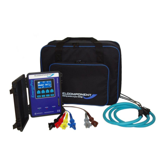
EnergyPro EP600 User Manual
EnergyPro EP600i User's Guide
Copyright © 2010 ELCOMPONENT INSTRUMENTS.
All Rights Reserved.
The information in this document is subject to change without notice.
ELCOMPONENT has made every effort to ensure the accuracy of this manual. However,
ELCOMPONENT makes no warranties with respect to this documentation and disclaims any implied
warranties of merchantability and fitness for a particular purpose. ELCOMPONENT assumes no
responsibility for any errors that may appear in this document.
Trademarks
All product names are copyright and may be trademarks and/or registered trademarks of their
respective companies.
Elcomponent Ltd
Unit 5 Southmill Trading Centre
Southmill Road
Bishop's Stortford
Herts
CM23 3DY
Document number: CID1003.10
Date: 20 April 2011
Advertisement
Table of Contents

Related Manuals for Elcomponent EnergyPro EP600


Summary of Contents for Elcomponent EnergyPro EP600
- Page 1 All Rights Reserved. The information in this document is subject to change without notice. ELCOMPONENT has made every effort to ensure the accuracy of this manual. However, ELCOMPONENT makes no warranties with respect to this documentation and disclaims any implied warranties of merchantability and fitness for a particular purpose.
-
Page 2: Table Of Contents
EnergyPro EP600 User Manual Table of Contents Introduction Safety Firmware Feature Connection Check RMS Data Storage Power Calculations Frequency Energy Usage Display Logger Connection Green Charging LED indicator Red Logging LED indicator Green Charged LED indicator Logger Operation Main Screen Turning On &... -
Page 3: Introduction
EnergyPro EP600 User Manual Introduction The EnergyPro represents leading edge technology in operator interfaces. Data can be viewed in real time on the front panel, or for more detail, PowerView software can be used to examine data collected by the EnergyPro. -
Page 4: Safety
EnergyPro EP600 User Manual Safety Although this instrument is designed to be as safe as possible, safety is ultimately the responsibility of the operator. This instrument should only be operated by suitably qualified and authorized personnel. Please read and UNDERSTAND the following information before operating this instrument ▪... -
Page 5: Firmware Feature
EnergyPro EP600 User Manual Firmware Features Connection Check Before a survey is started the user can set the voltage and current connections from the hook-up screen (press the button). See the Hook-Up Configuration section of this manual for more details. -
Page 6: Logger Connection
EnergyPro EP600 User Manual Logger Connection Connection panel The voltage and current connections are colour coded according to individual phases. Either clamp CT’s or Flex CT may be used to monitor current. The EnergyPro is powered from the voltage between V1 and V2 (between 115V and 600 Vac). If a single phase voltage is being measured then V2 should be connected to neutral in order to receive power from the measured voltage. -
Page 7: Logger Operation
EnergyPro EP600 User Manual Logger Operation Main Screen The main screen of the EnergyPro is a collection of icons that provide access to various configuration setup screens. It also displays general status of the logger such as battery charge state, available memory, and logging status. -
Page 8: Turning On & Off
EnergyPro EP600 User Manual The main screen displays the CT range and storage rate beside their respective icons. Once a change is made, the value beside the icon will be updated automatically. For changes in storage rate, the maximum survey duration display under the memory status bar will also be updated automatically. -
Page 9: Clock Setup
EnergyPro EP600 User Manual Clock Setup The clock setup screen will appear when the clock icon on the main screen has been selected. The scroll key (F4) is used to scroll through the fields: year, month, day, hour, minute or second. The + and - signs (F1 and F2) are used to increase or decrease the value. -
Page 10: Voltage/ Current/ Power Factor Display
EnergyPro EP600 User Manual Voltage / Current / Power Factor Display The voltage/current/power factor screen will appear after pressing the button. It displays RMS voltage, RMS current, and power factor for each phase. Switch between Line-to-Neutral voltage (V and Line-to-Line voltage (V ) by pressing F4. - Page 11 EnergyPro EP600 User Manual The KWHR key (F3) selects the total energy consumption screen. The total energy consumption screen is zeroed at the start of each survey. The maximum KWHRs that can be accumulated is 9,999,999 KWHR. Hook-up Configurations The hook-up screen will appear when the button is pressed.
-
Page 12: 1P2W
EnergyPro EP600 User Manual 1P2W This is for a single phase circuit. The EnergyPro assumes that V1 and CT1 (and CT2, CT3 if used) are connected to the same phase. The 1P2W mode allows the use of CT2 and CT3 for monitoring multiple single phase loads. -
Page 13: Start & Stop Logging
EnergyPro EP600 User Manual Start and Stop logging Before logging, make sure that all connections from the voltage leads and current clamps are secured to the EnergyPro. Remember to insert a memory card and make sure all configurations are set properly. - Page 14 EnergyPro EP600 User Manual Specifications Measurement Specifications Comment V1, V2, V3 0.5 % of full scale 0 - 600 VAC I1, I2, I3 0 - 1V (Clamp) 0.5% of full scale CT’s are voltage output 0 - 100mV (Flex) Sampling...
Need help?
Do you have a question about the EnergyPro EP600 and is the answer not in the manual?
Questions and answers