Table of Contents
Advertisement
Quick Links
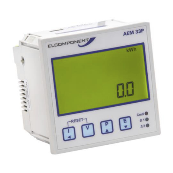
AEM33 P 485 User Manual
Safety
This instrument is manufactured in compliance with EN61010-1 cat. III for nominal operating
voltages of 400V L-L and 230V L-N. To ensure safe operation the user must comply with the
following instructions:
Ensure that the supply voltage is correct.
The auxiliary mains supply is internally fused at 250V, 100mA Type 2. External fusing is required
if the auxiliary supply voltage exceeds 250V.
Maintenance and/or repairs must be carried out only by qualified, authorised personnel.
If there is ever the suspicion that safe use is no longer possible, the instrument must be
disconnected and precautions must be taken against accidental use.
Operation is no longer safe:
1)
If there is clearly visible damage
2)
If the instrument no longer functions
3)
After prolonged storage in unsuitable conditions.
Operator safety
Read these instructions carefully before installing and utilising the instrument.
The instrument described in this user manual is intended for use by properly trained staff only.
Maintenance and/or repairs must be carried out by authorised personnel only. For proper, safe use
of the instrument and for maintenance and/or repair, it is essential that the persons instructed to
carry out these procedures follow normal safety precautions.
Symbols
CAUTION: Failure to follow the instructions may result in personal injury or damage to
equipment.
NOTE: Failure to follow the instructions may result in an instrument malfunction.
Advertisement
Table of Contents

Summary of Contents for Elcomponent AEM33
- Page 1 AEM33 P 485 User Manual Safety This instrument is manufactured in compliance with EN61010-1 cat. III for nominal operating voltages of 400V L-L and 230V L-N. To ensure safe operation the user must comply with the following instructions: Ensure that the supply voltage is correct.
- Page 2 AEM33 P 485 User Manual Connection of the current input The AEM33 is suitable for use with current transformers (CTs) with 5A secondary output. Metering quality CTs of Class 1 accuracy with a minimum rating of 2.5VA are recommended. Connections should be made according to the diagrams below.
-
Page 3: Instrument Operation
AEM33 P 485 User Manual Pulse output connections CAUTION: The pulse output contacts are rated at 100mA AC/DC, 100V max. Under no circumstances should this rating be exceeded. The AEM33P is fitted with a single pulse output proportional to kWh. The output has a telltale LED on the front panel which flashes ‘on’... - Page 4 AEM33 P 485 User Manual VOLTAGE DISPLAY CURRENT DISPLAYS Press to select from the following displays: Press to select from the following displays:...
- Page 5 AEM33 P 485 User Manual POWER DISPLAYS Press to select from the following displays: System Power – Reactive, Apparent Active Voltages 1-3 NOTE: The symbol following the VAr value = capacitive load. A negative indicator before the VAr value indicates exported reactive power.
- Page 6 AEM33 P 485 User Manual Phase PF NOTE: The symbol following the Cos value = capacitive load. System Average Demand Rolling average of user defined MD period System Max Demand Maximum recorded average demand value Instrument set-up To enter programming mode press simultaneously for 5 seconds.
- Page 7 AEM33 P 485 User Manual VT SET-UP The default voltage setting is 400V and this value should not be altered unless the meter is an HV type and is connected via voltage transformer(s). In this instance the nominal line to line voltage of...
-
Page 8: Technical Characteristics
AEM33 P 485 User Manual RS485 SET-UP This allows the baud rate and MODBUS address to be set. Use the and buttons to set the desired baud rate. Press the key to store the value and advance the page.


Need help?
Do you have a question about the AEM33 and is the answer not in the manual?
Questions and answers