Kanardia EMSIS Installation And User Manual
Hide thumbs
Also See for EMSIS:
- User and installation manual (31 pages) ,
- Installation and user manual (64 pages)

Related Manuals for Kanardia EMSIS


Summary of Contents for Kanardia EMSIS
- Page 1 EMSIS Installation and User Manual © Kanardia d.o.o. November 2021 Manual Revision 3.1...
- Page 3 //creativecommons.org/licenses/by-sa/3.0/. In short, the li- cense gives you right to copy, reproduce and modify this document ˆ you cite Kanardia d.o.o. as the author of the original work, ˆ you distribute the resulting work only under the same or similar license to this one.
- Page 4 Emsis — Manual of figures were drawn using Libre Office Draw, Inkscape and Bric- scad applications. Photos and scanned material was processed using Gimp. Sam2p was used to convert pictures into eps format. All document sources are freely available on request under the license mentioned above and can be obtained by email.
- Page 5 Emsis — Manual © Kanardia 2021...
-
Page 6: Table Of Contents
2.2 Turning ON/OFF ....2.3 Updating Emsis Software .... - Page 7 Settings ..... 5.4 Emsis Setup Screen ....
- Page 8 Emsis — Manual CONTENTS 7 Tank 7.1 Software Tank ..... . 7.2 Hardware Tank .....
-
Page 9: Introduction
The Emsis system is a set of complex electronics devices and we strongly recommend to carefully read this manual before installing and using the system. Emsis is a name for a line of flight instruments which can be used as: primary flight display (PFD), engine monitoring system (EMS). -
Page 10: Command Panel
Emsis — Manual 2.1 Command Panel Command Panel Emsis instruments come in two physical sizes. The first one is a standard aviation size, which is 80 mm diagonal, while the second one is non-standard and is characterized with a 3.5” screen diagonal. -
Page 11: Turning On/Off
The power ON/OFF button is normally not used. However on some Emsis instruments, it is used to turn the instrument on/off. Note that 3.5” screen Emsis does not have the power ON/OFF button. The close button serves as the close or cancel command. -
Page 12: Downloading Software
2.3.2 Copying New Software to Emsis To copy the software from the SD card to Emsis follow these steps: 1. Insert SD card with the new software (Update.kus) into Emsis SD card slot. The contacts on the card must face upward. -
Page 13: Firmware Update
file integrity is verified and in the second step the file is copied into Emsis. 4. Once finished, Emsis will start with the new software. The very first start after the update takes slightly longer. The Start normally option is used if you changed your mind and... -
Page 14: Installing New Layout
file. Layouts are prepared by Kanardia and sent to users when requested. Follow the steps below in order to copy a new layout to Emsis. 1. A layout file is usually sent by e-mail to the user. Copy the file to the micro SD card. -
Page 15: Technical Specifications
Emsis — Manual 2.5 Technical Specifications 7. Close all windows. Emsis will reboot with the new layout ac- tive. Technical Specifications Tables 1 and 2 illustrate some general instrument specifications for each instrument size. CAN Bus The Emsis system can be easily extended into a much more complex form, shown in Figure 3. - Page 16 590 hPa to 1080 hPa (17.42 to 31.89 inHg) Communication CAN bus, 29 bit header, 500 kbit, Kanardia protocol Display 240 x 320 pix, 2.7”, 24 bit, full colour, super bright Table 1: Basic technical specifications for the 80 mm Emsis. © Kanardia 2021...
- Page 17 590 to 1080 hPa (17.42 to 31.89 inHg) Communication CAN bus, 29 bit header, 500 kbit, Kanardia protocol Display 240 x 320 pix, 3.5”, 24 bit, full colour, super bright Table 2: Basic technical specifications for the 3.5” Emsis. © Kanardia 2021...
-
Page 18: Emsis Pfd
AHRS provides attitude, position and velocities. AHRS unit is hidden inside Emsis PFD unit. ˆ Emsis unit – presents all relevant information that appears on the CAN bus in a pilot friendly form on LCD screen. Most of this manual describes how to access, read and interact with the Emsis display. -
Page 19: Emsis Ems
GPS position. Again, Kalman filtering is used to obtain the final solution. When engine monitoring unit (Daqu) is present on CAN bus, Emsis PFD can also show relevant engine and fuel information. When maps are enabled and licensed, Emsis PFD can also show raster maps on graphical display. -
Page 20: Engine Sensors
Emsis display. Figure 4: Illustration of Emsis EMS configuration When AHRS unit is present on CAN bus, Emsis EMS can also show flight information on graphical display, too. When maps are enabled and licensed and AHRS unit is present on CAN bus, Emsis EMS can also show raster maps on graphical display. -
Page 21: Screens
More about Daqu unit and engine sensors is written in Daqu Instal- lation Manual. Screens The Emsis unit can toggle between several main screens depending on your Emsis type: ˆ Primary flight display (PFD) screen – artificial horizon with air data. - Page 22 Figure 5. It will take the current pitch and set it as zero pitch. The change is not immediate and it takes ca. 5 seconds for AHRS unit to accept it. Once Emsis is switched off, this setting is forgotten.
-
Page 23: Primary Flight Display Screen
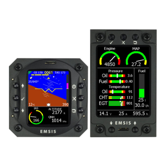
The Primary flight display (PFD) screen is illustrated in Figure 6. It displays artificial horizon with flight data information. Figure 6: Emsis primary flight display screen PFD screen consists of the following items: Quality of the GPS fix. Three green bars mean 3D fix, two yellow bars are 2D fix and cross means no signal from GPS. -
Page 24: Engine Monitoring Screen
(12 degrees per second). Engine Monitoring Screen An example of engine monitoring screen is illustrated in Figure 7. It can be designed differently for each Emsis unit regarding to the wishes of the customer. Additionally, more than one EMS screen can be configured. - Page 25 Emsis — Manual 5.2 Engine Monitoring Screen Figure 7: Emsis engine monitoring screen Fuel level with the numeric indication. Fuel consumption (fuel flow). Engine total time. Ampere meter (electrical current meter). System voltage. Water temperature. CHT with two sensors and the largest value of both.
- Page 26 Emsis — Manual 5.2 Engine Monitoring Screen This is just a subset of options. Emsis can also display: rotor RPM, pneumatic pressure, trim positions, gearbox temperature, carburetor temperature and much more. Additionally, the engine parameters can be mixed with flight parameters. So, you can see the altitude, airspeed, QNH, etc.
-
Page 27: Maps Screen
Maps Screen The Maps screen is illustrated in Figure 9. Maps can be shown on Emsis only if GPS information is present on the CAN bus. Emsis PFD supports this by default, while other versions depend on units that are connected to the CAN bus (Nesis, some other Emsis PFD, Horis, etc.). -
Page 28: Zoom Level
5.3.3 Copying In order to copy a new map to Emsis, you need to obtain this map from our web site. Copy this map to the micro SD card that you ©... -
Page 29: Deleting
Once you have a map on the micro SD card, do the following: ˆ Insert the SD card into Emsis with the contacts facing up. ˆ Select the Setup screen, Maps Copy Maps option. ˆ If asked, enter standard password 314. -
Page 30: Information
Figure 10: Copying maps (left) and maps info window (right) 5.3.5 Information In order to see which maps are loaded into Emsis internal memory, select the Setup screen, Maps Maps Info option. A list of maps appears. If you have a lot of maps loaded, there may be a delay. -
Page 31: Emsis Setup Screen
5.4 Emsis Setup Screen Emsis Setup Screen The Emsis Setup screen allows you to access or set several options. It is accessed by pushing the screen selector button. Figure 11 illustrates the screen. The displayed options depend on the hardware detected on the CAN bus. - Page 32 Figure 12: Emsis password is required in order to access certain op- tions The factory password is 314, first three most significant digits of number as seen in Figure 12.
-
Page 33: Logbook
Emsis — Manual 5.4 Emsis Setup Screen 5.4.1 Logbook The logbook window allows you to get some information about your flights. The logbook view differs between PFD and EMS mode. PFD Mode The logbook window lists recent flights in reverse or- der (last flight is listed first). -
Page 34: Engine
Engine Type Depending on specifications of your aircraft, select the correct engine. Figure 13 shows the engine selection window. Setting the engine type allows Emsis to calculate fuel consumption and has no other effect on the instrument. Figure 13: Engine type selection window Available engines are: ˆ... - Page 35 Emsis — Manual 5.4 Emsis Setup Screen ˆ Rotax 582 65 – two stroke 65 HP Rotax engine. ˆ Jabiru 2200 – four cylinder Jabiru engine. ˆ Jabiru 3300 – six cylinder Jabiru engine. ˆ Geiger Wankel ˆ MW Fly + CC-m ˆ...
- Page 36 Emsis — Manual 5.4 Emsis Setup Screen Figure 14: List of sensors connected to Daqu unit Each row in the table corresponds to one Daqu channel. Channels are labelled as combination of one capital letter and one number. Letters define the channel type, while numbers enumerate channels of each type.
- Page 37 Emsis — Manual 5.4 Emsis Setup Screen ˆ D: Same as B, but it also allow you to connect sensors that generate 4-20 mA current loop (one typical sensor is Rotax oil pressure sensor). ˆ E: Same as B, but it also allows measuring resistance with stronger current generator.
-
Page 38: Min/Max Values
5.4.3 Min/Max Values Certain sensors require min/max values (trim sensors, position indi- cation sensors, flap sensors). In this case you have to tell Emsis the sensor reading at minimum position and the reading at maximum position. Figure 16: Position sensor min/max window In order to show the Min/Max dialog on the screen, select the channel ©... -
Page 39: Tank
Brightness The brightness option is visible only when default action for up & down buttons is set to QNH. This is typical for Emsis PFD. Select the option and use up & down buttons to adjust the brightness. Note that Emsis always starts with maximal brightness. - Page 40 Emsis — Manual 5.4 Emsis Setup Screen Figure 17: Airspeed configuration window 4. Yellow 2 – to this limit the range is yellow. The second yellow range is the range, in which the aircraft may be operated in smooth air, and then only with caution to avoid abrupt control movement.
-
Page 41: Units
Table 3 shows available units. 5.4.8 Pilots The Emsis PFD version allows you to enter several pilots who typi- cally fly the aircraft. You can create a new pilot, edit an existing one or remove one. -
Page 42: Maps
Emsis — Manual 5.4 Emsis Setup Screen Physical quantity Available units Latitude/Longitude format D MM’ SS”, D MM.MM Directions True, Magnetic UTC Difference Difference between local time and UTC Distance (length) nm, sm, km Speed (velocity) km h, kts, mph... - Page 43 ˆ Import layout - This option lists all layouts available on the SD card. By selecting a layout, it will be copied from the SD to Emsis. To activate this layout, select it in the Layout menu option. ˆ Import alarms - This option lists all alarms available on the SD card.
- Page 44 Emsis — Manual 5.4 Emsis Setup Screen ˆ Firmware update - Used to update the software in Daqu, Airu, Magu. ˆ RamBoot update - Used to update the initial boot software. ˆ Logger settings - Used to define some logger settings.
- Page 45 Please make sure that airplane is level for both, roll and pitch. Make also sure that Emsis unit is turned ON for at least five minutes – this warms up the internal electronics and stabilizes numerical filters. Once the airplane is level and steady, select the AHRS level option to start the automatic calibration procedure.
- Page 46 Emsis — Manual 5.4 Emsis Setup Screen Wait for the progress bar to finish and observe the roll and pitch numerical values. At the end they should be close to zero. Close the window. This also stores new values. Compass Calibration This option is available only when Magu (electronic magnetic compass) is also present on the CAN bus.
- Page 47 Emsis — Manual 5.4 Emsis Setup Screen full. You have to make more than a full circle because the initial readings are not used in computation. At this point a blue ellipse is drawn on the chart. Corrections up to 15 degrees are generally accepted as appropriate.
- Page 48 Emsis — Manual 5.4 Emsis Setup Screen Firmware Update This command updates the software of devices present on the CAN bus: AD-AHRS module (Airu), EMS module (Daqu), compass module (Magu), etc. Do not use this function unless we advise you to do so.
- Page 49 Emsis — Manual 5.4 Emsis Setup Screen ˆ Rotor RPM threshold shall be defined for helicopters and gyro- planes only. In order to detect the landing situation, the logger monitors two things: IAS and rotor RPMs. They both must be below the specified thresholds in order to detect the landing.
-
Page 50: About
If fuel flow sensor is installed this factor has no effect. Figure 27: Fuel flow factor window 5.4.11 About The About window shows some relevant information about Emsis: ˆ selected layout ˆ program version, © Kanardia 2021... -
Page 51: Installation
ˆ outside air temperature (OAT) sensor installation. Installation to the Instrument Panel This section covers the installation of the Emsis unit. Emsis 80 mm version is presented (standard avionics unit dimension), while the same principles apply for the Emsis 3.5” screen version. -
Page 52: Emsis Back Panel Connectors And Cable Clearance
Emsis Back Panel Connectors and Cable Clearance Emsis units are divided into two main groups (according to the back panel), Emsis with AHRS unit built-in and all the others. Here is a brief description of individual connectors from Figure 28: Figure 28: Emsis unit with AHRS built-in (left), Emsis slave unit (right). - Page 53 Emsis 3.5” screen version requires similar clearance space. Emsis PFD is shipped with a connector inserted into one CAN port. It is a 120 Ω network terminator resistor to start and terminate the network. When Daqu unit is connected, terminator can be disconnected.
-
Page 54: Connection To The Electrical System
Figure 29: Side photo of Emsis 80mm version with all cables con- nected Connection to the Electrical System The Emsis unit must be connected to a 12 V DC standard aircraft power source. Additionally it can be connected to the backup battery – UPSU unit. -
Page 55: Pitot-Static Connection
When you use more than one Emsis unit in the cockpit, other Emsis units get power via CAN cable. On our website you will find connection schema for Emsis unit with or without UPSU unit. -
Page 56: Outside Air Temperature Probe Installation
Emsis — Manual 6.4 Outside Air Temperature Probe Installation Outside Air Temperature Probe Installation Although the OAT probe is a simple element in the Emsis PFD system, its installation requires some attention. Outside air temperature (OAT) probe is shipped with the Emsis PFD unit. -
Page 57: Connection To The Can Network
In standard configurations with Emsis PFD, one CAN port is con- nected to terminator, while the other is unused or connected to other Emsis unit. One CAN port may be used to connect with Daqu (en- gine monitoring unit), in this case terminator can be disconnected. -
Page 58: Connection To The 485 Network
Emsis — Manual 6.6 Connection to the 485 Network Connection to the 485 Network The RS-485 connector is obsolete. It was used to connect devices via 485 protocol. It will be replaced by RS-232 connector in forthcoming versions. GPS Antenna Installation... -
Page 59: Tank
Software Tank The software tank is active when no fuel level channel is configured in Daqu. Emsis allows you to enter the current amount of fuel and this amount is then reduced in time based on fuel consumption. The fuel consumption is either calculated or measured. Measured fuel consumption usually gives better results assuming that a high quality fuel flow sensor is applied. -
Page 60: Hardware Tank
Emsis — Manual 7.2 Hardware Tank Figure 31: Software (simulated) fuel tank level adjustment Hardware Tank Hardware tank is based on fuel level sensors. First you need to con- nect sensors to Daqu and activate/configure appropriate channels. Once this is completed, you can continue with tank calibration. -
Page 61: Units
Fuel level volume value on the CAN bus is always represented in liters. Hence the complete tank calibration process must be done in liters. Emsis will ignore the volume unit setting and always consider the numbers you are entering as liters. -
Page 62: Tank Calibration In Steps
Emsis — Manual 7.2 Hardware Tank (a) Channel E01 set for a tank (b) Channel E02 set for a tank with with a resistive fuel level sen- an active sensor (e.g. a capaci- sor for a measuring range be- tive sensor) with voltage output tween 0 and 400 Ω. - Page 63 Emsis — Manual 7.2 Hardware Tank 4. Make sure the tank is empty and make sure the aircraft is level as it will be in the flight. 5. Select T1 Shape from the Tank option in order to open the tank calibration window.
- Page 64 Emsis — Manual 7.2 Hardware Tank 9. Add the first point, which represents empty tank situation. Press the OK and select Add. Change volume to 0 and press close button. This will add the first point. Sensor value is recorded automatically. Write this point down (volume and sensor pair) to the notebook.
- Page 65 Emsis — Manual 7.2 Hardware Tank its max point) way before the tank is completely full. Stop at the point where sensor do not react anymore. 13. Close the Edit tank window pressing the close button. Now you are back to the Tank window. This window shows your tank curve.
-
Page 66: Tank Calibration Using Known Shape
7.2.4 Tank Calibration Using Known Shape Emsis has several build in tank shapes and new ones are being added into new versions all the time. If your tank matches one of them, you can use it and save some time. In theory, this approach is as good as the previous one. - Page 67 Emsis — Manual 7.2 Hardware Tank position differences. It gives good results, when sensor behaviour is predictable (read relay based sensors, for example) or in serial production, when sensor are installed with high precision. This procedure requires two steps. In the first step, the tank shape is selected and in the second step, sensor value for empty (min) and full (max) condition is given.
- Page 68 Emsis — Manual 7.2 Hardware Tank 3. Once the correct shape is selected, press close to save the selection. 4. Select the Tank:T1 min/max from the menu. Figure 37 shows an example. Figure 37: Window for setting the tank minimum and maximum val- ues.
-
Page 69: Limited Conditions
(24) months from retail purchase. Warranty Coverage Kanardia’s warranty obligations are limited to the terms set forth below: Kanardia d.o.o. warrants the Kanardia-branded hardware product will conform to the published specification when under normal use for a period of twenty-four months (24) from the date of retail pur- chase by the original end-user purchaser (”Warranty Period”). - Page 70 Kanardia; (f) to consumable parts, such as batteries, unless damage has occurred due to a defect in materials or workmanship; or (g) if any Kanardia serial number has been removed, altered or defaced.
- Page 71 Kanardia products and any failure to maintain the confidentiality of data stored on the product. Under no circumstances will Kanardia be liable for the provision of substitute goods or services.
-
Page 72: 8.2 Tso Information
This product is not TSO approved as a flight instrument. Therefore, the manufacturer will not be held responsible for any damage caused by its use. The Kanardia is not responsible for any possible damage or destruction of any part on the airplane caused by default operation of instrument.
Need help?
Do you have a question about the EMSIS and is the answer not in the manual?
Questions and answers