Kanardia EMSIS Installation And User Manual
Hide thumbs
Also See for EMSIS:
- User and installation manual (31 pages) ,
- Installation and user manual (72 pages)
Table of Contents
Advertisement
Quick Links
Advertisement
Table of Contents

Related Manuals for Kanardia EMSIS


Summary of Contents for Kanardia EMSIS
- Page 1 EMSIS Installation and User Manual © Kanardia d.o.o. February 2023 Revision 3.2...
- Page 3 3.0/. In short, the license gives you right to copy, reproduce and modify this document if: • you cite Kanardia d.o.o. as the author of the original work, • you distribute the resulting work only under the same or similar license to this one.
- Page 4 Emsis — Manual Rev. Date Description Feb 2023 Rotax iS section, parameters editing, adjusted to SW 3.11. Nov 2021 Figures and text updated to the latest version. May 2020 Latex rewrite. 2.13 July 2016 Bug fixes, red crosses on interactive parameters, heading indicator, Lo-Hi-NC messages.
-
Page 5: Table Of Contents
2.2 Turning ON/OFF ......10 2.3 Updating Emsis Software ..... 10 2.3.1... - Page 6 Caution Message ..... . 28 5.5 Emsis Setup Screen ......29 6 Setup Options 6.1 Logbook .
- Page 7 8.1 Installation to the Instrument Panel ....47 8.1.1 Emsis Back Panel Connectors and Cable Clearance . . . 48 8.2 Connection to the Electrical System ....49 8.3 Pitot-Static Connection .
-
Page 8: Introduction
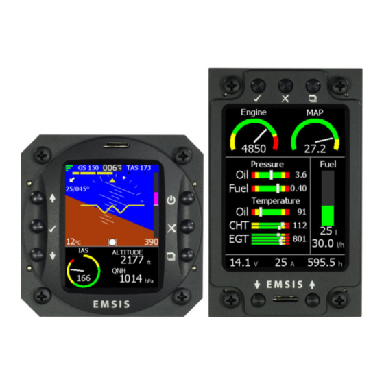
1. Introduction Introduction First of all, we would like to thank you for purchasing our product. The Emsis system is a set of complex electronics devices and we strongly recommend to carefully read this manual before installing and using the system. - Page 9 Emsis — Manual 2.1 Command Panel Figure 1: Organization of Emsis front panel. Emsis 80 mm version (left), Emsis 3.5” screen version (right) ○ The up arrow button is used to move the menu selection, to change a value or a letter within active control or some other screen-specific function.
-
Page 10: Turning On/Off
Once the file was copied, please make sure to use safely remove option on the PC, before you remove the card from PC. Emsis software versions 2.4 and earlier support only micro SD cards with the capacity of 2GB or less. Later versions also recognise HDSD cards with a higher capacity (up to 32 GB). -
Page 11: Copying New Software To Emsis
1. Insert SD card with the new software (Update.kus) into Emsis SD card slot. The contacts on the card must face upward. 2. On Emsis 80, push and hold the down arrow (on Emsis 3.5”, push and hold the up arrow) and turn Emsis ON. A window similar to Figure 2 appears. -
Page 12: Installing New Layout
Layouts are prepared by Ka- nardia and sent to users when requested. Follow the steps below in order to copy a new layout to Emsis. 1. A layout file is usually sent by e-mail to the user. Copy the file to the micro SD card. -
Page 13: The Can Bus
Table 1: Basic technical specifications for the 80 mm Emsis. The CAN Bus The Emsis system can be easily extended into a much more complex form, shown in Figure 3. We achieved this by introducing CAN bus for the commu- nication between the units. - Page 14 Table 2: Basic technical specifications for the 3.5” Emsis. can be easily connected to the network, we connect all new devices to CAN. This allows introduction of secondary Emsis unit, electronic compass (Magu), pilot command stick, etc. © Kanardia 2021...
-
Page 15: Emsis Pfd
AHRS provides attitude, position and velocities. AHRS unit is hidden inside Emsis PFD unit. • Emsis unit – presents all relevant information that appears on the CAN bus in a pilot friendly form on LCD screen. Most of this manual de- scribes how to access, read and interact with the Emsis display. -
Page 16: Emsis Ems
CAN bus in a pilot friendly form on LCD screen. Most of this manual describes how to access, read and interact with the Emsis display. When AHRS unit is present on CAN bus, Emsis EMS can also show flight information on graphical display, too. -
Page 17: Engine Sensors
Emsis — Manual 4.1 Engine Sensors Figure 4: Illustration of Emsis EMS configuration Engine Sensors Engine related sensors are connected to the engine monitoring unit Daqu. Daqu is designed to be installed on the engine side of the firewall. This has two advantages: •... -
Page 18: Screens
Figure 5. It will take the current pitch and set it as zero pitch. The change is not immediate and it takes ca. 5 seconds for AHRS unit to accept it. Once Emsis is switched off, this setting is forgotten. -
Page 19: Primary Flight Display Screen
Primary Flight Display Screen The Primary flight display (PFD) screen is illustrated in Figure 6. It displays artificial horizon with flight data information. Figure 6: Emsis primary flight display screen PFD screen consists of the following items: ○ Quality of the GPS fix. Three green bars mean 3D fix, two yellow bars are 2D fix and cross means no signal from GPS. -
Page 20: Engine Monitoring Screen
Engine Monitoring Screen An example of engine monitoring screen is illustrated in Figure 7. It can be designed differently for each Emsis unit regarding to the wishes of the customer. Additionally, more than one EMS screen can be configured. EMS screen from Figure 7 shows the following items: ○... - Page 21 Fuel pressure. ○ Oil pressure. This is just a subset of options. Emsis can also display: rotor RPM, pneumatic pressure, trim positions, gearbox temperature, carburetor temperature and much more. Additionally, the engine parameters can be mixed with flight parameters. So, you can see the altitude, airspeed, QNH, etc. as well.
- Page 22 Emsis — Manual 5.2 Engine Monitoring Screen Figure 8: Examples of Emsis engine monitoring screens • If you see red cross over some parameter, it means that this parameter does not receive data from the CAN bus. This usually means that parameter is not configured properly.
-
Page 23: Maps Screen
5.3 Maps Screen Maps Screen The Maps screen is illustrated in Figure 9. Maps can be shown on Emsis only if GPS information is present on the CAN bus. Emsis PFD supports this by default, while other versions depend on units that are connected to the CAN bus (Nesis, some other Emsis PFD, Horis, etc.). -
Page 24: Zoom Level
5.3.3 Copying In order to copy a new map to Emsis, you need to obtain this map from our web site. Copy this map to the micro SD card that you received with the instrument. (You may use other micro SD cards as well.) Do not put the maps into any folders. -
Page 25: Deleting
• A list of the maps on the SD card appears. Select a map you want to copy and press the OK button. • Copy procedure commences. Copying is very slow in Emsis. A large file may take a few hours to copy. Please make sure the batteries are full before you begin. -
Page 26: Information
5.4 Rotax iS Status Screen 5.3.5 Information In order to see which maps are loaded into Emsis internal memory, select the Setup screen, Maps Maps Info option. A list of maps appears. If you have a lot of maps loaded, there may be a delay. -
Page 27: Eco Label
Emsis — Manual 5.4 Rotax iS Status Screen (a) A typical situation. (b) An error situation. Figure 11: Rotax iS status screen examples. Yellow equals to the lane control lamp flushing on and off. The lane is signaling some warning condition. -
Page 28: Sensor Status
Emsis — Manual 5.4 Rotax iS Status Screen An engine status summary is shown as a text below the lane line. This gives some instruction what to do if some error is detected. According to the Rotax Operators Manual for 912 iS and 915 iS engines, section 4.1 EMS Warning Lamps, the following advice is given: All is normal both lanes are green –... -
Page 29: Emsis Setup Screen
6. Figure 13 illustrates the screen. The displayed options depend on the hardware detected on the CAN bus. Thus, Emsis EMS version does not show the same options as Emsis PFD version. -
Page 30: Setup Options
Service is a gateway to the service specific settings. About displays information about software and hardware version. Some user options are not shown on secondary Emsis, some options require password entry before proceeding and some options are available only when correct hardware is detected. -
Page 31: Ems Mode
Engine Type Depending on specifications of your aircraft, select the correct engine. Figure 15 shows the engine selection window. Setting the engine type allows Emsis to use some fuel consumption model and to activate correct mode in miniDaqu or modified standard Daqu in the case of ECU equipped engines. -
Page 32: Switch Function
Emsis — Manual 6.2 Engine 6.2.2 Switch Function Switch function settings are used when configuring miniDaqu unit. Read more about this option in our MiniDaqu Manual. 6.2.3 Sensors The sensor menu is used to configure channels on Daqu. For each channel we define its function, sensor type and some specific parameters. - Page 33 Emsis — Manual 6.2 Engine • A: analog channels with –2.5 V to +2.5 V input, which are typically used to connect resistive sensors and thermocouples. • B: analog channels with 0 to +5 V input, used to read active sensors.
-
Page 34: Min/Max Values
Min/Max Values Certain sensors require min/max values (trim sensors, position indication sen- sors, flap sensors). In this case you have to tell Emsis the sensor reading at minimum position and the reading at maximum position. In order to show the Min/Max dialog on the screen, select the channel and press and hold the OK button (long press). -
Page 35: Brightness
The brightness option is visible only when default action for up & down buttons is set to QNH. This is typical for Emsis PFD. Select the option and use up & down buttons to adjust the brightness. Note that Emsis always starts with maximal brightness. -
Page 36: Filter
Please note that some engine parameters are already filtered by Daqu and you may want to address the response behavior there first. The larger number wins. So, if a large filter is set in Daqu and small value in Emsis, Daqu wins. 6.5.2 Index Count This options is available to CHT and EGT parameters only. - Page 37 Emsis — Manual 6.5 Parameters that the bar starts at 20 C. Next there is a green part until 110 C, followed by the yellow part until 120 C and the bar ends with red part at 130 C. By changing the Start with value, the start of color band is define. All values below this will translate to an empty bar.
-
Page 38: Units
Units configuration is accessible by selecting the Units option from the Setup screen. A window illustrated in Figure 22 opens. Figure 22: List of configurable units in Emsis unit Emsis uses several units for different physical quantities like distance, velocity, mass, volume, etc. Table 3 shows available units. Physical quantity... -
Page 39: Pilots
6.7 Pilots Pilots The Emsis PFD version allows you to enter several pilots who typically fly the aircraft. You can create a new pilot, edit an existing one or remove one. Each pilot has a name and optional instructor rating. A pilot, who is also an instructor can have two roles. -
Page 40: Service
Emsis — Manual 7. Service Figure 24: An example of the About window. • Selected layout name. • Emsis program version, • Emsis boot-loader version, • Serial number and hardware version, • Total Hobbs time (power on time), • Total flight time, •... - Page 41 Emsis — Manual 7. Service The service window is accessed from the Emsis Setup page by selecting the Service item and entering the 314 password, see Figure 23. Layout allows you to select current layout from all layouts loaded into Emsis.
-
Page 42: Layout
Please make sure that airplane is level for both, roll and pitch. Make also sure that Emsis unit is turned ON for at least five minutes – this warms up the internal electronics and stabilizes numerical filters. © Kanardia 2021... -
Page 43: Compass Calibration
Emsis — Manual 7.3 Compass Calibration Once the airplane is level and steady, select the AHRS level option to start the automatic calibration procedure. Window illustrated in Figure 26 opens. Figure 26: Calibrating the AHRS level Wait for the progress bar to finish and observe the roll and pitch numerical values. -
Page 44: Firmware Update
Emsis — Manual 7.5 Firmware Update Figure 27: Calibrating Magu, situation before rotating (left) and after full rotation (right) The procedure mentioned above removes most of the compass error and in most cases this is more than enough. However, some constant error in all direction remains. -
Page 45: Ramboot Update
Emsis — Manual 7.6 Logger Settings 7.5.1 RamBoot Update This command updates the startup software, which takes care for the instru- ment start. Do not use this function unless we advise you to do so. Logger Settings Here we can tune some logger specific parameters. These parameters are used to identify conditions for the take-off, landing and engine start/stop. -
Page 46: Up/Down
Emsis — Manual 7.7 Up/Down Landing rotor RPM threshold shall be defined for helicopters and gyro- copters only. In order to detect the landing situation, the logger mon- itors two things: IAS and rotor RPM. They both must be below the specified thresholds in order to detect the landing. -
Page 47: Installation
• outside air temperature (OAT) sensor installation. Installation to the Instrument Panel This section covers the installation of the Emsis unit. Emsis 80 mm version is presented (standard avionics unit dimension), while the same principles apply for the Emsis 3.5” screen version. -
Page 48: Emsis Back Panel Connectors And Cable Clearance
You can powder paint the panel using non-reflective dark paint. This makes excellent results in practice. The Emsis unit is mounted from the back. Position Emsis unit in the instru- ment panel and use the screws to fix it in place. -
Page 49: Connection To The Electrical System
Additionally it can be connected to the backup battery – UPSU unit. Emsis PFD is shipped with a connector inserted into one CAN port. It is a 120 Ω network terminator resistor to start and terminate the network. When Daqu unit is connected, terminator can be disconnected. -
Page 50: Pitot-Static Connection
Otherwise your aircraft electrical system needs a good inspection. Emsis with AHRS unit built-in is shipped with 1 m power cable with 2 pin female connector on one side and unterminated solid lines on the other. Red line connects to the 12 V DC avionics power bus and blue line connects to the aircraft common ground. -
Page 51: Outside Air Temperature Probe Installation
8.4 Outside Air Temperature Probe Installation Outside Air Temperature Probe Installation Although the OAT probe is a simple element in the Emsis PFD system, its installation requires some attention. Outside air temperature (OAT) probe is shipped with the Emsis PFD unit. -
Page 52: Connection To The Can Network
Connection to the CAN Network Both CAN ports at the back of the Emsis unit are equivalent. In most standard configurations with Emsis EMS, one CAN port is used to connect with Daqu (engine monitoring unit), while the other is unused or connected to other Emsis unit. -
Page 53: Tank
The software tank is active when no fuel level channel is configured in Daqu. Emsis allows you to enter the current amount of fuel and this amount is then reduced in time based on fuel consumption. The fuel consumption is either calculated or measured. -
Page 54: Hardware Tank
When software tank is active, selecting the Tank item from the Emsis Setup screen displays the Set fuel window, figure 35. Use the up and down buttons to adjust the fuel level. -
Page 55: Units
Fuel level volume value on the CAN bus is always represented in liters. Hence the complete tank calibration process must be done in liters. Emsis will ignore the volume unit setting and always consider the numbers you are entering as liters. -
Page 56: Tank Calibration In Steps
Emsis — Manual 9.2 Hardware Tank (a) Channel E01 set for a tank with (b) Channel E02 set for a tank with a resistive fuel level sensor for a an active sensor (e.g. a capacitive measuring range between 0 and sensor) with voltage output in 0-5V 400 Ω. - Page 57 Emsis — Manual 9.2 Hardware Tank 6. Press and hold the OK button – this opens Edit Tank window, Figure 38b. (On older SW versions you had to press and hold the Down button.) (a) A Tank window example. (b) An Edit Tank window example.
- Page 58 Emsis — Manual 9.2 Hardware Tank be as small as 0 or as large as 15 liters (or even more). If sensor has reacted (its value is different from the empty case) and later on the value has stopped changing, write down the total amount of fuel and sensor value to the notebook and then press OK and Add.
-
Page 59: Tank Calibration Using Known Shape
9.2.4 Tank Calibration Using Known Shape Emsis has several build in tank shapes and new ones are being added into new versions all the time. If your tank matches one of them, you can use it and save some time. In theory, this approach is as good as the previous one. - Page 60 Emsis — Manual 9.2 Hardware Tank sensors, for example) or in serial production, when sensor are installed with high precision. This procedure requires two steps. In the first step, the tank shape is selected and in the second step, sensor value for empty (min) and full (max) condition is given.
- Page 61 Emsis — Manual 9.2 Hardware Tank Figure 41: Window for setting the tank minimum and maximum values. Your values will be different. value. The second option is to manually enter some known min and max values from previous calibrations. • Working with fuel: Make sure that the tank of the aircraft is empty and the fuel level sensor is connected to Daqu unit.
-
Page 62: Limited Conditions
(1) or (2) is not possible (as determined by Kanardia in its sole discretion), (3) refund the purchase price of the product. When a refund is given, the product for which the refund is provided must be returned to Kanardia and becomes Kanardia’s property. - Page 63 No Kanardia reseller, agent, or employee is authorized to make any modification, extension, or addition to this warranty, and if any of the foregoing are made, they are void with respect to Kanardia. Limitation of Liability...
-
Page 64: 10.2 Tso Information
Kanardia products and any failure to maintain the confidentiality of data stored on the product. Under no circumstances will Kanardia be liable for the provision of substitute goods or services.
Need help?
Do you have a question about the EMSIS and is the answer not in the manual?
Questions and answers