
Related Manuals for Advantech RR75i v2


Summary of Contents for Advantech RR75i v2
- Page 1 GSM-R Router RR75i v2 USER’S MANUAL LUCOM GmbH — Flößaustr. 22a — 90763 Fürth — Tel.: +49 911/ 957 606 00 — E-Mail: info@lucom.de — www.lucom.de...
- Page 2 Website www.advantech-bb.com c 2020 Advantech Czech s.r.o. No part of this publication may be reproduced or transmitted in any form or by any means, electronic or mechanical, including photography, recording, or any information storage and retrieval system without written consent. Information in this manual is subject to change without notice, and does not represent a commitment on the part of Advantech.
- Page 3 Please see http://ep.advantech-bb.cz/devzone for more information. Advantech Czech s.r.o., Sokolska 71, 562 04 Usti nad Orlici, Czech Republic Document No. MAN-0015-EN, revision from May 19, 2020. Released in the Czech Republic. LUCOM GmbH — Flößaustr. 22a — 90763 Fürth — Tel.: +49 911/ 957 606 00 — E-Mail: info@lucom.de — www.lucom.de...
-
Page 4: Table Of Contents
RR75i v2 Contents 1 Safety Instructions 2 WEEE directive 3 Router description 4 Contents of package 5 Router Design 5.1 Router versions ........ - Page 5 RR75i v2 7.1 Technical parameters of router ......7.2 Technical parameters of module ......
- Page 6 RR75i v2 List of Figures Contents of package ....... . .
- Page 7 RR75i v2 List of Tables Router versions ........
-
Page 8: Safety Instructions
RR75i v2 1. Safety Instructions Please, observe the following instructions: The router must be used in compliance with all applicable international and national laws and in compliance with any special restrictions regulating the utilization of the router in prescribed applications and environments. -
Page 9: Weee Directive
RR75i v2 2. Product Disposal Instructions The WEEE (Waste Electrical and Electronic Equipment: 2012/19/EU) directive was in- troduced to ensure that electrical/electronic products are recycled using the best available recovery techniques in order to minimize impact on the environment. This product contains high quality materials and components which can be recycled. -
Page 10: Router Description
Mobile Communications – Railway) this router is used for secure and highly reliable com- munication in the railway network. Among the main advantages of RR75i v2 router includes high modularity – router offers a number of serial or wireless interfaces for connecting user devices. -
Page 11: Contents Of Package
RR75i v2 4. Contents of package Basic delivered set of router includes: router, power supply, crossover UTP cable, external antenna, clip for the DIN rail, installation CD containing instructions, paper start guide. Figure 1: Contents of package Note: The router box and DIN mount are supplied in a metal case in the SL version. -
Page 12: Router Design
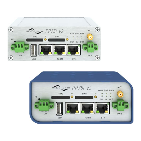
RR75i v2 5. Router Design 5.1 Router versions RR75i v2 router is supplied in the following versions: SIM1 SIM2 PORT1 PORT2 RR75i v2B Plastic RR75i v2B SL Metal RR75i v2F Plastic RR75i v2F SL Metal Table 1: Router versions Figure 2: Front panel RR75i v2B... -
Page 13: Label Examples
RR75i v2 5.2 Delivery identification Trade name Type name Other RR75i v2B RR-75i-v2 Basic version RR75i v2B SL RR-75i-v2 Basic version in the metal box RR75i v2F RR-75i-v2 Full version RR75i v2F SL RR-75i-v2 Full version in the metal box Table 2: Delivery identification... -
Page 14: Type Of Port #1
RR75i v2 5.3 Order codes 5.3.1 Order code structure Order code for full version has following structure: BB-RR2F52v02y , where: v = port #1, y = type of power supply. Letter "v" – port #1 Port type Letter "v" in code... -
Page 15: Basic Dimensions Of Plastic Box
RR75i v2 5.4 Basic dimensions of plastic box Figure 7: Basic dimensions of plastic box 5.5 Basic dimensions of metal box Figure 8: Basic dimensions of metal box LUCOM GmbH — Flößaustr. 22a — 90763 Fürth — Tel.: +49 911/ 957 606 00 — E-Mail: info@lucom.de — www.lucom.de... -
Page 16: Space Around Antennas
RR75i v2 5.6 Mechanical dimensions and mounting recommendations Mounting recommendations: possibility to be put on a work surface, DIN rail with clips CPD2 (ELPAC clip SL for metal version) are included. For the most of applications with a built-in router in a switch board it is possible to recognize... -
Page 17: Cable Routing
RR75i v2 For every cables we recommend to bind the bunch according to the following picture, we recommend for this use: – Length of the bunch (combination of power supply and data cables) can be max- imum 1,5 m. If the length of data cables exceeds 1,5 m or in the event of, the cable leads towards the switch –... -
Page 18: Default Position Of Plastic And Metal Din Rail Clip
RR75i v2 5.7 Removal from the DIN rail The DIN rail clip is suitable for a DIN rail according to EN 60715 standard only. The default position of plastic or metal rail clip, which is used for mounting the router on a DIN rail, is shown in the following figure. -
Page 19: Front Panel Rr75I V2F
RR75i v2 5.8 Description of the front panel On the front panel is located: Caption Connector Description 2-pin Connector for the power supply adapter. RJ45 Connector for connection into the local computer network. PORT1 RJ45 Connector for expansion port RS232, RS458/422, MBUS, ETHERNET, CNT or SWITCH. -
Page 20: Router Status Indication
RR75i v2 5.8.1 Status indication About router status inform eight LED indicators on the front panel and on every port are two LED indicators, which inform about port status. Caption Color State Description Green Blinking Router is ready Starting of the router Fast blinking Updating firmware... -
Page 21: Power Connector
RR75i v2 5.8.2 Power connector PWR Panel socket 2-pin. Pin number Signal mark Description VCC(+) Positive pole of DC supply voltage (+10 to +30 V DC) GND(-) Negative pole of DC supply voltage Table 8: Connection of power connector Figure 19: Power connector Power supply for router is required between +10 V to +30 V DC supply. -
Page 22: External Antenna
RR75i v2 5.8.3 Antenna connector ANT (and AUX) Main antenna is connected to the router using the SMA connector on the front panel (ANT). If WIFI or WMBUS expansion port is eqquiped on customer’s request, on the front panel is also available the second SMA antenna connector (AUX), through which the additional antenna can be connected (it is reverse connector R-SMA in case of the WIFI expansion port). -
Page 23: Ejected Sim Holder
RR75i v2 5.8.4 SIM card reader The SIM card reader for 3 V and 1,8 V SIM cards is located on the front panel of the router. To initiate the router into operation it is necessary to insert an activated SIM card with un- blocked PIN in the reader. -
Page 24: Ethernet Connector
RR75i v2 Figure 25: Ethernet connector ATTENTION! Port ETH is not POE (Power Over Ethernet) compatible! Ethernet cable plug into the RJ45 connector labeled as ETH (see the figure below). Figure 26: Connection of ethernet cable Example of the ETH router connection: Figure 27: Example of router connection LUCOM GmbH —... -
Page 25: Port1 Cable Connection
RR75i v2 5.8.6 PORT1 The PORT1 is equipped on customer’s request with one of the offered expansion ports: RS232 MBUS RS485 RS422 SWITCH (together with PORT2) ETHERNET Description and examples of expansion ports connection can be found in user’s guide for corresponding expansion port. -
Page 26: Port2 Cable Connection
RR75i v2 PORT2 cable plug into the RJ45 connector labeled as PORT1 (see the figure below). Figure 29: PORT2 cable connection 5.8.8 USB Port Panel socket USB-A. Signal mark Description Data flow direction +5 V Positive pole of 5 V DC supply voltage USB data - USB data signal –... -
Page 27: Connection Plc To The Router
RR75i v2 Example of connecting devices with serial interface to the USB: Figure 31: Connection PLC to the router Example of connecting of USB flash disk to the USB: Figure 32: Connection flash memory to the router Mounting USB flash drive to the system: To use the USB flash drive in the Linux system of the router, it is necessary to mount it. -
Page 28: Connection Of I/O Cable
RR75i v2 The user interface I/O is for processing of binary input signal and to control (settings) of binary output signal. Binary output is not switched to ground in the default configuration. Maximum load binary output is 30 V / 100 mA. The constant current supplied by the binary input is 3 mA. -
Page 29: Router Reset
RR75i v2 5.8.10 Reset It is important to distinguish between reset and reboot the router. Action Router behavior Invoking events Reboot Turn off and then turn on router Disconnect and connect the power, Press the Reboot button in the web configuration... -
Page 30: First Use
RR75i v2 6. First use 6.1 Connecting the router before first use Before you give up the router, it is necessary to connect all components needed for the operation of your applications and the SIM card must be inserted (see the figure below). - Page 31 RR75i v2 6.2 Start The router is set up connecting the power supply to the router. In the default setting the router starts to login automatically to the preset APN. Device on the Ethernet port DHCP server will assign addresses. The behavior of the router can be modified by means of the web or Telnet interface, which is described in the configuration manual.
-
Page 32: Technical Parameters
5.5 W Dimensions 42 x 76 x 113 mm (DIN lišta 35 mm) Weight RR75i v2 – 150 g RR75i v2 SL – 280 g Antenna connector SMA – 50 Ohm User interface Ethernet (10/100 Mbit/s) USB 2.0 type A host PORT1 On customer’s request... -
Page 33: Technical Parameters Of Processor
RR75i v2 7.3 Technical parameters of processor 32b ARM mikroprocesor Memory 512 Mb DDR SDRAM 128 Mb FLASH 1 Mb MRAM Interface Serial interface RS232 Ethernet interface 10/100 Mbit/s USB 2.0 interface Table 15: Technical parameters of processor 7.4 Technical parameters I/O port... -
Page 34: Related Documents
RR75i v2 8. Related Documents Advantech Czech: Rychlá pˇ r íru ˇ cka pro v2 routery, Advantech Czech: Konfigura ˇ cní manuál pro v2 routery, Advantech Czech: Aplika ˇ cní pˇ r íru ˇ cka – Programátorská pˇ r íru ˇ cka. -
Page 35: Troubleshooting
RR75i v2 9. Troubleshooting If you cannot connect to the router from your PC, your network card may be configured in such a way that it is not possible to connect to the router. Take one or more of the following steps in order to solve the problem: Make sure your PC’s network card is configured to obtain the IP address form the... - Page 36 RR75i v2 In a private APN it is not recommended to get the DNS settings from operator (on "Mobile WAN" page) Go to "System Log" page in "Status" section and observe where the error occurs. I cannot connect from the Internet to the device behind the router. I have NAT enabled.
- Page 37 RR75i v2 Serial communication is not working. Verify that the router model supports serial communications. Also verify the serial communication settings. To do so, open the router’s configuration menu via the web browser, select the appropriate "Expansion Port" from "Configuration" part of the menu and verify the settings.
-
Page 38: Customers Support
During cleaning of the router do not use aggressive chemicals, solvents and abrasive cleaners! Hereby, Advantech Czech s.r.o. company declares that the radio equipment narrated in this user’s guide is in compliance with EU Directive 2014/53/EU. The full text of the EU Declaration of Conformity is available at the following internet address: www.advantech-bb.cz/eudoc...
Need help?
Do you have a question about the RR75i v2 and is the answer not in the manual?
Questions and answers