
Related Manuals for Arrowquip MOBILE Q-CATCH 74 Series


Summary of Contents for Arrowquip MOBILE Q-CATCH 74 Series
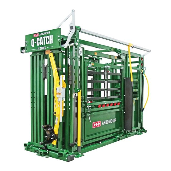
- Page 1 PRODUCT MANUAL ® MOBILE Q-CATCH 74 SERIES CRUSH, RACE, & FORCING PEN 7408 OCTOBER 2021 01530 632002 | cs@arrowquip.com arrowquip.co.uk...
-
Page 3: Table Of Contents
CONTENTS Safety Precautions Risk Assessment Transporting the Q-Catch 74 Series Portable Working System Requirements Reference for Manual Jacks To Lower Unit for Use To Raise Unit for Transport Using the Q-Catch Cattle Crush Operating the Q-Catch Cattle Crush Q-Catch Yoke Gate Assembly Emergency Yoke Gate Release Yoke Gate &... -
Page 4: Safety Precautions
All farm machinery and equipment is potentially dangerous. Careless use of any Arrowquip livestock equipment may cause injury or damage to persons, cattle, or property. Arrowquip has taken precautions in the design and manufacturing of this product to ensure that it is safe and user- friendly. -
Page 5: Risk Assessment
RISK ASSESSMENT Conduct a risk assessment on procedures for which the equipment is used and establish a safe work procedure. 1. Ensure all users of the equipment have been inducted and comply with safe working procedure. 2. Please ensure that there are NO large or hazardous objects inside the equipment that may cause injury to the animal or operator, or may cause the equipment to malfunction. -
Page 6: To Lower Unit For Use
TO LOWER UNIT FOR USE: Extend the front jack to the ground and unhook the unit from towing vehicle. Remove the hitch from the unit. 3 | TRANSPORTING THE Q-CATCH 74 SERIES MOBILE WORKING SYSTEM... - Page 7 Using the front jack, lower the crush to the ground. Transfer the front jack to the race section. At this point, both jacks should be attached to either side of the race. TRANSPORTING THE Q-CATCH 74 SERIES MOBILE WORKING SYSTEM | 4...
- Page 8 Using both jacks simultaneously, raise the unit until the tires are 1" above the ground. Remove tires and set aside. WARNING: BOTH JACKS SHOULD ALWAYS BE AT THE SAME HEIGHT TO KEEP THE UNIT BALANCED. Using both jacks simultaneously, lower the unit until the forcing pen section is 3-6" above the ground.
- Page 9 Remove the pin and pull out the bottom joiner bar. Secure with the same pin. Loosen the ratchet strap and safety chain. Set aside. WARNING: HOLD THE PANELS WHILE RELEASING THE STRAP TO PREVENT THE TUB FROM UNFOLDING UNINTENTIONALLY. RATCHET STRAP CHAIN TRANSPORTING THE Q-CATCH 74 SERIES MOBILE WORKING SYSTEM | 6...
- Page 10 Unfold the panels and attach to the bottom joiner bar. Attach the top joiner bars to the panels as shown. 7 | TRANSPORTING THE Q-CATCH 74 SERIES MOBILE WORKING SYSTEM...
- Page 11 Using both jacks simultaneously, lower the unit to the ground completely. READY FOR USE TRANSPORTING THE Q-CATCH 74 SERIES MOBILE WORKING SYSTEM | 8...
-
Page 12: To Raise Unit For Transport
TO RAISE UNIT FOR TRANSPORT: Push crowd gate up against the swing gate. Return the top joiner bars to their respective holders. Secure the top left joiner bar with the pin. 9 | TRANSPORTING THE Q-CATCH 74 SERIES MOBILE WORKING SYSTEM... - Page 13 Using both jacks simultaneously, raise the unit until the forcing pen section is 3-6" above the ground. Fold curved panels in on one another. TRANSPORTING THE Q-CATCH 74 SERIES MOBILE WORKING SYSTEM | 10...
- Page 14 Secure panels with the ratchet strap and transport chain as shown. Tighten the ratchet strap to prevent sag in panels during transport. WARNING: HOLD THE PANELS WHILE TIGHTENING THE STRAP TO PREVENT THE TUB FROM UNFOLDING UNINTENTIONALLY. RATCHET STRAP CHAIN Retract the bottom joiner bar and secure with the pin.
- Page 15 Using both jacks simultaneously, raise the unit 12-14" above the ground. Install tires, and retract jacks completely. WARNING: BOTH JACKS SHOULD ALWAYS BE AT THE SAME HEIGHT TO KEEP THE UNIT BALANCED. Transfer the right rear jack to the front of the unit. TRANSPORTING THE Q-CATCH 74 SERIES MOBILE WORKING SYSTEM | 12...
- Page 16 Using the front jack, raise the crush 3" above the ground. Install the hitch and secure with the pin. Connect the unit to the towing vehicle. Adjust the hitch to the proper position for the vehicle, if necessary. Retract the front jack completely. NOTE: Ensure all jacks are retracted for transport BEFORE DRIVING.
-
Page 17: Using The Q-Catch Cattle Crush
USING THE Q-CATCH 74 SERIES CATTLE CRUSH This section contains: • Operating the Q-Catch 74 Series • Assembling the Q-Catch Yoke Gate • Emergency Yoke Gate Release • Yoke Gate & Squeeze Conversion • Q-Catch 74 Series Add-Ons OPERATING THE Q-CATCH 74 SERIES ENSURE ALL CRUSH FUNCTIONS AND ADD-ONS ARE WORKING PROPERLY BEFORE OPERATING. -
Page 18: Emergency Yoke Gate Release
10. Q-CATCH ROLLER BOLT EMERGENCY YOKE GATE RELEASE Arrowquip cattle crushes are designed to ensure the safety of both animal and operator. With proper maintenance and lubrication, the yoke gate will not jam under pressure. However, in the rare event that an animal becomes stuck in the yoke gate, the following guidelines will ensure you are able to release your animal quickly and safely. - Page 19 Insert screwdriver/pry bar into the small space above the spring in the yoke gate lock plate. EMERGENCY YOKE GATE RELEASE | 16...
-
Page 20: Yoke Gate & Squeeze Conversion
YOKE GATE & SQUEEZE CONVERSION Arrowquip cattle crushes can be ordered based on your preferred operating side. In the rare event that you would need to operate the yoke gate and squeeze on the opposite side, please contact your local dealer for additional parts and follow these instructions. - Page 21 LEFT-HAND TO RIGHT-HAND NOTE: Switching from Left-hand to Right-hand operation shown. For Right-hand to Left-hand operation, complete the steps from the opposite side. SET PARTS ASIDE TOGETHER WITH THE CORRESPONDING BOLTS AND WASHERS. Remove the Q-Catch shield. Remove the yoke gate hammer and squeeze arm plate. YOKE GATE &...
- Page 22 Remove the control tube and Q-Catch handle. Detach the control tower vertical tube. Unbolt the shaft, rotate to align with the second hole, and secure. 19 | YOKE GATE & SQUEEZE CONVERSION...
- Page 23 Install the control tower vertical tube and fasten with bolts. Flip the squeeze axle welding on the rear control bracket and transfer it to the opposite side. YOKE GATE & SQUEEZE CONVERSION | 20...
- Page 24 Feed the control tube through the control tower vertical tube. Insert the Q-Catch handle and mount the control tube on the rear control bracket. Secure with a bolt on the opposite side. 21 | YOKE GATE & SQUEEZE CONVERSION...
- Page 25 Install the squeeze arm plate. Install the yoke gate hammer and connect it to the squeeze arm plate. YOKE GATE & SQUEEZE CONVERSION | 22...
- Page 26 Install the Q-Catch Shield. SQUEEZE THE CRUSH TO REMOVE THE FANDANGLE. Remove the Left-hand fandangle and squeeze bracket. B (x2) 23 | YOKE GATE & SQUEEZE CONVERSION...
- Page 27 Install the squeeze bracket and Right-hand fandangle on the opposite side. RIGHT-HAND FANDANGLE DO NOT TIGHTEN BOLTS UNTIL STEP 22 Unmount the Left-hand squeeze lockbox. Set aside. YOKE GATE & SQUEEZE CONVERSION | 24...
- Page 28 Detach the squeeze bracket. Transfer the squeeze bracket to the opposite side. 25 | YOKE GATE & SQUEEZE CONVERSION...
- Page 29 Mount the right-hand squeeze lockbox. RIGHT-HAND LOCKBOX Detach the middle tie rod. YOKE GATE & SQUEEZE CONVERSION | 26...
- Page 30 Remove bolt from A and transfer to B. Attach the middle tie rod as shown. 27 | YOKE GATE & SQUEEZE CONVERSION...
- Page 31 Secure bolts on the squeeze bracket and fandangle. BEFORE WORKING WITH ANIMALS, SAFETY CHECK: All parts have been reinstalled correctly ✓ All crush functions, including the yoke gate and squeeze mechanisms, are ✓ working properly. ✓ All bolts are tightened correctly ✓...
-
Page 32: 3Rd Generation Q-Catch Head Scoop
Q-CATCH 74 SERIES ADD-ONS 3rd GENERATION Q-CATCH HEAD SCOOP For complete information, read the Head Restraint manual. REQUIREMENTS: - 2 people - 3/4" wrench Installation: a. Insert 4x1/2-13x3" carriage bolts through the yoke gate door from inside the crush. b. Align the head scoop to the slots in the yoke gate according to your desired height. Secure the head scoop with 4 bolts. -
Page 33: Sheeted Sternum Bar
Safety Precautions: 1. Ensure that the head scoop remains open until required to hold the animal’s head. 2. If not in use, use detent pin to hold the head holder in place. Maintenance: 1. Add grease through the grease nipples as needed. 2. -
Page 34: Clipping Rail
SAFETY CHECK: ✓ Ensure that the sternum bar is installed correctly before running cattle through the crush. Safety Precautions: 1. Remove the sternum bar when working calves. CLIPPING RAIL Installation: Place both brackets on the crush. Attach the clipping rail to the bottom bracket. 31 | Q-CATCH 74 SERIES ADD-ONS... -
Page 35: Easy Flow Race Section
Insert the clipping rail into the top bracket. Adjust clipping rail position to your preference. Tighten bolts to secure. Safety Precautions: 1. Ensure the clipping rail is installed and secured correctly before running cattle through the crush. EASY FLOW RACE This section contains: •... - Page 36 1. Pull the adjustment cable between the slam latches to release the panel. 2. Adjust the panel to the desired position. 3. Lock the panel into position with slam latches. BOTH LATCHES SHOULD BE SECURELY FASTENED IN THE PARALLEL ADJUSTMENT SLOTS BEFORE PROCEEDING. 4.
-
Page 37: Using The Emergency Exit
USING THE EMERGENCY EXIT In the event of a downed animal or other emergency, you can use the emergency exit to release livestock from the raceway. Exercise caution when releasing livestock, as they may act in unpredictable and/or uncharacteristic ways while distressed. Watch the emergency exit demo here: youtu.be/4eVA-R1v1bo REQUIREMENTS: - 2 people... -
Page 38: Scale Platform Installation
SCALE PLATFORM INSTALLATION REQUIREMENTS: - 2 people Installation: Adjust the race width to the narrowest setting. Lift the side panel and set the latch above the race bow. Repeat step for the opposite side panel. WARNING: THE PANELS ARE VERY HEAVY. YOU WILL NEED AT LEAST 2 PEOPLE TO LIFT EACH PANEL. - Page 39 Slide Scale Platform underneath. SCALE PLATFORM INSTALLATION | 36...
-
Page 40: Rolling Door Switch
Lower the side panels back to working position. Safety Precautions: 1. Please ensure that the scale platform is installed correctly, and side panels are properly latched before running cattle through the unit. ROLLING DOOR SWITCH REQUIRED TOOLS: - 9/16" wrench - 2x 3/4"... - Page 41 Remove rolling door handle slider. Remove the rolling door from the main frame. ROLLING DOOR SWITCH | 38...
- Page 42 Remove the rolling door track plate, and switch to the opposite side. Remove the rolling door bumpers and move to the opposite side 39 | ROLLING DOOR SWITCH...
- Page 43 Install the rolling door and secure to the main frame. Install the rolling door handle slider on the right-hand side. Remove the rolling door lock and move to the opposite side. ROLLING DOOR SWITCH | 40...
-
Page 44: Collapsible Forcing Pen
• General Equipment Maintenance • Cattle Crush Maintenance • Wheel Maintenance All Arrowquip Products are made with precision parts to require minimal maintenance. However, regular maintenance will keep your equipment running smoothly and safely. REGULAR MAINTENANCE (EVERY 6 MONTHS) 1. General Maintenance Inspect the entire unit. - Page 45 Lubricate slam latches and door hinges with WD-40 Dry Lube. ✓ Check gate latches and striker plates for wear. Ensure gates are locking securely. ✓ 2. Cattle Crush Inspect the yoke gate. ✓ a. Bolts on the yoke gate hammers should be tensioned correctly. There should be enough play for the hammers to move freely in their slots.
- Page 46 b. You should feel the yoke gate rollers moving when you open the yoke gate. The rollers should be tight enough to be moved by hand, but not over-tight to cause the rollers to bind. ✓ Clean bottom yoke gate door track to prevent dirt-build-up. Clean the crush floor.
- Page 47 2. Adjust the squeeze lock settings. a. Loosen jam nuts, and back out front and rear bolts. b. Push/pull the squeeze handle to get a visual of the release pin. c. Apply inward pressure on the squeeze handle. Adjust rear bolt until there is 1/4" - 3/8" gap between the fandangle and release pin.
-
Page 48: Only When Necessary
e. When the adjustment is set, re-tighten jam nuts to lock adjustment in place. - Tightening = less push - Loosening = more push - You will not have to push the release pin very far to enable release. FRICTION LOCK MAINTENANCE 1. -
Page 49: Troubleshooting Guide
TROUBLESHOOTING GUIDE If you have a problem with your Q-Catch 87 Series Mobile Working System, please consider the following tips or call us at 01530 632002. YOKE GATE 1. Make sure the unit is situated on level ground or base. 2. -
Page 50: Recommended Use
WARRANTY Your product must be registered to claim warranty, and to ensure that Arrowquip has the required information to contact you in the event of a product or part recall. Any owner who fails to register their product warranty with Arrowquip through their Authorised Arrowquip Dealer voluntarily voids their warranty. - Page 52 If you have any questions regarding your product or require assistance, please contact Arrowquip’s Client Care Team at 01530 632002 or by email at cs@arrowquip.com. Printed in Canada | October 2021...
Need help?
Do you have a question about the MOBILE Q-CATCH 74 Series and is the answer not in the manual?
Questions and answers