Table of Contents
Advertisement
Quick Links
Advertisement
Table of Contents
Troubleshooting

Related Manuals for Exabyte VXA-2 AUTOPAK1X7


Summary of Contents for Exabyte VXA-2 AUTOPAK1X7
- Page 1 VXA-2 A XABYTE UTOLOADER RODUCT ANUAL 1010964-000...
- Page 2 Copyright 2002 by Exabyte Corporation. All rights reserved. This item and the OPYRIGHT information contained herein are the property of Exabyte Corporation. No part of this document may be reproduced, transmitted, transcribed, stored in a retrieval system, or translated into any language or computer language in any form or by any means,...
- Page 3 Physical abuse or use not consistent with the operating instructions or product specifications. Repair or modification by any one other than Exabyte’s personnel or agent in a manner differing from the maintenance instructions provided by Exabyte. Removal of the Exabyte identification label(s).
- Page 4 1-800-392-8273 (Exabyte Media) To return equipment for service Exabyte Service 1-303-417-7791 (US) Teleplan-800-673-5719 (Canada) 1-303-417-7199 (fax) Note: If it is more convenient to your location, contact Exabyte Technical Support in Europe at the following numbers: Phone: +31-30-254-8890 Fax: +31-30-258-1582 1010964 RODUCT ANUAL...
-
Page 5: Table Of Contents
Contents About This Manual ......vii 1 1 1 1 Product Overview ......1 Autoloader Features ................. - Page 6 5 5 5 5 Maintenance........53 Cleaning the Autoloader ..............54 Using Touch-Up Paint on the Housing ..........
-
Page 7: About This Manual
BOUT ANUAL BOUT ANUAL This manual describes how to install, configure, operate, maintain, and troubleshoot the Exabyte VXA-2 AutoPak Autoloader. It also provides autoloader specifications. HERE TO OOK FOR NFORMATION Installation If you are performing first-time installation: Read Chapter 1 for an overview of the autoloader’s features and... - Page 8 ELATED UBLICATIONS The following publications provide additional information for the autoloader. Exabyte VXA-2 Tape Drive Exabyte VXA-2 SCSI Tape Drive Quick Start, 1009540 Exabyte VXA-2 SCSI Tape Drive Product Manual, 1009541 Exabyte VXA-2 SCSI Tape Drive SCSI Reference, 1009566 TANDARDS ANSI Small Computer System Interface (SCSI-2), X3.131-1994...
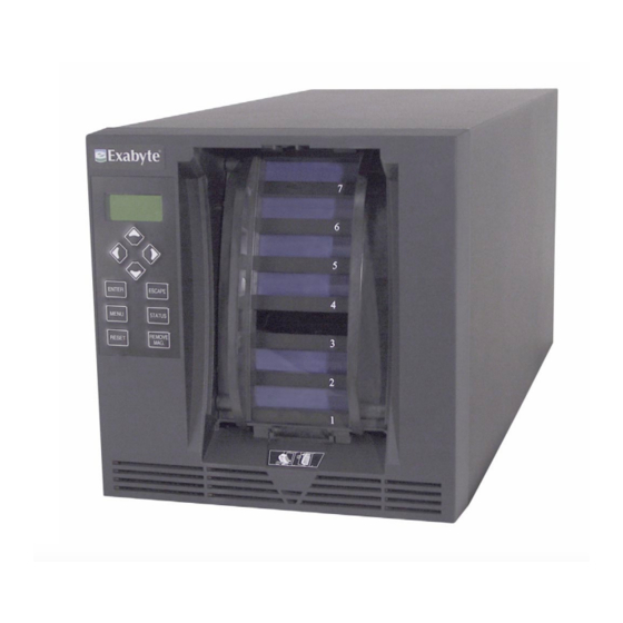
- Page 9 RODUCT VERVIEW Congratulations on selecting the Exabyte ® VXA-2 AutoPak Autoloader with the Exabyte VXA-2 tape drive. The VXA-2 AutoPak Autoloader (AutoPak ) is the ideal first step into automated data storage, providing affordable, convenient automated backup and restore for small- to medium-sized office environments. Occupying just 1 cubic foot of space, the AutoPak is optimized for desktop applications.
-
Page 10: Product Overview
Tabletop or rack-mount configuration. The autoloader is designed as a tabletop unit, but can also be mounted in a standard 19-inch rack. If desired, you can mount two autoloaders side-by-side on a single rack shelf. Rack-mounting kits are available from Exabyte. 1010964 RODUCT... -
Page 11: Autoloader Components
UTOLOADER OMPONENTS UTOLOADER OMPONENTS The following sections describe the autoloader’s front panel, internal, and back panel components. RONT ANEL OMPONENTS Figure 1-1 shows the autoloader’s front panel components. Keypad Cartridge magazine S T A Figure 1-1 Front panel components LCD and keypad (operator panel). The two-line LCD (liquid crystal display) and keypad allow you to view the operational status of the autoloader, access a menu of operations, and view status messages. - Page 12 Chapter 1 P RODUCT VERVIEW NTERNAL OMPONENTS Figure 1-2 shows the autoloader’s internal components. Tape drive Robot Magazine present sensor Figure 1-2 Internal components Robot. The robot moves a cartridge between the magazine and the tape drive. Magazine present sensor. The magazine present sensor detects whether the cartridge magazine is installed.
- Page 13 UTOLOADER OMPONENTS ANEL OMPONENTS Figure 1-3 shows the autoloader’s back panel components. Power entry module SCSI connectors 9-pin serial port Figure 1-3 Back panel components Fan. The fan reduces the autoloader’s operating temperature. Power entry module. The power entry module includes the AC power connector and the power switch.
- Page 14 Chapter 1 P RODUCT VERVIEW Notes 1010964 RODUCT ANUAL...
-
Page 15: Hardware Installation
ARDWARE NSTALLATION This chapter describes how to install the autoloader. Installation involves the following steps: Unpacking the autoloader Obtaining accessories and equipment Preparing for installation Preparing and installing cartridges Connecting the autoloader to the SCSI bus Powering on the autoloader Verifying the hardware installation 2002 VXA-2 A... -
Page 16: Unpacking The Autoloader
Chapter 2 H ARDWARE NSTALLATION NPACKING THE UTOLOADER To unpack the autoloader, remove the packing material and lift the autoloader out of the box. Note: Save all the original packing materials, including the accessory box, in case you need to ship or move the autoloader later. To remove the shipping braces: 1. - Page 17 NPACKING THE UTOLOADER b. b. b. b. Pull both of the side supports out of the autoloader. Side supports Cross-brace Figure 2-2 Removing the shipping braces 2002 VXA-2 A CTOBER XABYTE AK1x7 UTOLOADER...
-
Page 18: Obtaining Accessories And Equipment
One wide, multi-mode (single-ended/LVD) SCSI cable may be included with the autoloader. You can purchase additional cables from Exabyte or provide your own. Follow these guidelines when selecting SCSI cables: ! Use wide LVD SCSI cables that conform to SCSI-3 specifications. -
Page 19: Preparing For Installation
REPARING FOR NSTALLATION Table 2-1 Accessories and equipment for installation and operations (continued) Accessories and Equipment Rack-mount If you want to install the autoloader in a rack, contact Exabyte for hardware the required kit. (optional) Serial cable If you want to connect to the autoloader’s Console interface for firmware upgrades and diagnostics, use a straight-through 9-pin serial cable (not a null modem cable). -
Page 20: Preparing And Installing Cartridges
Chapter 2 H ARDWARE NSTALLATION REPARING AND NSTALLING ARTRIDGES This section describes how to prepare cartridges and install them in the autoloader. 1. 1. 1. 1. Verify that the write-protect switch on each cartridge is set correctly, as shown in Figure 2-3. - Page 21 REPARING AND NSTALLING ARTRIDGES 4. 4. 4. 4. Insert cartridges into each slot. Avoid touching or opening the cartridge dust cover when handling the cartridges. Caution Make sure the cartridge is inserted as shown in Figure 2-4, or you may damage the magazine when you place it into the autoloader.
-
Page 22: Connecting The Autoloader To The Scsi Bus
Although LVD SCSI is compatible with single-ended SCSI, Important Exabyte does not support single-ended devices on the autoloader’s LVD SCSI bus. To connect the autoloader to the SCSI bus: 1. 1. 1. 1. -
Page 23: Powering On The Autoloader
OWERING ON THE UTOLOADER 4. 4. 4. 4. If the autoloader is not the last device on the bus, connect a SCSI cable from the unused SCSI connector to the next device on the bus, as shown in Figure 2-7. From host To next device Figure 2-7... -
Page 24: Verifying The Hardware Installation
Is the host computer system powered on? Is the SCSI cable connected to the autoloader and host computer? Is there an error code displayed on the autoloader LCD? (See Chapter If you cannot resolve the problem yourself, contact Exabyte Technical Support (see page iv). -
Page 25: Configuring The Autoloader
ONFIGURING THE UTOLOADER After installing the autoloader, you are ready to set basic configuration options. This chapter describes how to: Access configuration options through the operator panel Set configuration options Check the setup 2002 VXA-2 A CTOBER XABYTE AK1x7 UTOLOADER... -
Page 26: Using The Operator Panel
Chapter 3 C ONFIGURING THE UTOLOADER SING THE PERATOR ANEL The autoloader includes an operator panel consisting of a two-line LCD and a keypad (shown in Figure 3-1). The operator panel allows you to interactively control autoloader operations. You can set autoloader options, check operating statistics, and exercise autoloader hardware. - Page 27 SING THE PERATOR ANEL SING THE PERATOR Use the keys on the operator panel to perform the operations described in Table 3-1. Table 3-1 Operator panel keys Keys Operations Scrolls up or down through the menus or increases or [3] [4] decreases option values.
- Page 28 The robot control Mode) modes are SCSI, Sequential, LCD, and Console. SCSI Allows you to set SCSI IDs for the autoloader and drive, allows you to set Exabyte 210 emulation, and shows the current settings. 1010964 RODUCT ANUAL...
- Page 29 SING THE PERATOR ANEL Table 3-2 Main menus available from the operator panel (continued) Menu Description Seq Opt Allows you to set Loop, Restart, and Next Cart to 1, and shows (Sequential the current settings. Options) Serial Allows you to set the baud rate of the autoloader’s serial port. Autoldr Info Allows you to view the code versions, system statistics, system (Autoloader...
-
Page 30: Setting Configuration Options
Chapter 3 C ONFIGURING THE UTOLOADER ETTING ONFIGURATION PTIONS Configuring the autoloader involves setting options based on your specific needs. Configuration tasks include: Setting the SCSI IDs Setting the emulation mode, if necessary Setting Sequential mode options, if necessary Setting the robot control mode Setting the LCD security option The following sections provide step-by-step instructions for each of these tasks. - Page 31 ETTING ONFIGURATION PTIONS 3. 3. 3. 3. Press [ENTER]. The following screen appears: S C S I D 0 1 A 0 0 4. 4. 4. 4. If you want to change the current settings, press [ENTER]. The message Set SCSI IDs flashes on the screen, then the following screen appears: D 0 1 A 0 0...
- Page 32 Exabyte EZ17 autoloader, you can select an option that allows the autoloader to emulate an Exabyte 210 library. Changing the emulation mode causes the autoloader to return “EXB-210” in response to a SCSI INQUIRY command from an application. Because most applications are certified for the Exabyte 210 library,...
- Page 33 ETTING ONFIGURATION PTIONS ETTING EQUENTIAL PTIONS When the autoloader is operating in Sequential mode, its internal firmware instructs the robot to move cartridges sequentially between the cartridge slots and the tape drive. No application software is required to support cartridge movement.
- Page 34 Chapter 3 C ONFIGURING THE UTOLOADER To set the Sequential mode options: 1. 1. 1. 1. From the Status screen, press [MENU]. The following screen appears: S e c u r t y D i s a b l e d 2.
- Page 35 ETTING ONFIGURATION PTIONS 9. 9. 9. 9. Press [3] or [4] until you see the setting you want. If you want Restart on, press [ENTER] when the LCD displays 1. If you want Restart off, press [ENTER] when the LCD displays 0. The Restart Option screen shows the new setting. 10.Press [ENTER] to display the Next Cartridge screen: N e x t C a r t :...
- Page 36 Chapter 3 C ONFIGURING THE UTOLOADER ETTING THE OBOT ONTROL The robot control mode determines the source of commands issued to the robot to move cartridges. The available control modes are described in Table 3-4. After you select a control mode, it remains in effect until you change it.
- Page 37 ETTING ONFIGURATION PTIONS 3. 3. 3. 3. Press [3] or [4] to scroll through the Main Menu until you see the following screen: R o b o t S C S I 4. 4. 4. 4. Press [ENTER]. The following message flashes on the screen: Select I/F that controls robotic motions Then, the following screen appears: R o b o t ?
- Page 38 Chapter 3 C ONFIGURING THE UTOLOADER You can set security in either of two ways: You can set the security option from the LCD, as described in this section. The application software can issue a SCSI MODE SELECT command to enable or disable security (see your software documentation).
- Page 39 ETTING ONFIGURATION PTIONS Disabling Security From the LCD 1. 1. 1. 1. From the Status screen, press [MENU]. The following screen appears: S e c u r t y L C D Note: If the menu displays Disabled, the security option is already disabled.
-
Page 40: Checking The Setup
If there is an error code displayed on the LCD, page 67 for a list of error codes and corrective actions. If you cannot solve the problem yourself, contact your service provider or Exabyte (see page iv). 1010964... -
Page 41: Operating The Autoloader
PERATING THE UTOLOADER After you have configured the autoloader, you can put it into operation. Your autoloader application automatically controls the autoloader’s robotics (unless you are using Sequential mode), while your backup application controls backup and restore jobs. Before beginning operation, always make sure that: The tape drive does not have a cartridge loaded. -
Page 42: Removing And Replacing The Magazine
Chapter 4 O PERATING THE UTOLOADER EMOVING AND EPLACING THE AGAZINE This section describes removing and replacing the magazine to access the cartridges and the tape drive. EMOVING THE AGAZINE To remove the magazine: 1. 1. 1. 1. Release the magazine by pressing [REMOVE{ { { { { M AG] and following the instructions on the screen. - Page 43 EMOVING AND EPLACING THE AGAZINE NSTALLING THE AGAZINE Use only magazines designed for the Exabyte VXA-2 Important AutoPak Autoloader. Do not use Exabyte magazines designed for other Exabyte libraries. Before installing the magazine, make sure there is not a cartridge in the drive. If you install the magazine when there is a cartridge in the drive, the autoloader cannot complete its power-on self-test, resulting in an error.
-
Page 44: Cleaning The Tape Drive
Do not use any cleaning method other than the VXAtape Cleaning Cartridge (or a Caution cleaning cartridge approved by Exabyte for use with VXA drives). Using other cleaning methods may void the tape drive’s warranty. Do not rewind and reuse the material in a cleaning cartridge. Reuse may redistribute contaminants previously removed from the tape path. - Page 45 LEANING THE RIVE 2. 2. 2. 2. Insert the cleaning cartridge into the tape drive. The drive automatically performs the cleaning process in less than one minute and ejects the cartridge when the process is complete. Do not touch the Magazine Present sensor when inserting or removing the Caution cleaning cartridge.
-
Page 46: Ejecting A Cartridge Manually
Chapter 4 O PERATING THE UTOLOADER JECTING A ARTRIDGE ANUALLY If a problem occurs that requires intervention, you may need to manually eject the cartridge from the tape drive. To manually eject the cartridge: 1. 1. 1. 1. Park the robot and remove the magazine, as follows: a. -
Page 47: Monitoring The Tape Drive's Leds
’ ONITORING THE RIVE 3. 3. 3. 3. Remove the cartridge from the drive. Eject button LEDs Figure 4-3 Location of tape drive’s eject button and LEDs ’ ONITORING THE RIVE The VXA-2 tape drive’s faceplate has four LEDs, shown in Figure 4-3, that indicate the drive’s operational status. - Page 48 Retry the operation. If the problem persists, try power cycling the drive to clear the error. If you cannot resolve the problem yourself, contact Exabyte Technical Support. You may need to return the drive for service; contact Exabyte Technical Support. The tape was written without a valid end-of-data mark, which often occurs if you power-down the drive while the drive was writing.
-
Page 49: Resetting The Autoloader And Tape Drive
ESETTING THE UTOLOADER AND RIVE ESETTING THE UTOLOADER AND RIVE If the autoloader or tape drive has encountered an error and is still not operating after you have tried the recommended corrective action, you may need to perform a reset. Before resetting the autoloader and tape drive, make sure they are not Caution communicating across the SCSI bus. - Page 50 Chapter 4 O PERATING THE UTOLOADER IEWING UTOLOADER ERSIONS The Autoldr Info Menu contains information about the flash code level and the boot code level. To view code levels: 1. 1. 1. 1. Select Autoldr Info Menu from the Main Menu, then scroll until you see the following screen: C o d e V e r s i o n s...
- Page 51 IEWING UTOLOADER AND RIVE NFORMATION In this example, n is the total number of times the robot has picked a cartridge and placed it in the drive or a cartridge slot. 3. 3. 3. 3. To view the other system statistics, press [3] or [4] until you see the statistic you want.
- Page 52 Chapter 4 O PERATING THE UTOLOADER 2. 2. 2. 2. Press [ENTER] to view the system sensor information. The following screen appears: M a g a z n e " L o c k e d : n In the preceding example, n indicates whether the magazine is locked (1) or unlocked (0).
- Page 53 IEWING UTOLOADER AND RIVE NFORMATION IEWING UTOLOADER NVENTORY NFORMATION The autoloader stores inventory information in nonvolatile RAM and uses the information to process SCSI commands from the application software. The inventory contains information about the following element locations: Cartridge slots Tape drive Robot To view the Inventory Menu:...
- Page 54 Chapter 4 O PERATING THE UTOLOADER Table 4-4 Autoloader inventory information Element info Description Occup Indicates whether the autoloader considers the specified element location to contain (Occupied) a cartridge (1) or not (0). Valid Indicates whether the Occupied flag is accurate (1) or questionable (0). (Occupied Valid) Access (Tape Indicates whether a cartridge is loaded in the drive (0) or the drive is empty or the...
- Page 55 IEWING UTOLOADER AND RIVE NFORMATION IEWING RIVE TATUS NFORMATION To view tape drive status information: 1. 1. 1. 1. Select Drive Info Menu from the Main Menu. 2. 2. 2. 2. Press [ENTER] to display the Drive Info Menu. The following screen appears: D r i v e S t a t u s 3.
-
Page 56: Performing Hardware Exercises
Chapter 4 O PERATING THE UTOLOADER 4. 4. 4. 4. To view additional drive information, press [4] from the Drive Info Menu and then press [ENTER] to display the Drive Display screen. The following screen appears: D r i v e D i s p l a y Table 4-6 lists the messages that can appear on the Drive Display screen. - Page 57 ERFORMING ARDWARE XERCISES Figure 4-4 shows the element indexes assigned for the autoloader. Robot Tape Drive Data cartridge magazine Data cartridge slot Figure 4-4 Element index assignments SING THE Before running the demo: 1. 1. 1. 1. Disable security if it is enabled (see page 31).
- Page 58 Chapter 4 O PERATING THE UTOLOADER 5. 5. 5. 5. Press [1] or [2] to move the screen arrow to the digit you want to change, then press [3] or [4] to select the number you want. 6. 6. 6. 6. Press [ENTER] to start the demo.
- Page 59 ERFORMING ARDWARE XERCISES Table 4-7 Hardware exercises available through the Command Menu (continued) Test Description Additional instructions Home Robot Moves the robot to its home position in front of the drive. Cycle Pick/Put Causes the robot to take a When you select Cycle Pick/Put, the Cycle PP Src? cartridge from a specified screen appears.
-
Page 60: Storing Cartridges
Chapter 4 O PERATING THE UTOLOADER TORING ARTRIDGES After you have filled cartridges with data, you may want to store them outside of the autoloader to make room for additional cartridges. To maximize the shelf life of your cartridges and ensure data integrity, follow these storage guidelines: Store cartridges in a suitable environment. -
Page 61: Maintenance
AINTENANCE This chapter describes basic autoloader maintenance tasks, including: Cleaning the autoloader Using touch-up paint on the housing Upgrading firmware and creating diagnostic listings 2002 VXA-2 A CTOBER XABYTE AK1x7 UTOLOADER... -
Page 62: Cleaning The Autoloader
® use VXA2Tool, a Windows -based program available from the Exabyte web site at www.exabyte.com. VXA2Tool allows you to upgrade firmware and perform diagnostics over the SCSI bus attached to the autoloader. This section describes how to do the following: Connect to the autoloader’s Console interface... - Page 63 A host computer that uses an RS232 serial port A straight-through 9-pin serial cable (not a null modem cable) Terminal emulation software, such as HyperTerminal Note: Exabyte recommends using HyperTerminal, a standard communications ® package included with Microsoft Windows Connecting the Serial Cable 1.
- Page 64 Chapter 5 M AINTENANCE 2. 2. 2. 2. In the example above, nnnnn is the current baud rate for the autoloader. 3. 3. 3. 3. To change the autoloader’s baud rate, press [ENTER]. The following screen appears: B a u d R a t n n n n n 4.
- Page 65 PGRADING IRMWARE AND REATING IAGNOSTIC ISTINGS 5. 5. 5. 5. Check the ASCII setup from HyperTerminal: a. a. a. a. From the File menu, select Properties. b. b. b. b. In the Properties screen, select the Settings tab. c. c. c. c. In the Emulation mode field, select “ANSI.”...
- Page 66 Chapter 5 M AINTENANCE Setting the Autoloader to Console Mode Set the autoloader to Console mode by following these steps: 1. 1. 1. 1. Press [MENU]. The following screen appears: S e c u r t y D i s a b l e d 2.
- Page 67 PGRADING UTOLOADER IRMWARE VIA ONSOLE Do not upgrade firmware unless Exabyte Technical Support has advised you to do Caution so. If performed improperly, the upgrade procedure can render your autoloader inoperable. Consult with Exabyte Technical Support before performing an upgrade.
- Page 68 ISTING VIA ONSOLE If you report a problem to Exabyte Technical Support, you may be asked to create an autoloader diagnostic listing (also called a dump) via the Console interface. A diagnostic listing is created when you use a terminal emulation program (such as HyperTerminal) to send an ASCII text copy of the diagnostic buffer from the autoloader to the host computer.
- Page 69 PGRADING IRMWARE AND REATING IAGNOSTIC ISTINGS 5. 5. 5. 5. Press Enter again to start transferring the ASCII text file. 6. 6. 6. 6. When the transfer is complete, select the Transfer menu, then select Capture Text and Stop. LCD P IEWING THE ASSWORD VIA ONSOLE...
- Page 70 You can download new firmware from www.exabyte.com or you can contact Exabyte Technical Support for firmware. Do not upgrade firmware unless Exabyte Technical Support has advised you to do Caution so. If performed improperly, the upgrade procedure can render your tape drive inoperable.
-
Page 71: Troubleshooting And Error Codes
ROUBLESHOOTING AND RROR ODES This chapter provides basic troubleshooting information for the autoloader and defines error codes that may appear on the autoloader’s operator panel. 2002 VXA-2 A CTOBER XABYTE AK1x7 UTOLOADER... -
Page 72: Troubleshooting
Compatibility. Make sure that your autoloader and tape drive are ✔ compatible with the application software you plan to use. Contact Exabyte Technical Support or your sales representative for the latest compatibility information. 1010964... - Page 73 Firmware level. Make sure your autoloader contains the correct versions of ✔ boot code and firmware. To check the current code levels, see page 42. To determine whether you have the latest versions, check the Exabyte web site at www.exabyte.com. 2002 VXA-2 A CTOBER...
- Page 74 ✔ DVANCED ROUBLESHOOTING If you report a problem to Exabyte Technical Support, you may be asked to create a diagnostic listing. To create a diagnostic listing, you can use the autoloader’s serial port and Console interface program. For more information...
-
Page 75: Error Codes
This section describes the error codes that appear on the autoloader’s operator panel and provides corrective actions. Most autoloader components can be replaced only by Exabyte-approved service Caution providers. If you cannot find an obstruction or other obvious cause for the problem, contact your service provider. - Page 76 Chapter 6 T ROUBLESHOOTING AND RROR ODES Table 6-1 Autoloader error codes (continued) Code Description Corrective action ! Make sure there is nothing blocking the robot or the tape CHM full wrong time. There drive. was a cartridge in the robot at the wrong time.
- Page 77 RROR ODES Table 6-1 Autoloader error codes (continued) Code Description Corrective action ! Make sure the autoloader is not being used by any host, Theta home sensor. Robot then reset the autoloader from the operator panel. If home sensor failure. necessary, power the autoloader off and back on to reset Slot detect failure.
- Page 78 [RESET] on the operator panel. unexpected int; SCSI int stuck error. There is a SCSI chip ! If the error persists, contact your service provider or Exabyte failure. Technical Support. You may be asked to supply a diagnostic listing;...
- Page 79 RROR ODES Table 6-1 Autoloader error codes (continued) Code Description Corrective action ! Remove the magazine and look for anything that might be CHM full before move. There obstructing the robot. was a cartridge in the robot before a move operation, ! Make sure the autoloader is not being used by any host, initialize element status, or then reset the autoloader from the operator panel.
- Page 80 Chapter 6 T ROUBLESHOOTING AND RROR ODES Notes 1010964 RODUCT ANUAL...
-
Page 81: Shipping The Autoloader
If you need to return the autoloader for service, first contact your service provider. If your service provider instructs you to return the autoloader directly to Exabyte, contact Exabyte Technical Support to obtain a Return Materials Authorization (RMA) number and the shipping address (see “Contacting Exabyte”... -
Page 82: Preparing The Autoloader For Shipping
Chapter 7 S HIPPING THE UTOLOADER REPARING THE UTOLOADER FOR HIPPING To prepare the autoloader for shipping: 1. 1. 1. 1. Remove the magazine as described on page 2. 2. 2. 2. Remove all cartridges from the magazine. Make sure the robot and the tape drive do not contain cartridges. - Page 83 REPARING THE UTOLOADER FOR HIPPING 6. 6. 6. 6. Push the picker all the way into the robot as follows: a. a. a. a. Push the picker toward the back of the autoloader until it stops (see Figure 7-2). Cartridge picker Figure 7-2 Positioning the picker for shipping...
- Page 84 Chapter 7 S HIPPING THE UTOLOADER 7. 7. 7. 7. Angle one side support in through the front of the autoloader and place it between the side of the autoloader and the flipper. Be sure to push the side supports all the way in so they rest on the ESD shield (see Figure 7-4).
-
Page 85: Removing The Autoloader From A Rack
EMOVING THE UTOLOADER FROM A 10.Insert the free end of the cross-brace into the remaining side support. The shipping braces should be positioned as shown in Figure 7-6. Figure 7-6 Proper position of shipping braces 11.Reinstall the magazine as described on page EMOVING THE UTOLOADER FROM A... - Page 86 Chapter 7 S HIPPING THE UTOLOADER 3. 3. 3. 3. Remove the four screws that secure the bottom of the autoloader to the tray, and lift the autoloader off the tray (see Figure 7-8). Figure 7-8 Removing the autoloader from the tray 1010964 RODUCT ANUAL...
-
Page 87: Packing The Autoloader
ACKING THE UTOLOADER ACKING THE UTOLOADER Use the original packing materials to pack the autoloader. You will also need banding material. To avoid damaging the autoloader and voiding your warranty, be sure to use the Caution original shipping materials (or replacement materials obtained from your vendor) when repacking and shipping the autoloader. - Page 88 Chapter 7 S HIPPING THE UTOLOADER 4. 4. 4. 4. Place the top cushion over the autoloader. 5. 5. 5. 5. Place any necessary paperwork in the top of the autoloader box. 6. 6. 6. 6. Close and seal the box. 7.
-
Page 89: Specifications
PECIFICATIONS This appendix provides the following information about the autoloader: Storage capacity Size and weight Performance specifications Power specifications Environmental specifications Shipping specifications Safety and regulatory agency compliance 2002 VXA-2 A CTOBER XABYTE AK1x7 UTOLOADER... -
Page 90: Storage Capacity
(assuming a 2:1 compression ratio). RIVE ERFORMANCE When installed in the autoloader, the tape drive performs within its specifications. For information about tape drive performance specifications, refer to the Exabyte VXA-2 SCSI Tape Drive Product Manual. 1010964 RODUCT ANUAL... - Page 91 ERFORMANCE PECIFICATIONS UTOLOADER OWER Each time the autoloader is powered on, it performs a power-on self-test (POST). During POST, the autoloader: Performs self-diagnostics and boots up Moves the robot to the home position (in front of the tape drive) Checks for cartridges in each slot If the cartridges are properly installed, the autoloader is ready for operation.
-
Page 92: Power Specifications
Appendix A—S PECIFICATIONS OWER PECIFICATIONS This section describes autoloader AC input voltages and power consumption and lists the power cord specifications. AC I NPUT OLTAGES AND OWER ONSUMPTION The autoloader includes an internal power supply that accepts 100 VAC to 240 VAC at 50 Hz to 60 Hz. -
Page 93: Environmental Specifications
NVIRONMENTAL PECIFICATIONS NVIRONMENTAL PECIFICATIONS This section describes the following environmental specifications for the autoloader: General environmental specifications Particulate contamination limits Acoustic noise limits Shock and vibration limits ENERAL NVIRONMENTAL PECIFICATIONS Table A-1 lists general environmental specifications for the autoloader. Table A-1 Environmental specifications Storage , non-operating Specification... - Page 94 Appendix A—S PECIFICATIONS Figure A-1 is a psychrometric chart that indicates the operating temperature and humidity ranges for the autoloader. The dotted line represents the operating environment limits. Table A-2 defines the temperature and humidity points shown in Figure A-1. Table A-2 Temperature and humidity points for psychrometric chart Point Dry Bulb Temperature...
- Page 95 ONTAMINATION IMITS The ambient operating environment for the autoloader should not exceed the particulate counts specified for the tape drive. For more information, refer to the Exabyte VXA-2 SCSI Tape Drive Product Manual. COUSTIC OISE IMITS The overall, averaged A-weighted sound pressure level (in decibels) for the...
- Page 96 Appendix A—S PECIFICATIONS Table A-5 lists the vibration specifications for the autoloader during operation, non-operation, storage, and transportation. The operating specifications indicate the amount of vibration the autoloader can withstand while the enclosed tape drive is reading and writing data. Table A-5 Vibration limits Random vibration applied during operation...
-
Page 97: Shipping Specifications
HIPPING PECIFICATIONS HIPPING PECIFICATIONS The autoloader’s carton and internal packing pieces are designed so that the enclosed autoloader does not receive a shock greater than 30 g when the carton is dropped on any surface, corner, or edge from a height of 30 inches (76.2 cm). -
Page 98: Safety And Regulatory Agency Compliance
Subpart B: Unintentional Radiators According to FCC regulations, changes or modifications to the Important autoloader that are not expressly approved by Exabyte may void the user’s authority to operate the autoloader. Industry Canada Notice, ICES-003, Class B, Digital Apparatus CISPR Publication 22, 1987 (EN 55022), Class B... - Page 99 Compatibility (EMC), Part 4: Testing and Measurement Techniques, Part 2: Electrostatic Discharge (ESD) Immunity. Exabyte has extended testing as follows: Up to 12,000 volts air discharge applied to all non-metallic surfaces Up to 8,000 volts direct discharge applied to all metallic/conductive surfaces In each case, there is no degradation or non-recoverable loss of function due to damage of equipment or firmware.
- Page 100 Appendix A—S PECIFICATIONS ONDUCTED ADIO REQUENCY IELD MMUNITY The autoloader complies with EN 61000-4-6:1996, Electromagnetic Compatibility (EMC), Part 6: Conducted Radio Frequency Immunity. The autoloader will continue to operate without error while being exposed to a field of 3Vrms. OLTAGE NTERRUPTIONS ARIATIONS MMUNITY...
-
Page 101: Index
NDEX cartridges accessing 210 emulation manually ejecting See emulation mode moving using Diagnostics menu obtaining storing troubleshooting problems AC power specifications cleaning accessories autoloader LED indicators for packing for shipment required for operation tape drive acoustic noise limits cleaning cartridge requirements addresses, element using... - Page 102 LCD Escape key description location Drive Status screen ESD protection Main Menu Exabyte 210 emulation Status screen See emulation mode LCD mode LCD security See security LEDs, tape drive states fan, location Loop option firmware, upgrading...
- Page 103 NDEX maintenance cleaning the autoloader rack space creating diagnostic listings upgrading firmware regulatory agency compliance using touch-up paint reliability Menu key Remove Mag key description location using Next Cart option removing the shipping braces noise limits Reset key description using to reset autoloader resetting autoloader and tape drive operating environment Restart option...
- Page 104 NDEX serial port configuring for diagnostics unload button connecting 9-pin cable location unpacking the autoloader setting the autoloader’s baud rate upgrading autoloader firmware service, returning autoloader shipping braces installing removing vibration specifications shipping specifications voltage specifications shipping the autoloader shock specifications size weight software...
Need help?
Do you have a question about the VXA-2 AUTOPAK1X7 and is the answer not in the manual?
Questions and answers