
Related Manuals for TSC Prontronix TTP-244CE


Summary of Contents for TSC Prontronix TTP-244CE
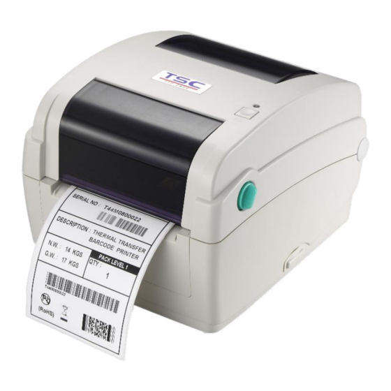
- Page 1 TTP-244CE Thermal Transfer Direct Thermal Desktop Barcode Printers User Manual...
- Page 2 All other trademarks are the property of their respective owners. Information in this document is subject to change without notice and does not represent a commitment on the part of TSC Auto ID Technology Co. No part of this manual may be reproduced or transmitted in any form or by any means, for any purpose other than the purchaser’s personal use, without the...
-
Page 3: Table Of Contents
Table of Contents 1. Introduction ........................................1 2. Operation Overview ......................................2 2.1 Unpacking and Inspection ....................................2 2.2 Printer Overview ......................................3 2.2.1 Front View ......................................3 2.2.2 Interior View ......................................4 2.2.3 Rear View ......................................5 3. Setup ..........................................6 3.1 Setting up the Printer ....................................6 3.2 Instructions to Top Cover Operation................................7 3.3 Loading the Ribbon ......................................8 3.4 Loading the Media ..................................... - Page 4 4.2 Regular Button Function .................................... 15 4.3 Power-on Utilities ....................................... 16 5. TSC Console ........................................17 5.1 Start TSC Console ..................................... 17 5.2 Setup Ethernet Interface .................................... 19 5.3 Printer Function ......................................21 5.4 Setting Post-Print Action .................................... 22 6. TroubleShooting ......................................23 7.
-
Page 5: Introduction
This document provides an easy reference for operating this printer. TSC printers include the Windows labeling software for creating your label template. For system integration, the TSPL/TSPL2 printer programming manual or SDKs can be found on TSC website at: https://www.tscprinters.com. -
Page 6: Operation Overview
2. Operation Overview 2.1 Unpacking and Inspection This printer has been specially packaged to withstand damage during shipping. Please carefully inspect the packaging and printer upon receiving the bar code printer. Please retain the packaging materials in case you need to reship the printer. ... -
Page 7: Printer Overview
2.2 Printer Overview 2.2.1 Front View Ribbon access cover Media view window LED indicator Feed button Top cover open lever SD card socket... -
Page 8: Interior View
2.2.2 Interior View Ribbon rewind hub Ribbon rewind gear Gap sensor (receiver) Media holder Media holder lock switch Gap sensor (transmitter) Printhead Ribbon supply hub Top cover support Media guide adjustment knob Black mark sensor Platen roller... -
Page 9: Rear View
2.2.3 Rear View Fan-fold paper entrance chute Ethernet interface USB interface Centronics interface RS-232C interface Power jack socket Power switch... -
Page 10: Setup
3. Setup 3.1 Setting up the Printer Place the printer on flat surface. Make sure the printer is power off. Connect the printer to the computer with the provided USB cable. Plug in the power cord. Note: Please switch OFF the printer before plugging in the power cord to printer power jack. -
Page 11: Instructions To Top Cover Operation
3.2 Instructions to Top Cover Operation Pull the tabs located on each side towards the front Open the printer top of the printer, then lift the cover. top cover to the maximum open angle. A top cover support at Hold the top cover and the rear of the printer press the top cover support will engage with lower... -
Page 12: Loading The Ribbon
3.3 Loading the Ribbon Insert the ribbon right side Open the printer top onto the supply hub. Align cover and the ribbon the notches on the left side access cover. and mount onto the spokes. Insert the paper core right side onto the rewind hub. - Page 13 Loading Path for Ribbon...
-
Page 14: Loading The Media
3.4 Loading the Media Place the roll between the Open the printer top holders then put it onto the cover and separate the media holders. core. Press down the media Place the paper and make holder lock switch to sure the printing side is facing up. -
Page 15: External Label Roll Mount Installation (Option)
3.5 External Label Roll Mount Installation (Option) Insert a 3” label spindle into Attach an external a paper roll. And install it on paper roll mount on the the external paper roll bottom of the printer. mount. Open the printer’s top cover and separate the Disengage the top cover support and close the top... -
Page 16: Loading Fan-Fold Media
3.6 Loading Fan-fold Media Insert the fan-fold media Open the printer top through the external label cover. entrance chute. Separate and hold Press down the media open the media holder lock switch to hold holders. the media firmly. Place the paper, printing side face up. -
Page 17: Loading Label In Peel-Off Mode (Option)
3.7 Loading Label in Peel-Off Mode (Option) Open the printer top cover. Refer to section 3.4. to load the media then feed the paper. Use software to set the media sensor type and calibrate the selected sensor.( Please refer to chapter 4 and 5) Lead the media through the Open the peel-off panel backing paper opening and... -
Page 18: Loading Label In Cutter Mode (Option)
3.8 Loading Label in Cutter Mode (Option) Open the printer top cover. Refer to section 3.4. to load the media then feed the paper. Lead the media through the cutter paper opening. Move the media guides to fit the label width by turning the guide adjuster knob. Disengage the top cover support and close the top cover gently. -
Page 19: Led And Button Functions
4. LED and Button Functions 4.1 LED Indicator Color Meaning Solid: Power is on and ready to be used. (Green) Flash :System is downloading data or printer is paused. System is clearing data. (Amber) Solid - Printer head open, cutter error. (Red) Flash - Printing error, such as paper empty, paper jam, ribbon empty, or memory error etc. -
Page 20: Power-On Utilities
4.3 Power-on Utilities Power-on Utilities provides the basic functions and can be activated by below procedures: Turn off the power > Hold the Feed button > Open the power > Release the button depending on the the color of the LED. Sequences of the settings: LED Colors Green... -
Page 21: Tsc Console
5. TSC Console TSC Console is a management tool combining the Printer Management, Diagnostic Tool, CommTool and Printer Webpage settings, which enables you to adjust printer’s settings/status; change printers’ settings; download graphics, deploy fonts, graphics, label templates or upgrade the firmware to the group of printers, and send additional commands to printers at the same time ※... - Page 22 Select the current interface of the printer. The printer will be added to TSC Console’s interface. Select the printer and set the settings. For more information, please refer to TSC Console User Manual.
-
Page 23: Setup Ethernet Interface
5.2 Setup Ethernet Interface Use USB or COM to establish the interface on TSC Console. Double click to enter the Printer Configuration Page > Click Ethernet tab > Check the IP Address. - Page 24 Choose Network > Key in the IP Address > Click Discover to establish the Ehternet interface. The notification will pop up > Click OK to close the window > The Ethernert interface will be shown on TSC Console.
-
Page 25: Printer Function
5.3 Printer Function Printer Function could be found in Printer Configuration. “Printer Function” will be shown on the left side of the window. Functions Description Calibrate Sensor Detect media types and the size of the label RTC Setup Synchronize printer with Real Time Clock on PC Factory Default Initialize the printer to default settings Reset Printer... -
Page 26: Setting Post-Print Action
When the printer is equipped with other opton kits, ex: cutter, peeler, rewinder, please select the mode after finishing the calibration. Follow below procedure to set the post action for the printing: Refer Chp 5.1 to Connect the printer with TSC Console > Double click the printer >... -
Page 27: Troubleshooting
6. TroubleShooting This section lists the common problems that according to the LED status and other problems you may encounter when operating the printer. Also, it provides solutions. LED Status LED Status / Color Printer Status Possible Cause Recovery Procedure * Turn on the power switch. - Page 28 Print Problem Problem Possible Cause Recovery Procedure Check if interface cable is well connected to the Re-connect cable to interface. interface connector. The serial port cable pin configuration is not pin to pin Please replace the cable with pin to pin connected. connected.
- Page 29 Adjust the print density and print speed. Check if print density is set properly. Check print head test pattern if head element is Run printer self-test and check the print head test pattern if there is dot missing in the pattern. damaged.
-
Page 30: Maintenance
7. Maintenance This session presents the clean tools and methods to maintain the printer. For Cleaning Depending on the media used, the printer may accumulate residues (media dust, adhesives, etc.) as a by-product of normal printing. To maintain the best printing quality, you should remove these residues by cleaning the printer periodically. Regularly clean the print head and supply sensors once change a new media to keep the printer at the optimized performance and extend printer life. - Page 31 Cleaning Tools Cotton swab Lint-free cloth Brush with soft non-metallic bristles Vacuum cleaner 75% Ethanol (for disinfecting) 99% Isopropyl alcohol (for printhead and platen roller cleaning) Genuine printhead cleaning pen Mild detergent (without chlorine) Cleaning Process: Printer Part Method...
-
Page 32: Angency Compliance And Approvals
8. Angency Compliance and Approvals EN 55032, Class B EN 55024 EN 60950-1; EN 61000-3-2; EN 61000-3-3 FCC part 15B, Class B ICES-003, Class B This equipment has been tested and found to comply with the limits for a Class B digital device, pursuant to part 15 of the FCC Rules. - Page 33 UL 60950-1(2nd Edition) CSA C22.2 No. 60950-1-07(2nd Edition) EN 60950-1 GB 4943.1 GB 9254, Class B GB 17625.1 Energy Star for Imaging Equipment Version 2.0 TP TC 004/2011 TP TC 020/2011 IS 13252(Part 1)/ IEC 60950-1 KN 22 KN 24 Note: There may have certification differences in the series models, please refer to product label for accuracy.
- Page 34 7. Make sure to follow the correct power rating and power type indicated on marking label provided by manufacture. 8. Please refer to user manual for maximum operation ambient temperature. WARNING: Hazardous moving parts, keep fingers and other body parts away. CAUTION: (For equipment with RTC (CR2032) battery or rechargeable battery pack) Risk of explosion if battery is replaced by an incorrect type.
-
Page 35: Revise History
9. Revise History Date Content Editor...
Need help?
Do you have a question about the Prontronix TTP-244CE and is the answer not in the manual?
Questions and answers