Advertisement
Available languages
Available languages
Quick Links
Advertisement

Subscribe to Our Youtube Channel
Related Manuals for MODSTER Arrows Husky


Summary of Contents for MODSTER Arrows Husky
- Page 1 1800mm Husky Operating Manual...
- Page 2 Warnung: Dieses Handbuch enthält wichtige Informationen, mit denen Sie Ihr Modellflugzeug zuverlässig und sicher warten und betreiben können. Bitte lesen Sie die Anweisungen und Warnungen vor der Montage, Einrichtung oder Verwendung sorgfältig durch. Da es sich bei diesem Modellflugzeug um ein hoch entwickeltes Hobbyprodukt handelt, muss es unter Berücksichtigung der Sicherheit und des gesunden Menschenverstandes geflogen werden.
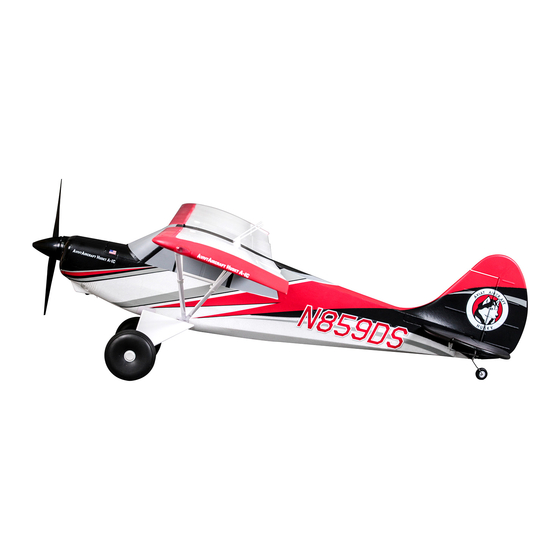
- Page 3 Einleitung Der 1800-mm-Husky ist ein von der PA-18 inspiriertes, hochflügeliges Leichtflugzeug, das 1986 seinen ersten Flug absolvierte. Arrows Hobby hat dieses Backcountry-Arbeitstier nachgebildet - von Nietlinien und Karosserieteilen bis hin zu den gutmütigen STOL-Flugeigenschaften - ohne jedoch Details zu übersehen. Der Arrows 1800mm Husky ist voller attraktiver Funktionen und verfügt über ein robustes CNC-Fahrwerk, übergroße Ballon- reifen und funktionale Klappen für echte Backcountry-Operationen.
- Page 4 Bauanleitung Fahrwerk-Installation 1. Schieben Sie das Fahrwerk bei umgedrehtem 2. Schieben Sie die Fahrwerkshalter in die Rumpf wie gezeigt in die Rumpfschlitze. Rumpfschlitze und befestigen Sie die Baugruppe mit den mitgelieferten Schrauben. HKM3.0*16mm Flügel-Installation 1. Schieben Sie den Flügelstange in den Rumpfdurch- 2.
- Page 5 Bauanleitung Flügel-Installation KA3.0*16mm HKM3.0*16mm 3. Schließen Sie bei umgekehrtem Rumpf das Querruderservo an und befestigen Sie den Flügel und die Flügelstreben mit den mitgelieferten Schrauben. Höhen- und Seitenleitwerk-Installation 1. Setzen Sie das Höhenleitwerk auf den Rump- ausschnitt. 2. Setzen Sie das Seitenleitwerk auf das Höhenleit- 3.
- Page 6 Bauanleitung Schubstangen-Installation 1. Verbinden Sie das Servo - bei zentriertem Servo 2. Verbinden Sie das Servo - bei zentriertem Servo und Höhenruder - mit dem Anlenkgestänge. und Seitenruder - mit dem Anlenkgestänge. Antennen-Installation Propeller- und Spinner-Installation 1. Platzieren Sie die Antennen wie gezeigt oben auf den 1.
- Page 7 Akku-Installation 1. Entfernen Sie die Verschlussklappe des Akkus. 2. Entfernen Sie das Klettband vom Rumpf. Bringen Sie die Schleifen-Seite am Akku an. 3. Setzen Sie den Akku in den Rumpf ein und sichern Sie ihn mit den vorinstallierten Bändern. Hinweis: Das Gewicht jedes Akkus kann aufgrund unterschiedlicher Herstellungstechniken variieren.
- Page 8 Vorflug-Check Sender- und Modellaufbau Stellen Sie nach der Montage und vor Ihrem ersten Flug sicher, dass alle Bedienoberflächen korrekt (wie auf dem Diagram unten angegeben) auf Ihren Sender reagieren. Ruderausschlag Die empfohlene Einstellung für den Ruderausschlag lautet wie folgt (Servo-Wegbegrenzung): ipp: Der Jungfernflug sollte immer mit kleinem Ausschlag geflogen werden.
- Page 9 Ruderhorn- und Servo-Arm-Einstellungen More control throw Horns Arms 1. Die Tabelle zeigt die Werkseinstellungen für die Ruderhörner und Servo-Arme. Fliegen Sie das Flug- zeug Werkseinstellungen, bevor Änderungen vornehmen. Less control throw 2. Nach dem Fliegen können Sie die Verbindung anpassen. Lastenschwerpunkt Das Einstellen des richtigen Schwerpunkts ist entscheidend, um sicher- zustellen, dass das Flugzeug stabil und reaktionsschnell arbeitet.
- Page 10 Vor dem Fliegen Schalten Sie Ihren Sender immer zuerst ein. Installieren Sie einen vollständig geladenen Akku im Akkufach und schließen Sie ihn an den Regler an. Stellen Sie bei diesem Vorgang sicher, dass die Gasfunktion aktiviert ist und der Gashebel in seiner niedrigsten Position gesichert ist.
- Page 11 Problembehebung Problem Möglicher Grund Solution Lower throttle stick and throttle trim to lowest Aircraft will not respond to ESC is not armed. settings. the throttle but responds to Throttle channel is reversed. other controls. Reverse throttle channel on transmitter. Damaged spinner, propeller, Replace damaged parts.
- Page 12 WARNING: This manual contains important information that will help you maintain and operate your model aircraft in a reliable and safe manner. Please read the instructions and warnings carefully prior to assembly, setup or use. As this model aircraft is a sophisticated hobby product, it must be flown with safety and common sense in mind, failure in doing so may result in injury or property damage.
- Page 13 Introduction The Husky is a PA-18 inspired, high-winged light utility aircraft which made its first flight in 1986. Arrows hobby has recreated this backcountry workhorse- from rivet lines and body panels to the predictable STOL flight characteristics- without overlooking any detail when creating the 1800mm Husky. Packed full of attractive features, the Arrows 1800mm Husky is prebuilt with a rugged CNC landing gear, oversized balloon tires and functional flaps for true STOL backcountry operations.
- Page 14 Model assembly Installation of the landing gear set 1. With the fuselage inverted, slide the landing gear 2. Slide the landing gear retainers into the fuselage into the fuselage slots as shown. slots and secure the assembly using the included screws.
- Page 15 Model assembly Wing installation KA3.0*16mm HKM3.0*16mm 3. With the fuselage inverted, connect the aileron servo wire then secure the wing and wing struts using the included screws. Horizontal and vertical stabilizer installation 1. Place the horizontal stabilizer onto the fuselage cutout.
- Page 16 Model assembly Pushrod installation 1. With the servo and elevator centered, connect the 2. With the servo and rudder centered, connect the servo to the control surface using a pushrod. servo to the control surface using a pushrod. Antenna installation Propeller and spinner installation 1.
- Page 17 Battery installation 1. Remove the battery hatch. 2. Remove the hook and loop tape from the fuselage. Apply the looped surface to the battery. 3. Install the battery into the fuselage- securing it with the preinstalled battery straps. Note: The weight of each battery may vary due to different manufacturing techniques.
- Page 18 Preflight check transmitter and model setup After assembly and prior to your first flight, make sure all control surfaces respond correctly to your transmitter by referring to the diagram below. Control throws The suggested control throw setting for the Husky are as follows (dual rate setting): Tips: The maiden flight should always be flown using low rates, fly the aircraft until you are famil- iar with its characteristics prior to trying high...
- Page 19 Control horn and servo arm settings More control throw Horns Arms 1. The table shows the factory settings for the control horns and servo arms. Fly the aircraft at the factory settings before making changes. Less control throw 2. After flying, you may choose to adjust the linkage positions for the desired control response.
- Page 20 Before flying the model Always turn your transmitter on first. Install a fully charged battery in the battery bay, then connect it to the ESC. In this process, make sure that the throttle cut functionality is on, and that the throttle stick is secured in its lowest position- other- wise, the propeller/fan will engage and possibly cause bodily harm.
- Page 21 Troubleshooting Problem Possible Cause Solution Lower throttle stick and throttle trim to lowest Aircraft will not respond to ESC is not armed. settings. the throttle but responds to Throttle channel is reversed. other controls. Reverse throttle channel on transmitter. Damaged spinner, propeller, Replace damaged parts.
Need help?
Do you have a question about the Arrows Husky and is the answer not in the manual?
Questions and answers