Table of Contents
Advertisement
Available languages
Available languages
Quick Links
Advertisement
Chapters
Table of Contents

Related Manuals for MODSTER Arrows P-47 980mm


Summary of Contents for MODSTER Arrows P-47 980mm
- Page 1 980mm P-47 Operating Manual...
- Page 2 Warnung: Dieses Handbuch enthält wichtige Informationen, mit denen Sie Ihr Modellflugzeug zuverlässig und sicher warten und betreiben können. Bitte lesen Sie die Anweisungen und Warnungen vor der Montage, Einrichtung oder Verwendung sorgfältig durch. Da es sich bei diesem Modellflugzeug um ein hoch entwickeltes Hobbyprodukt handelt, muss es unter Berücksichtigung der Sicherheit und des gesunden Menschenverstandes geflogen werden.
-
Page 3: Table Of Contents
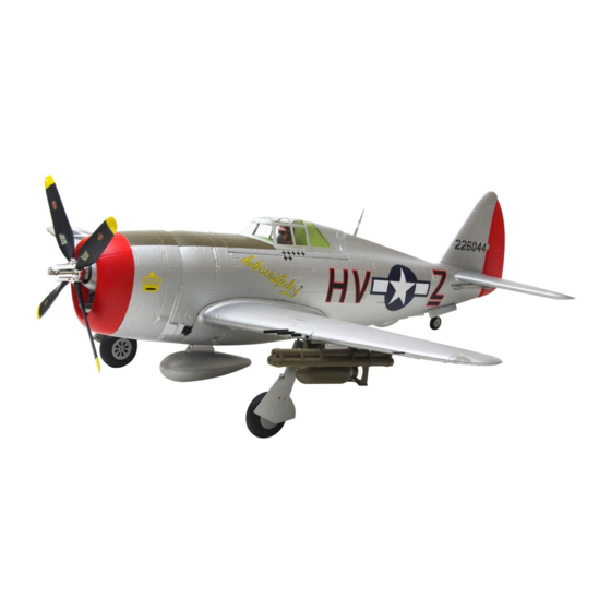
Einleitung Die Republic P-47 Thunderbolt war im 2. Weltkrieg ein Kampfflugzeug der US-Armee. Mit acht Tonnen Gewicht bei voller Beladung war es eines der schwersten Jagd- und Bodenangriffsflugzeuge seiner Zeit. Mit M8-Raketenhülsen und einer Nutzlast von 2500 Pfund war es äußerst effektiv. Arrow Works ist stolz darauf, den detailgetreuen 980 mm P-47 vorstellen zu können. -
Page 4: Bauanleitung
Bauanleitung HKM3.0*32mm Flügel-Installation 1. Legen Sie den Flügel am Rumpf an und achten Sie darauf, dass keine Servodrähte eingeklemmt werden. 2.Befestigen Sie den Flügel wie gezeigt mit den mitge- lieferten Schrauben am Rumpf. Ziehen Sie die Schrau- ben nicht zu fest an. Höhrenleitwerk-Installation 1.Schieben Sie die Höhenleitwerk-Stange in den Schlitz am Ende des Rumpfes. - Page 5 Bauanleitung Kraftstofftank-Installation Waffen-Installation 1.Tragen Sie vorsichtig einen schaumsicheren Kleber 1. Schieben Sie die Bomben und Raketen auf die auf Boden und Seite der Zusatztasche des Kraftstoff- Schienen. tanks auf und setzen Sie den Tank in die Tasche ein. Erforderliche Klebstoffe: Mittelflüssiger Sekunden-Kleber Antennen-Installation...
-
Page 6: Akku-Installation
Akku-Installation 1. Entfernen Sie die Verschlussklappe des Akkus. 2. Entfernen Sie das Klettband vom Rumpf. Bringen Sie die Schleifen-Seite am Akku an. 3. Setzen Sie den Akku in den Rumpf ein und sichern Sie sie mit den vorinstallierten Bändern. Hinweis: Das Gewicht jedes Akkus kann aufgrund unter- schiedlicher Herstellungstechniken variieren. -
Page 7: Gabelkopf-Installation
Vorflugkontrolle Sender- und Modellaufbau Stellen Sie nach der Montage und vor Ihrem ersten Flug sicher, dass alle Bedienoberflächen korrekt (wie auf dem Diagram unten angegeben) auf Ihren Sender reagieren. Höhenruder Ruderausschlag Die empfohlene Einstellung für den Ruderausschlag lautet wie folgt (Servo-Wegbegrenzung): Tipp: Der Jungfernflug sollte immer mit kleinem Ausschlag Großer Ausschlag Kleiner Ausschlag... -
Page 8: Vor Dem Fliegen
Ruderhorn- und Servo-Arm-Einstellungen Mehr Ruderausschlag Ruderhörner Arme 1. Die Tabelle zeigt die Werkseinstellungen für die Ruderhörner und Servo-Arme. Fliegen Sie das Flug- zeug Werkseinstellungen, bevor Änderungen vornehmen. Weniger Ruderausschlag 2. Nach dem Fliegen können Sie die Verbindung anpassen. Lastschwerpunkt Das Einstellen des richtigen Schwerpunkts ist entscheidend, um sicher- zustellen, dass das Flugzeug stabil und reaktionsschnell arbeitet. - Page 9 Vor dem Fliegen Schalten Sie Ihren Sender immer zuerst ein. Installieren Sie einen vollständig geladenen Akku im Akkufach und schließen Sie ihn an den Regler an. Stellen Sie bei diesem Vorgang sicher, dass die Gasfunktion aktiviert ist und der Gashebel in seiner niedrigsten Position gesichert ist.
-
Page 10: Problembehebung
Problembehebung Problem Möglicher Grund Lösung Gashebel und -trimmer auf niedrigsten Wert stellen. Flugzeug reagiert nicht auf Drehzahlregler (ESC) ausgeschaltet. Gashebel, aber auf andere Gaskanal seitenverkehrt eingestellt. Befehle Defekte Teile ersetzen. Spinner, Propeller, Motor o. Übermäßige Vibration oder Motorhalterung defekt. Teile an Propeller(-Adapter) und Spinner festziehen. Propellergeräusch. - Page 11 Warning: This manual contains important information that will help you maintain and operate your model aircraft in a reliable and safe manner. Please read the instructions and warnings carefully prior to assembly, setup or use. As this model aircraft is a sophisticated hobby product, it must be flown with safety and common sense in mind, failure in doing so may result in injury or property damage.
- Page 12 Introduction The Republic P-47 Thunderbolt was a World War II era fighter aircraft that served with the United States Army Air Forces. Weighing in at eight tonnes when fully loaded, it was one of the heaviest fighters and ground attack aircraft of its era. Carrying M8 rocket pods and a 2500lb payload of bombs, it was highly effective in ground attack missions.
-
Page 13: Model Assembly
Model assembly HKM3.0*32mm Wing installation 1. Attach the wing onto the fuselage, ensuring not to pinch any of the servo wires. 2.Attach the wing to the fuselage with included screws as shown. Do not over tighten the screws. Horizontal stabilizer installation 1.Slide the horizontal stabilizer spar into the slot near the rear of the fuselage. - Page 14 Model assembly Auxiliary fuel tank installation Armament installation 1.Carefully apply foam safe CA to the base and side of 1. Slide the bombs and rockets onto the rails. the auxiliary fuel tank pocket and place the oil tank into the pocket. Required Adhesives: Medium CA Antenna installation...
-
Page 15: Battery Installation
Battery installation 1. Remove the battery hatch. 2. Remove the hook and loop tape from the fuselage. Apply the looped surface to the battery. 3. Install the battery into the fuselage- securing it with the preinstalled battery straps. Note: The weight of each battery may vary due to different manufacturing techniques. -
Page 16: Clevis Installation
Preflight check transmitter and model setup After assembly and prior to your first flight, make sure all control surfaces respond correctly to your transmitter by referring to the diagram below. Control throws The suggested control throw setting for the P-47 are as follows (dual rate setting): Tip: The maiden flight should always be flown using low rates, fly the aircraft until you Elevator... -
Page 17: Control Horn And Servo Arm Settings
Control horn and servo arm settings More control throw Horns Arms 1. The table shows the factory settings for the control horns and servo arms. Fly the aircraft at the factory settings before making changes. Less control throw 2. After flying, you may choose to adjust the linkage positions for the desired control response. -
Page 18: Flying Course
Before flying the model Always turn your transmitter on first. Install a fully charged battery in the battery bay, then connect it to the ESC. In this process, make sure that the throttle cut functionality is on, and that the throttle stick is secured in its lowest position- other- wise, the propeller/fan will engage and possibly cause bodily harm. -
Page 19: Troubleshooting
Troubleshooting Problem Possible Cause Solution Lower throttle stick and throttle trim to lowest Aircraft will not respond to ESC is not armed. settings. the throttle but responds to Throttle channel is reversed. Reverse throttle channel on transmitter. other controls. Replace damaged parts. Damaged spinner, propeller, motor or motor mount.
Need help?
Do you have a question about the Arrows P-47 980mm and is the answer not in the manual?
Questions and answers