Page 1
All manuals and user guides at all-guides.com 
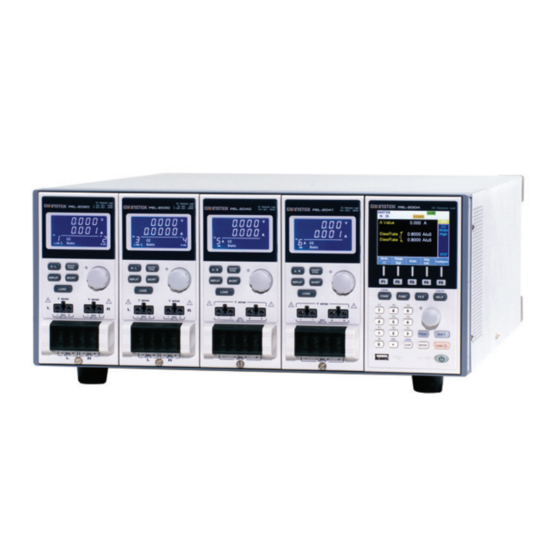
Programmable DC Electronic Load PEL-2000 Series USER MANUAL GW INSTEK PART NO. 82EL-20040MA1 ISO-9001 CERTIFIED MANUFACTURER...
Page 2
All manuals and user guides at all-guides.com March 2010 This manual contains proprietary information, which is protected by copyright. All rights are reserved. No part of this manual may be photocopied, reproduced or translated to another language without prior written consent of the Good Will company. The information in this manual was correct at the time of printing.
All manuals and user guides at all-guides.com Table of Contents Table of Contents SAFETY INSTRUCTIONS ........... 5 GETTING STARTED ............10 Main Features ........12 Series Overview ........13 Package Contents and Accessories..15 Measurement Overview ....... 16 Front Panel Overview ......17 Display Overview –...
Page 4
All manuals and user guides at all-guides.com PEL-2000 Series User Manual Frame Link ......... 104 Channel Control ......... 106 General Configuration Options ..108 OPERATION ..............109 Local Mode Operation ....... 112 Mainframe Basic Operation ....119 Channel Configuration ....... 160 ...
PEL-2002/PEL-2004, and when keeping it in storage. Read the following before operating the PEL-2002/2004 to ensure your safety and to keep the PEL-2000 series in the best possible condition. Safety Symbols These safety symbols may appear in this manual or on the PEL- 2002/2004.
Page 6
All manuals and user guides at all-guides.com PEL-2000 Series User Manual Do not dispose electronic equipment as unsorted municipal waste. Please use a separate collection facility or contact the supplier from which this instrument was purchased. Safety Guidelines Do not place any heavy object on the PEL- General ...
Page 7
All manuals and user guides at all-guides.com SAFETY INSTRUCTIONS AC Input voltage: 115V/230V switchable, Power Supply 50/60Hz WARNING The power supply voltage should not fluctuate more than 15%. Connect the protective grounding conductor of the AC power cord to an earth ground, to avoid electrical shock.
Page 8
All manuals and user guides at all-guides.com PEL-2000 Series User Manual Location: Indoor, no direct sunlight, dust free, Operation almost non-conductive pollution (Note below) Environment Temperature: 0°C to 40°C Altitude: Up to 2000m Transient Overvoltage on the main supply is ...
Page 9
All manuals and user guides at all-guides.com SAFETY INSTRUCTIONS Power cord for the United Kingdom When using the PEL-2002/2004 in the United Kingdom, make sure the power cord meets the following safety instructions. NOTE: This lead/appliance must only be wired by competent persons WARNING: THIS APPLIANCE MUST BE EARTHED IMPORTANT: The wires in this lead are coloured in accordance with the following code:...
Page 10
All manuals and user guides at all-guides.com PEL-2000 Series User Manual ETTING STARTED This chapter describes the features and functions of the PEL-2002/2004, including the front and rear panel appearance, panel installation and connection types. Use the Tutorial section for quick access to step by step instructions on the main functions.
The PEL-2000 series support three operation modes: constant current (CC), constant voltage (CV and CV+CC) and constant resistance (CR). Constant current and constant resistance mode can operate in either static or dynamic mode.
GPIB (optional) Series Overview The PEL-2000 series comprises of two different Mainframes: the PEL- 2002 and the PEL-2004. The Mainframes differ by the number of load modules that can be accommodated. The PEL-2002 has two load module slots whilst the PEL-2004 has 4. There are 4 different load module models, the PEL-2020, PEL-2030, PEL-2040 and PEL-2041.
Page 14
All manuals and user guides at all-guides.com PEL-2000 Series User Manual DC Electronic Load DC Electronic Load PEL-2002 DC Electronic Load 20A / 80V , 100W PEL-2020 PEL-2040 R 20A / 80V , 100W 70A / 80V , 350W STATIC/...
Description Accessories Power Cable Mains power cable (region dependent) User Manual PEL-2000 Series Electronic DC load User Manual (region dependent) GTL-120 Load cables 2X red, 2X black (per load module) GTL-121 Remote sense cables , 1X red, 1X black (per load...
All manuals and user guides at all-guides.com PEL-2000 Series User Manual Measurement Overview The PEL-2000 series has a number of different operating modes that are completely configurable. All the modes have customizable Go/NoGo limits, range limits, timers, slew rates, alarms and protection limits.
All manuals and user guides at all-guides.com GETTING STARTED Front Panel Overview PEL-2002 DC Electronic Load LCD display Function keys LOCAL UTILITY System Keys CHAN FUNC FILE HELP Selector Knob Number Pad Operation PRESET SHIFT CAL. LOCK keys ON / CLEAR ENTER LOAD...
Page 18
All manuals and user guides at all-guides.com PEL-2000 Series User Manual CHAN/LOCAL is used to select System Keys the load channel. Combined with the shift key, Local is used to activate/deactivate local control (during remote control via the interface or frame link connections).
Page 19
All manuals and user guides at all-guides.com GETTING STARTED Enter numerical values, or to Number pad save/recall presets (P0-P9). Number values. Preset numbers P0- Decimal point and Calibration key Decimal point. Activate calibration mode. Please note, calibration mode is not supported. Note Please see your distributor for calibration needs.
Page 20
All manuals and user guides at all-guides.com PEL-2000 Series User Manual Used to select operations and to Selector Knob increase/decrease values. When turned left or right moves the cursor in menus or changes the selected item or value. When pushed down, acts as the Enter key.
Page 21
All manuals and user guides at all-guides.com GETTING STARTED The shift key is used to access alternate functions assigned to select keys Inactive Active. When active the shift key can be used to access the Local and Utility menus. Confirms selections. Turns the current load/channel on or off Load is currently...
All manuals and user guides at all-guides.com PEL-2000 Series User Manual Display Overview – Mainframe The Mainframe Status Panel displays the status of Mainframe Status Panel the Mainframe interface, programs and alarm status. Frame Link Indicates Frame Link is Status...
Page 23
All manuals and user guides at all-guides.com GETTING STARTED Load Type The Load Type Icon LOAD indicates if a Sequence LOAD (SEQ) or Program (PROG) is turned on. If PROG not then LOAD is PROG displayed as default. When any Load type is running, their icon will turn orange.
Page 24
All manuals and user guides at all-guides.com PEL-2000 Series User Manual Mode Displays the current mode. Static / Displays whether the channel is in Dynamic Static or Dynamic mode. Range High Displays High or Low range. Go/NoGo SPEC If Go/NoGo is turned on, SPEC will be displayed.
All manuals and user guides at all-guides.com GETTING STARTED Rear Panel Overview PEL-2004 PEL-2002 Go/NoGo Output GPIB GO / NG OUTPUT RS232C RS232C SER. NO. LB GPIB FRAME CONT USB-B REPLACE FUSE AS SPECIFIED terminal FUSE RATING 115V T 3.15A 120 VA MAX 230V 250V...
Page 26
All manuals and user guides at all-guides.com PEL-2000 Series User Manual The RS232 and GPIB port is RS232 port/ used for remote control GPIB port connections. RS-232C: DB-9 pin male GPIB: 24-pin female See pages 233, 234 for remote control details.
Page 27
All manuals and user guides at all-guides.com GETTING STARTED The power supply socket Power Socket/ accepts the AC mains Voltage. Fuse The fuse holder is located below the power socket. Power: 50/60 Hz (180 VA) Fuse: T3.15A/250V For fuse replacement details see page 242.
All manuals and user guides at all-guides.com PEL-2000 Series User Manual Front Panel Overview – Load Module DC Electronic Load 20A / 80V , 100W PEL-2020 R 20A / 80V , 100W display Static/ Dynamic R/L A/B Key STATIC/ R / L DYNA.
Page 29
All manuals and user guides at all-guides.com GETTING STARTED Used to alternate the display Display Key output on the load module. Current Voltage Power Load time Activates the load for the active Load Key LOAD channel. (Right or Left)(A or B) The voltage sense terminals are Left Voltage used when precise measurement is...
Page 30
All manuals and user guides at all-guides.com PEL-2000 Series User Manual For 2 channel load modules, the left Positive and terminals are used for the 1 Negative Terminals Right channel and the right terminals are used for the 2 channel.
Page 31
All manuals and user guides at all-guides.com GETTING STARTED The SHORT key is used to Short Key manually short circuit the active channel on the local active load. When a load is off, the SHORT key will toggle the Short key type. Hold: Hold the SHORT key to short the channel load.
All manuals and user guides at all-guides.com PEL-2000 Series User Manual LED Display Overview – Load Module 1&2. Channel Display Left and right channel indicator. 5 digit display. Indicates the channel number 3&7. Channel (1-8). Number Indicator Indicates if the load is active on the load module.
Page 33
All manuals and user guides at all-guides.com GETTING STARTED 4. Mode Indicator The Mode Indicator LEDs will indicate what the current mode or settings are on the active channel(s). Value A or B for a single channel load module. Applies to CR, CV, and CC static mode only.
Page 34
All manuals and user guides at all-guides.com PEL-2000 Series User Manual Lights up when a load is shorted. Lights up when Go/NoGo is activated and the load fails (NG) the Go/NoGo limits. The Unit Indicators display current the 5&6. Channel unit.
All manuals and user guides at all-guides.com GETTING STARTED Installation The installation chapter describes how to load the different load modules, install the optional GPIB card, the rack mount kit and how to determine each channel number. Load Module Installation To avoid static electricity, please use appropriate anti- WARNING static work practices.
Page 36
4. Install any additional modules as described above. 5. If there are any slots empty, install the supplied panel cover (GW Instek part number: 63FP-AG106501). The panel cover will improve safety and increase air flow.
Page 37
All manuals and user guides at all-guides.com GETTING STARTED 6. Use the supplied screws to fix the panel cover(s) over the load slot.
All manuals and user guides at all-guides.com PEL-2000 Series User Manual GPIB Installation To avoid static electricity, please use appropriate anti- WARNING static work practices. The PEL-2004 and 2002 has GPIB as an option (GW GPIB Card installation Instek part no. PEL-001).
The PEL-2004 can be used in a standard 19” rack Background mount enclosure with the optional rack mount kit (GW Instek part no. 11EL-20040201). Each unit requires a rack height of 4U with a 1U space for ventilation top and bottom. The rear of the rack mount enclosure must be free of obstruction to allow heat to dissipate from the mainframe(s).
All manuals and user guides at all-guides.com PEL-2000 Series User Manual Channel Number The channel number for a module load is Description determined by which slot it occupies on the mainframe chassis. There can be 1 or 2 channels per slot, depending on the load module type.
All manuals and user guides at all-guides.com GETTING STARTED Power Up & Self Test 1. Connect the power cord Panel operation to the power socket. 2. Turn the external power switch on. 3. Hold the power button on the front panel to turn on the power.
Page 42
All manuals and user guides at all-guides.com PEL-2000 Series User Manual When the system check happens, the load modules will display each channel as it is checked, then display the current mode. 4. If any of the System checks fails, please power down the load generator and reinstall the appropriate load module(s).
All manuals and user guides at all-guides.com GETTING STARTED Load Connections Precautions and Procedures The PEL-2000 load generator supports a number of Intoduction different load configurations for flexible operation. Single DUT, single load Single DUT, parallel load Multiple DUTs, multiple loads ...
Page 44
All manuals and user guides at all-guides.com PEL-2000 Series User Manual Wires that are selected must be large enough to Wire Selection withstand a short circuit and limit voltage drops to no more than 2V per wire. Use the table below to help make a suitable selection.
Page 45
All manuals and user guides at all-guides.com GETTING STARTED The diagram above shows how changes in current can affect voltage. Load line inductance can be reduced by ensuring Limiting Load line load wires are as short as possible and by twisting inductance positive and negative load wires together.
Page 46
All manuals and user guides at all-guides.com PEL-2000 Series User Manual The PEL-2000 supports single and dual channel Load module load modules. considerations Single channel load modules have one bank of negative terminals and one bank of positive terminals. Each terminal pair has a 40A capacity.
Page 47
All manuals and user guides at all-guides.com GETTING STARTED 4. Close the terminal cover securely. Ensure the wires are secured properly and that the wires are not exposed when the cover is in place. Ensure that the wires are tied or twisted together to WARNING prevent noise and inductance.
All manuals and user guides at all-guides.com PEL-2000 Series User Manual Remote (Sense) Connection The electronic load modules have two voltage Background sense contacts: Vsense L(black), Vsense R(red). Voltage sense can be used to help compensate for long cable length. The longer the cable, the higher the potential resistance and inductance, therefore a short cable is best.
Page 49
All manuals and user guides at all-guides.com GETTING STARTED The voltage sense terminals use a screw-less clamp Remote Sense connector. The clamp must be opened prior to Terminal connection inserting a wire. Use a small screwdriver to push the clamp release mechanism. Insert both wires then release the clamp mechanism.
All manuals and user guides at all-guides.com PEL-2000 Series User Manual Single Load Connections A dual channel load module can be used to sink Dual Channel two loads concurrently. Load Module Connection On a single channel load module, the left terminals...
Page 51
Take into account any noise or irregularities from the auxiliary supply. The diagram below shows a typical connection. Using an auxiliary power supply may induce reverse WARNING current. The PEL-2000 series has reverse voltage protection. For details see the protection section on page 79.
All manuals and user guides at all-guides.com PEL-2000 Series User Manual Parallel Load Connections When the power output of a DUT exceeds the Parallel load modules power rating of a channel or load module, the channel terminals, load modules or mainframes can be used in parallel to dissipate more power when used in CC mode.
Page 53
All manuals and user guides at all-guides.com GETTING STARTED Parallel loads The PEL-2000 mainframes can also be connected in using framelink parallel. Please note, when using a frame link connections connection there is a delay between the master and the slave. Please see page 54 for details. Master Slave Slave...
All manuals and user guides at all-guides.com PEL-2000 Series User Manual Frame Link Connection Frame link control involves connecting multiple Background mainframes using the frame link connections. Up to 4 slave mainframes can be connected to the master mainframe. The first mainframe (master) can be used to control the other slave frames.
Page 55
All manuals and user guides at all-guides.com GETTING STARTED The first mainframe that is connected is the master frame; any additional frames are slave units. The ribbon cable connects to the master from connector 2, and the slave from connector 1. Each successive slave unit is connected in a cascading manner the same way.
All manuals and user guides at all-guides.com PEL-2000 Series User Manual Channel Control Connection The Channel Control connecters are located on the Background rear panel of each mainframe. There are two channel control connectors for each load slot, one for each channel, if applicable. The channel control connector is used to externally: Turn on/off loads.
Page 57
All manuals and user guides at all-guides.com GETTING STARTED The external voltage reference input must be External Voltage between 0~10V. Connection Ensure the external voltage reference is stable and has WARNING low noise. The External Voltage should be no more than 10V.
Page 58
All manuals and user guides at all-guides.com PEL-2000 Series User Manual The Voltage Monitor Output (VMON) and Current Voltage and Monitor Output (IMON) output the load input Current Monitor Output voltage and load input current as a percentage of rating current/voltage. Where 0 volts = 0% rating and 10 volts = 100% load input rating voltage or current.
All manuals and user guides at all-guides.com GETTING STARTED Go/NoGo Connection The Go/NoGo port is a 15 socket port. Each Background channel has a dedicated line for a Go/NoGo output. The ports are open-collector with active low (1.1V) indicating a pass and active high (30V) as fail (an alarm).
All manuals and user guides at all-guides.com PEL-2000 Series User Manual PERATING DESCRIPTION Operating Mode Description ........... 61 Constant Current Mode ......61 Constant Resistance Mode ....65 Constant Voltage Mode ......68 Run Program ..............71 Sequence ................ 74 Parallel Dynamic Loading ..........
All manuals and user guides at all-guides.com GETTING STARTED Operating Mode Description There are three basic operating modes: constant current (CC), Constant Resistance (CR), and Constant Voltage (CV/CV+CC). All channels operate using any of the modes. Each mode has a number of configurable options including slew rate, levels, protection modes, Go/NoGo and extensive save options.
Page 62
All manuals and user guides at all-guides.com PEL-2000 Series User Manual There are two selectable ranges for constant current Range mode: high and low range. Low range has a higher resolution, but a lower range. If the current exceeds the Low Range, High range must be used.
Page 63
All manuals and user guides at all-guides.com GETTING STARTED The slew rate is the rate at which the current will Slew rate increase to a set level. There are two slew rates: rising slew rate & falling slew rate. In CC mode the slew rate is defined as A/uS.
Page 64
All manuals and user guides at all-guides.com PEL-2000 Series User Manual CC Mode: Static:Go/NoGo Current Load Current NoGo NoGo Voltage GO is specified as between the Low and High Go/NoGo limits. NoGo is specified as outside the Go/NoGo limits.
All manuals and user guides at all-guides.com GETTING STARTED Constant Resistance Mode In Constant Resistance Mode the load units will Background linearly sink current and voltage to match a set resistance. CR mode has two different values (single load modules), two different ranges and rising and falling slew rates.
Page 66
All manuals and user guides at all-guides.com PEL-2000 Series User Manual Single Load Module CR mode supports Dynamic loading. Dynamic Dynamic Functions load has two resistance levels (Level 1&2), and two timers (Timer 1&2) to switch between the resistance levels. Rising and falling slew rates can be set to determine the speed at which the load generator switches between load levels.
Page 67
All manuals and user guides at all-guides.com GETTING STARTED...
All manuals and user guides at all-guides.com PEL-2000 Series User Manual Constant Voltage Mode In Constant Voltage Mode the load units will sink Background current whilst keeping the voltage constant. Single channel load modules support 2 values (A Value, B Value) and have an adjustable cut-off current limit.
Page 69
All manuals and user guides at all-guides.com GETTING STARTED CV Mode Voltage A value B value Time When using CV mode, a current limit can be set for CV + CC CV + CC mode. When the voltage input is greater than A Value (load voltage) then the channel will operate in CV mode if the input current is less than the current limit.
Page 70
All manuals and user guides at all-guides.com PEL-2000 Series User Manual Response Speed Response speed can be set to fast or slow. Fast response and slow response is determined by the load module specifications. Slow response speeds are suitable for large loads as quick current changes will induce induction which can cause large voltage drops.
All manuals and user guides at all-guides.com GETTING STARTED Run Program The Program function on the PEL-2000 series Background supports a total of 12 different programs at any one time with 10 sequences to each program. Up to 12 programs can be chained together. The Program function is able to create a number of Go/NoGo tests.
Page 72
All manuals and user guides at all-guides.com PEL-2000 Series User Manual P/F-Time Off – 0.1 ~ (On-time+Off-time)-0.1 Short Channel CH1 ~ CH8 Sequences are run sequentially to create a Program. Program There are 10 Sequences in each Program. If less than 10 Sequences are desired for a Program, any additional Sequences can be skipped (not run).
Page 73
All manuals and user guides at all-guides.com GETTING STARTED Go/NoGo Results If Go/NoGo limits have been configured, the Pass/Fail results for each channel will be displayed for all the sequences and programs.
All manuals and user guides at all-guides.com PEL-2000 Series User Manual Sequence The Sequence function is used to create high Background resolution load simulations. Each Sequence can be configured to create a unique load profile to accurately simulate loads in real time. Sequences are only applicable for CC (Static) and CR (Static) modes.
Page 75
All manuals and user guides at all-guides.com GETTING STARTED Up to 120 points can be used with each Sequence. Points Each point can have a different duration, slew rate and value. A new point can be inserted or deleted at any stage of a Sequence.
Page 76
All manuals and user guides at all-guides.com PEL-2000 Series User Manual If more than one Sequence is programmed on the On end load mainframe, the On End Load function allows a Sequence to configure its load on or off at the end of its sequence until the last sequence ends.
Page 77
All manuals and user guides at all-guides.com GETTING STARTED The Channel Duration Time Setting feature allows Channel Duration the point time duration of one Sequence to be Time Setting imported by another Sequence. If the receiving sequence doesn’t have enough points, more will be created (without values).
All manuals and user guides at all-guides.com PEL-2000 Series User Manual Parallel Dynamic Loading The PEL-2000 series of DC electronic loads support Background parallel dynamic loading. This simply means that when the load modules of a mainframe are connected in parallel and set to dynamic mode, they can perform dynamic tests synchronously following the same clock.
All manuals and user guides at all-guides.com GETTING STARTED Configurations Description There are a number of different configurations for the PEL series including protection modes, operating configurations, and file system configurations. The Configuration Description section describes what the different configurations are used for and how they can be relevant to different operations.
Page 80
All manuals and user guides at all-guides.com PEL-2000 Series User Manual When a load unit is operating in CR or CV mode, Over Current the unit may need over current protection to Protection prevent excessive current being sunk. Over current...
All manuals and user guides at all-guides.com GETTING STARTED Reverse voltage protection prevents reverse voltage Reverse voltage damage to the PEL-2000 series up to the specified Protection rating. When Reverse voltage protection has been tripped an alarm tone will sound until the reverse voltage is removed.
Page 82
All manuals and user guides at all-guides.com PEL-2000 Series User Manual Von Voltage is the voltage limit at which the load Von Voltage will start to sink current. There are two operation modes for Von Voltage: Von latched:ON and Von latched:OFF.
Page 83
All manuals and user guides at all-guides.com GETTING STARTED When short mode is on, the load unit can simulate a Short short circuit. Shorting can be individually set for each channel when programming sequences. To initiate a short circuit manually, the short key is used.
Page 84
All manuals and user guides at all-guides.com PEL-2000 Series User Manual Load Delay time is used to delay activating a load Load D-Time (up to 10 seconds) after the load key has been pressed. However the Load D-Time setting will...
All manuals and user guides at all-guides.com GETTING STARTED Channel Control External channel control is used with the Channel Background Control connectors. Each channel control connector can activate each load, monitor voltage and current and has an external voltage reference input. The voltage and current monitors output 0~100% of the rated current/voltage as a voltage of 0~10V.
Page 86
All manuals and user guides at all-guides.com PEL-2000 Series User Manual To determine the Percent Rating (voltage or current load input), use the following formula; External Voltage Load Input Rating VorA Where “Rating Vor A” is the rating voltage/current of the load module.
Page 87
All manuals and user guides at all-guides.com GETTING STARTED Voltage Monitor The input voltage, like the load input current can be externally monitored with the channel control connectors. The VMON pin of the channel control connector outputs a voltage of 0~10V to represent the load input voltage as a percentage (0~100%) of the rating voltage.
Page 88
All manuals and user guides at all-guides.com PEL-2000 Series User Manual A load is turned on when Load On input is set to Turning on the On (active low). A load is turned off when the Load Load On input is set to Off (active high).
The PEL series support RS232, GPIB and USB Background remote frame control. Only one type of connection is supported at any one time. For more information on remote control please see the GW Instek website at www.gwinstek.com or see your local distributor about the PEL-2000 programming manual.
Page 90
All manuals and user guides at all-guides.com PEL-2000 Series User Manual data type. Thus files are saved/recalled for each channel and each data type. Preset data can be saved into 10 memory slots for Preset Data each channel. Preset data contains the mode, range, CV response speed and Go/NoGo settings.
Page 91
All manuals and user guides at all-guides.com GETTING STARTED SEQ data contains Sequence data. SEQ data can SEQ Data only be saved to and from USB. SEQ refers to Sequence data, not Program sequences. Internal Format N/A (Internal buffer) External Format 20X0X_XX.A SEQ Contents SEQ data contains the following data;...
Page 92
All manuals and user guides at all-guides.com PEL-2000 Series User Manual Active Channel (CH01~08) CHAN Mode Static/Dynamic Range CV response speed Go/NoGo SPEC Test Entry Mode High Center When saving data to internal memory, either the...
Page 93
All manuals and user guides at all-guides.com GETTING STARTED Save/Recall USB In order to save data from a single channel to USB, data must first be saved to the internal memory. After data is saved to internal memory, all the files can be saved to USB.
All manuals and user guides at all-guides.com PEL-2000 Series User Manual To recall saved files, the reverse is not true. Files must be recalled to each channel separately. File Format Single Channel Filename format 1: PEL series Load module Memory data...
Page 95
All manuals and user guides at all-guides.com GETTING STARTED All Channel Directory Format 1: All Channel common directory name 2: Directory number: 0000 ~ 0099 All Channel File Format 1: PEL series Load module Memory data type: Preset data P020 = 2020 SEQ data Setup Data P030 = 2030...
All manuals and user guides at all-guides.com PEL-2000 Series User Manual UTORIALS (Step by Step Operations) Local loads ..............97 Single Channel Load ............99 Programming ..............101 Sequences ..............103 Frame Link ..............104 Channel Control ............. 106 General Configuration Options ........108...
All manuals and user guides at all-guides.com TUTORIALS Local loads Local mode operation is useful to quickly test loads using the load module control panel rather than the mainframe control panel. Local load modules can be configured to operate independently to the mainframe.
Page 98
All manuals and user guides at all-guides.com PEL-2000 Series User Manual Load module Selector knobs can Page 188 9. Independent be configured to be independent control to the mainframe. Display Measured or Set Values Page 192 10. Configure with the selector knob.
All manuals and user guides at all-guides.com TUTORIALS Single Channel Load Single channel loads are used to manually test a DUT quickly or to configure channel settings for Program Sequences using the mainframe panel. Step Description Details Choose the appropriate load Page 35 1.
Page 100
All manuals and user guides at all-guides.com PEL-2000 Series User Manual Set the Go/NoGo configurations, Page 177 9. Go/NoGo if applicable. Configure the protection modes. Page 162 10. Protection Modes Activate the load by pressing the 11. Run load key.
All manuals and user guides at all-guides.com TUTORIALS Programming When creating a Program Sequence or Chain, all channels are used at the same time unless programmed otherwise. Program Sequences use the channel settings stored from Memory Data. Program sequences are primarily used to perform a battery of pass/fail tests on DUTs.
Page 102
All manuals and user guides at all-guides.com PEL-2000 Series User Manual Save everything to the internal Page 206 12. Save Setup Setup memory. Run the Program Page 145 13. Run Sequence/Chain.
All manuals and user guides at all-guides.com TUTORIALS Sequences Sequences are used to accurately simulate loads. As each Sequence is independent, Sequences are ideally suited to test multiple output power sources. Step Description Details Choose the appropriate load Page 35 1.
All manuals and user guides at all-guides.com PEL-2000 Series User Manual Frame Link Frame link connections are used connect up to four slave main frames to a master main frame. When using frame link connections it is possible to perform a number of operations in parallel under the control of the master unit.
Page 105
All manuals and user guides at all-guides.com TUTORIALS Run the loads. To run the loads, 4. Run press the LOAD key on the master mainframe. To stop, press again. When the LOAD key is pressed all loads will be active. Options Load preset memory on the Page 230...
All manuals and user guides at all-guides.com PEL-2000 Series User Manual Channel Control The Channel Control connectors on the rear panel can be used to control and monitor the status of up to 8 channels. For more information on channel control, see page 85.
Page 107
All manuals and user guides at all-guides.com TUTORIALS Use IMON and VMON to monitor Page 85 9. Monitor the current and voltage of load outputs. To turn the load off, output an 10. End active high signal to the channel control connector, or press the LOAD key on the load module or mainframe**.
All manuals and user guides at all-guides.com PEL-2000 Series User Manual General Configuration Options There are number of different options for each channel. The different options are described below. Options Description Details Configure the CC Voltage range Page 165 1. CC Vrange from high or low.
All manuals and user guides at all-guides.com OPERATION PERATION The PEL series operation is described in the chapters below. The sections are broken down into small operations. For thorough examples on the operation of the load generator, please see the tutorial section on page 97.
Page 110
All manuals and user guides at all-guides.com PEL-2000 Series User Manual Editing CR Static Parameters ..... 132 Select CV Mode ........134 Editing CV Parameters ....... 135 Select CV Response Speed ....137 Creating a Program Sequence .... 138 Program Chains ......... 143 ...
Page 111
All manuals and user guides at all-guides.com OPERATION Adjusting the Knob Control Type ..188 Configuring Alarm Sound ....190 Configuring Go/NoGo Alarm Sound .. 191 Adjusting Slave Knob Settings ... 192 View Language Settings ..... 194 Interface Configuration (settings) ........195 Configuring RS232 Connection ..
All manuals and user guides at all-guides.com PEL-2000 Series User Manual Local Mode Operation Each channel can be edited by its local load module. Depending on the configuration, local changes can be reflected on the mainframe. For this section all operations refer to knobs and buttons on the local load module panels, unless stated otherwise.
All manuals and user guides at all-guides.com OPERATION Selecting a Channel Each channel can be individually selected by using Background its load module panel. Changing channels on a load module only applies to dual channel load modules. Press any key on a load module to Single Channel select its channel.
All manuals and user guides at all-guides.com PEL-2000 Series User Manual Selecting Static/Dynamic Each load channel can be individually switched Background from Static to Dynamic using the local load module. 1. Select a channel on the load Page 113 module.
All manuals and user guides at all-guides.com OPERATION Turning on the Load Loads can be individually selected to be turned on Background using local operation. 1. Select a channel on the load Page 113 module. 2. Press the LOAD key to turn on Panel operation the load.
All manuals and user guides at all-guides.com PEL-2000 Series User Manual Shorting The short key can be set to toggle or hold. Background 1. Ensure the load is off. 2. Select a channel on the load Page 113 module. 3. Press the SHORT key to change Panel operation between shorting modes.
All manuals and user guides at all-guides.com OPERATION 4. Press LOAD to turn on the load. 5. a. Press the SHORT key (toggle Shorting mode). b. Hold the SHORT key (hold mode). Display Output View The DISPLAY key can be used to switch the Background display output to different views.
All manuals and user guides at all-guides.com PEL-2000 Series User Manual Editing CC /CR/CV A/B Value The Selector Knob can be used to change the A Background Value and B Value (single channel load module) when in static mode. Panel Operation 1. Ensure the mode is in static Page 114 mode.
All manuals and user guides at all-guides.com OPERATION Mainframe Basic Operation For the Mainframe Basic Operation section, all operations refer to the knobs and keys on the main configuration panel, unless otherwise stated. Mainframe Basic Operation ..........119 Help Menu ......... 120 Channel Selection ......
All manuals and user guides at all-guides.com PEL-2000 Series User Manual Help Menu When any function key has been pressed or when Background a menu has been opened, the HELP key can be used to display a detailed description. 1. Press a function or system key on the front panel or open a menu.
All manuals and user guides at all-guides.com OPERATION Channel Selection There are up to 2 channels per load module, Background depending on the model. The main display can be used to control each channel individually. 5. Press the CHAN button. 6.
All manuals and user guides at all-guides.com PEL-2000 Series User Manual Select CC Mode Background The PEL 2000 series load generators operate in three different modes: Constant Current (CC), Constant Resistance (CR), and Constant Voltage (CV). When a channel is active, the F1 key can be used to switch between each operating mode.
All manuals and user guides at all-guides.com OPERATION Select CC Range Constant current mode can run in high and low Background range. Maximum range is dependent on the load module. Ensure the menu is in CC Mode. See page 122. Panel Operation 1.
All manuals and user guides at all-guides.com PEL-2000 Series User Manual Panel Operation 1. Press the F3 key until Dynamic Range mode is selected. Changing from static to dynamic mode will only affect Note the current (active) channel. Editing CC Dynamic Parameters...
Page 125
All manuals and user guides at all-guides.com OPERATION Panel Operation 1. Use the Selector knob to highlight Level1. 03/02/09 10 : 30 Dyna High Main Range Mode Dynamic Configure Configure High 2. Press the Selector knob to edit the selected level, then turn to increase or decrease the value.
All manuals and user guides at all-guides.com PEL-2000 Series User Manual Select CC Static Mode Constant current mode can be set to dynamic or Background static mode. Static mode is for manually varying the load for single channel load modules or to set a static load on dual channel modules.
Page 127
All manuals and user guides at all-guides.com OPERATION Panel Operation 1. Use the Selector knob to highlight A Value. 03/02/09 10 : 30 Static High Main Range Seq. Mode Static Configure Configure Edit High 2. Press the Selector knob to edit the selected value, then turn to increase or decrease the value.
All manuals and user guides at all-guides.com PEL-2000 Series User Manual Set to CR Mode The PEL 2000 series load operates in three different Background modes, Constant Current (CC), Constant Voltage (CV), Constant Resistance (CR). Constant Resistance mode will maintain a constant resistive load, using variable current and voltage levels.
All manuals and user guides at all-guides.com OPERATION Panel Operation 1. Press the F2 (Range) key repeatedly until High or Low range is selected. Range Range High The range will be reflected in both the bottom menu system and the Current Operation Channel Status Dyna panel.
All manuals and user guides at all-guides.com PEL-2000 Series User Manual Panel Operation 1. Press F3 until Dynamic Range mode is selected. Changing from static to dynamic mode will only affect Note only the current (active) channel. Editing CR Dynamic Parameters...
Page 131
All manuals and user guides at all-guides.com OPERATION Panel Operation 1. Use the Selector knob to highlight Level1. 03/02/09 10 : 30 Ω Ω Dyna Main Mode Range Dynamic Configure Configure 2. Press the Selector knob to edit the selected level, then turn to increase or decrease the value.
All manuals and user guides at all-guides.com PEL-2000 Series User Manual Select CR Static Mode Constant Resistance mode can be set to dynamic or Background static mode. Static mode is for manually varying the load for single channel load modules or to set a static load on dual channel modules.
Page 133
All manuals and user guides at all-guides.com OPERATION Panel Operation 1. Use the Selector knob to highlight A Value. 03/02/09 10 : 30 Ω Ω Static Main Range Seq. Mode Static Configure Configure Edit 2. Press the Selector knob to edit A Value /B Value, then turn to increase or decrease the value.
All manuals and user guides at all-guides.com PEL-2000 Series User Manual Select CV Mode The PEL 2000 series electronic load operates in Background three different modes, Constant Current (CC), Constant Resistance (CR), and Constant Voltage (CV). When a channel is active, the F1 key can be used to switch between each operating mode.
All manuals and user guides at all-guides.com OPERATION Editing CV Parameters Constant Voltage mode can be set to a maximum Background limit (Curr Limit). Using the current limit enables limiting the current draw. When using CV mode on single channel load modules, two voltage levels can be sunk, A Value and B Value.
Page 136
All manuals and user guides at all-guides.com PEL-2000 Series User Manual 03/02/09 10 : 30 Static High Slow Main Response Mode Configure Configure Slow 2. Press the Selector knob to edit the selected value, then turn to increase or decrease the value.
All manuals and user guides at all-guides.com OPERATION Select CV Response Speed Constant voltage mode has fast and slow response Background speeds. Quick current changes can induce line voltage, making it more difficult for the PEL load generator to maintain a constant current. In these types of conditions, slow response speed is recommended.
All manuals and user guides at all-guides.com PEL-2000 Series User Manual Creating a Program Sequence The PEL series has a total of 12 different programs Background and 10 sequences to each program. That totals to 120 different configurations. Each Sequence in each program uses the settings saved from Memory Data (Memory MXXX).
Page 139
All manuals and user guides at all-guides.com OPERATION Memory M001~M120 Parameters Skip-Auto-Manual On-Time 0.1 ~ 60.0 S Off-Time Off – 0.1 ~ 60.0 seconds P/F Time Off – 0.1 ~ (On-Time+Off-Time)-0.1 Short-Time Off – 0.1 ~ On-Time 1. Press the FUNC key then F1 Sequence Settings (Program) to access the Program...
Page 140
All manuals and user guides at all-guides.com PEL-2000 Series User Manual 3. Press the selector knob to edit PROG:, then turn to select the program number. Use the number pad to enter a program number. Program: 01 ~12 4. Press Enter or push the selector knob to confirm.
Page 141
All manuals and user guides at all-guides.com OPERATION Choose which Memory data will be used for the sequence. CH1 MXXX ~ CH8 MXXX. Run: Skip – Auto - Manual Choose whether to run the sequence in the program automatically, skip the sequence or manually start the sequence.
Page 142
All manuals and user guides at all-guides.com PEL-2000 Series User Manual The Pass(P)/Fail(F) Time can be set to 0.1 seconds less than the total test time. The total test time is defined as: On-Time + Off-Time (seconds) If Go/NoGo is turned on but the pass...
All manuals and user guides at all-guides.com OPERATION Program Chains On the PEL 2000, there are up to 12 different Background programs containing 10 sequences. If 10 sequences in a Program Sequence prove to be inadequate for testing, the PEL2000 series can chain different programs together, effectively making a larger Program Sequence.
Page 144
All manuals and user guides at all-guides.com PEL-2000 Series User Manual 03/02/09 10 : 30 Edit Recall Previous Save Configure Start Default Menu 4. Use the selector knob to edit Start and confirm which Program Sequence (PXX) will start the program chain. Any Program (P01~P12) can be used to start a Program Chain.
All manuals and user guides at all-guides.com OPERATION 7. Repeat the above procedure to P02~P12 to complete the program chain. The Program Chain ends at the first Program (PXX) that is followed by Off. It is possible to create continuously looping program chains. 8.
Page 146
All manuals and user guides at all-guides.com PEL-2000 Series User Manual 3. Press the FUNC key, Program (F1) and Active Channel (F2). Channel 1 (CH01) will be highlighted. Note CH1 has CH CONT set to External 03/02/09 10 : 30...
Page 147
All manuals and user guides at all-guides.com OPERATION 9. Press F5 (Previous Menu) to Previous Menu return to the Sequence menu. 10. Press F1 (Prog) to turn On or Off Turn Program On/Off the current Program. Pressing F1 will cycle from Program On to Off.
Page 148
All manuals and user guides at all-guides.com PEL-2000 Series User Manual As each sequence or program is completed the screen will update to display the active sequence/program. Notice that if a channel has been set up with Go/NoGo limits, a pass (GO) or fail (NG) will be displayed on the main display as well as the local load module display.
Page 149
All manuals and user guides at all-guides.com OPERATION 03/02/09 10 : 30 Start Detail Configure Exit When the program has finished, the physical channels that have run will be displayed, a PASS or FAIL will be displayed if Go/NoGo testing has been set. 16.
Page 150
All manuals and user guides at all-guides.com PEL-2000 Series User Manual Use the Selector knob to scroll down to view the remainder of the list if necessary. 17. Press F5 to exit at any time. Upon exiting, the previous menu before running the...
All manuals and user guides at all-guides.com OPERATION Edit Sequence The Sequence function can be configured to create Background a unique load profile to accurately simulate loads in real time for single or multiple loads. For details see page 74. Each Sequence is composed of a number of points with customizable current/resistance, slew rate and duration times.
Page 152
All manuals and user guides at all-guides.com PEL-2000 Series User Manual 3. Use the Selector knob to highlight Value. 4. Press the Selector knob to edit the Value, then turn to increase or decrease the value. 5. Use the number pad to enter a number.
All manuals and user guides at all-guides.com OPERATION The Point number can only be changed if more points Note have already been added. 11. Press Save (F3) to save the Save Sequence sequence. The save icon will only appear after a change has been Note made in the menu.
Page 154
All manuals and user guides at all-guides.com PEL-2000 Series User Manual 03/02/09 10 : 30 Static High s_loop Previous Configure Menu 2. Use the Selector knob to highlight Repeat. 3. Press the Selector knob to edit Repeat, then turn to increase or decrease the value.
All manuals and user guides at all-guides.com OPERATION Channel Duration Time Settings Each sequence can have the timing duration data Background of another sequence. For example CH1’s sequence can import the timing duration settings of CH2’s sequence. This is useful to quickly compare two different loads to the same timing characteristics.
Page 156
All manuals and user guides at all-guides.com PEL-2000 Series User Manual 03/02/09 10 : 30 Seq. Define Save Configure TRIG OUT Note CH1is used as the trigger source. CH2 has CH CONT set to external. 2. Use the Selector knob to highlight a channel.
All manuals and user guides at all-guides.com OPERATION 7. Press Save (F3) to save the settings. Run Sequence Like Programs, Sequences must be turned “ON” Background before they can be run. When running a Sequence, the front panel function keys, number pad, operation keys and selector knob are disabled for the specific channel(s).
Page 158
All manuals and user guides at all-guides.com PEL-2000 Series User Manual 03/02/09 10 : 30 Seq. Define Save Configure TRIG OUT 2. Press Seq. (F1) to turn on the Sequences. 3. SEQ will be displayed on the Mainframe Status panel.
Page 159
All manuals and user guides at all-guides.com OPERATION 03/02/09 10 : 30 6. Press the LOAD key again or Stop the load ON / LOAD wait for the Sequence (if not infinitely looped) to end/stop the load. 7. Press Seq. (F1) to turn OFF the Turn off SEQ Sequence(s) when the load is not running.
All manuals and user guides at all-guides.com PEL-2000 Series User Manual Channel Configuration The Channel Configuration chapter describes the configuration options for individual channels. Any configuration settings that are changed only apply to the current channel, other channels will not be changed.
All manuals and user guides at all-guides.com OPERATION Accessing the Configuration Menu The configuration menu is used to access Background instrument settings and properties as well as set the protection levels for each channel. 1. Select the channel to be Panel operation configured by pressing the CHAN key and using the...
All manuals and user guides at all-guides.com PEL-2000 Series User Manual Setting (OCP/OVP/OPP/UVP) Over Protection is used to set the voltage, current Background or power limit. In the event that the current, voltage or power exceeds the over protection settings, the load module alarm will show an error message and beep an alarm.
Page 163
All manuals and user guides at all-guides.com OPERATION 03/02/09 10 : 30 Dyna High Conf Previous Protection Other Go-NoGo Configure Menu 1. Use the Selector knob to highlight OCP Level. 2. Press the Selector knob to edit the selected level, then turn to increase or decrease the value.
Page 164
All manuals and user guides at all-guides.com PEL-2000 Series User Manual 6. Use the selector knob to turn ON, OFF or CLEAR the OCP Setting. 7. Repeat steps 1-5 for : OVP Level OVP Setting OPP Level OPP Setting UVP Level...
All manuals and user guides at all-guides.com OPERATION Protection Clear When any of the protection circuits have been Background tripped, the Protection Clear function can be used to reset the alarms. Ensure the menu is in the Panel operation configuration menu. See page 160. 1.
Page 166
All manuals and user guides at all-guides.com PEL-2000 Series User Manual 1. Press the F2(Other) key to enter the Other menu. 03/02/09 10 : 30 Dyna High Conf Previous Protection Other Go-NoGo Configure Menu 2. Use the Selector knob to highlight CC Vrange.
All manuals and user guides at all-guides.com OPERATION Adjusting the Von Voltage and Latch The Von Voltage is the voltage point at which the Background load module will start to sink current. When Von latch is set to ON, the load will continue to sink current after being tripped, even if the voltage drops below the Von Voltage level.
All manuals and user guides at all-guides.com PEL-2000 Series User Manual 3. Press the Selector knob to edit the selected value, then turn to increase or decrease the value. Use the number pad to enter a number. 4. Press the Selector knob or Enter to confirm selection.
Page 169
All manuals and user guides at all-guides.com OPERATION 1. Press the F2(Other) key to enter the Other menu. 03/02/09 10 : 30 Dyna High Conf Previous Protection Other Go-NoGo Configure Menu 2. Use the Selector knob to highlight Short Key. 3.
All manuals and user guides at all-guides.com PEL-2000 Series User Manual Configuring Channel Control When Channel Control (CH CONT) is set to Background External, it will disable editing the active channel load. Instrument buttons and knobs can still be used to access the menu for the active channel or to edit other channels that do not have channel control active.
All manuals and user guides at all-guides.com OPERATION 3. Press the Selector knob to edit the selected setting, turn to change the setting from Panel to External. 4. Press the Selector knob or Enter to confirm selection. Channel control is now activated. To turn Channel Control off, CH CONT must be set to Panel again.
Page 172
All manuals and user guides at all-guides.com PEL-2000 Series User Manual Ensure the menu is in the Panel operation configuration menu. See page 160. 1. Press the F2(Other) key to enter the Other menu. 03/02/09 10 : 30 Dyna High...
All manuals and user guides at all-guides.com OPERATION When a channel has been set to *CH1 independent, an asterisk will be shown next to the channel number indicator in Dyna the Current Operation Channel Status High panel. Note The configuration settings only apply to the current channel, other channels will not be affected.
Page 174
All manuals and user guides at all-guides.com PEL-2000 Series User Manual 03/02/09 10 : 30 Dyna High Conf Previous Protection Other Go-NoGo Configure Menu 2. Use the Selector knob to highlight Load D-Time. Note: Load D-Time is below Independent, off-screen.
All manuals and user guides at all-guides.com OPERATION Configuring Step Resolution The CC, CV and CR step resolution settings can be Background edited in the configuration menu. The minimum and maximum step resolution of each channel is dependent on the load module. For more information on step resolution see page 81.
Page 176
All manuals and user guides at all-guides.com PEL-2000 Series User Manual 2. Use the Selector knob to scroll down to highlight CCH Step. Note: CCH Step is off-screen when entering Other menu. 3. Press the Selector knob to edit the selected setting, turn to change the setting.
All manuals and user guides at all-guides.com OPERATION Go/NoGo Background Go/NoGo mode is used to set threshold limits. When a load is within the limit(s) it is considered to be “Go”, when the load has exceeded the limit it is considered to be “NoGo”. Go/NoGo limits can be set as either absolute values (Entry Mode set to “Value”) or as a percentage offset from a nominal (Center) value...
Page 178
All manuals and user guides at all-guides.com PEL-2000 Series User Manual 1. Press (F3) Go-NoGo to access the Choose Absolute/ Go/NoGo menu. Percentage limits 2. Use the selector knob to edit Entry Mode. 3. Choose Value for absolute limits or Percent for percentage offset limits.
Page 179
All manuals and user guides at all-guides.com OPERATION 7. Use the Selector knob to edit Turn Go/NoGo Spec Test. On/Off 8. Choose ON to turn on Go/NoGo. 9. Choose OFF to turn off Go/NoGo. When SPEC test is set to ON, SPEC will be displayed in the Current Operation Channel Status panel.
All manuals and user guides at all-guides.com PEL-2000 Series User Manual Mainframe Configuration The Mainframe Configuration chapter describes configuration settings that apply to all channels and general interface settings. Mainframe Configuration ..........180 Accessing System Information ... 181 Accessing the Load Menu ....182 ...
All manuals and user guides at all-guides.com OPERATION Accessing System Information The System Information displays the mainframe Background and load module(s) serial numbers. MainFrame Ver: Mainframe firmware version and Parameters date (month/day). PEL-200X SN: Mainframe Serial number. SlotX(Y)Ver: The version number of the Xth load module occupying the Xth slot with channel number Y.
All manuals and user guides at all-guides.com PEL-2000 Series User Manual Accessing the Load Menu The PEL series is able to automatically start Background loading from the last program or load setting. If Auto Load On is set to Load, the last load setup used before the machine was reset will automatically start to load upon startup.
All manuals and user guides at all-guides.com OPERATION 4. Press the Selector knob or Enter to confirm selection. 5. Scroll to Auto Load On and repeat the steps. Configuring the Date and Time The PEL series is able to display the time and date Background on the Mainframe Status panel, it is also used to tag files that are saved.
All manuals and user guides at all-guides.com PEL-2000 Series User Manual 03/02/09 10 : 30 System Load Interface Time Set Configure Other Info 3. Use the Selector knob to highlight Month. 4. Press the Selector knob, then turn to increase or decrease the Month.
All manuals and user guides at all-guides.com OPERATION 1. Press the Shift Key then the Help Panel operation key to access the Utility menu. 2. Press F5 (Other Menu). 03/02/09 10 : 30 System Load Interface Time Set Configure Other Info 3.
Page 186
All manuals and user guides at all-guides.com PEL-2000 Series User Manual Brightness 50~90 50(low) 90(bright) Parameters Contrast 3~13 3(low) 13(high) 1. Press the Shift Key then the Help Panel operation key to access the Utility menu. 2. Press F5 (Other Menu).
All manuals and user guides at all-guides.com OPERATION Adjusting the Frame Control Frame control is used to control a number of Background different frame linked mainframes (slaves) with a master mainframe. For information on frame control, frame control interface and connection see pages 54 &...
All manuals and user guides at all-guides.com PEL-2000 Series User Manual 5. Press the Selector knob to edit, then turn to turn Frame CONT (frame control) ON or OFF. 03/02/09 10 : 30 System Load Interface Time Set Configure Other...
Page 189
All manuals and user guides at all-guides.com OPERATION versa. With the Knob type set to Old, independent operation is activated. Local operation changes do not change the setting/values on the mainframe. Knob Type Updated/Old Parameter 1. Press the Shift Key then the Help Panel operation key to access the Utility menu.
All manuals and user guides at all-guides.com PEL-2000 Series User Manual Configuring Alarm Sound The PEL series has two different types of alarms, Background one located on the mainframe (Alarm Tone M) and one for each load module (Alarm Tone S).
All manuals and user guides at all-guides.com OPERATION 4. Press the Selector knob to select the master alarm (Alarm Tone(M)), turn to edit and press to confirm selection. 5. Repeat the steps to edit the slave alarm (Alarm Tone(S)). Configuring Go/NoGo Alarm Sound When any Go/NoGo limits are tripped from any Background channel, a tone can be set as an alarm.
All manuals and user guides at all-guides.com PEL-2000 Series User Manual 03/02/09 10 : 30 System Load Interface Time Set Configure Other Info 3. Use the Selector knob to move the cursor down to Go-NoGo Tone (below the initial screen).
Page 193
All manuals and user guides at all-guides.com OPERATION module display whilst “Measure” will show the actual measured value when editing the load. These settings apply to all channels. The “Measure” setting can be temporarily disabled by pressing the local load module selector knob to display the “SetValue”...
All manuals and user guides at all-guides.com PEL-2000 Series User Manual 5. Press the Selector Knob or Enter to confirm selection. View Language Settings The language settings can be viewed in the Background Utilities menu. 1. Press the Shift Key then the Help Panel operation key to access the Utility menu.
All manuals and user guides at all-guides.com OPERATION Interface Configuration (settings) The Interface Configuration chapter describes configuration settings that apply when using the PEL-2000 with a remote connection. There are three interface options for remote control: RS232, GPIB and USB. Only one interface can be used at a time. For more details about remote control and interface connections, see the Interface section on page 232.
All manuals and user guides at all-guides.com PEL-2000 Series User Manual Configuring RS232 Connection When using RS232 a number of parameters need to Background be set. These include Baud rate, Stop Bit and Parity. When setting RS232 parameters, ensure they match that of the host machine.
Page 197
All manuals and user guides at all-guides.com OPERATION 5. Press the Selector knob to confirm. 6. The RS232 Menu appears. RS232 03/02/09 10 : 30 System Load Interface Time Set Configure Other Info 7. Use the Selector knob to edit Baud rate, Stop Bit and Parity.
All manuals and user guides at all-guides.com PEL-2000 Series User Manual Configuring the GPIB Address When using GPIB, an address must be specified. Background Parameters Address 01~30 1. Press the Shift Key then the Help Panel operation key to access the Utility menu.
All manuals and user guides at all-guides.com OPERATION GPIB 03/02/09 10 : 30 System Load Interface Time Set Configure Other Info 7. Use the selector knob to edit the GPIB address. The GPIB Address must match that of the host Note machine.
Page 200
All manuals and user guides at all-guides.com PEL-2000 Series User Manual RS232 03/02/09 10 : 30 System Load Interface Time Set Configure Other Info 3. If the Interface mode is not USB, use the Selector knob to edit Interface. 4. Choose USB.
All manuals and user guides at all-guides.com OPERATION Save / Recall Save / Recall ..............201 Saving/Recalling Channels ....202 Saving/Recalling Preset memory ..204 Saving/Recalling Setup Memory ..206 Setting the Default USB Path/File ..208 Saving Setups to USB Memory ... 213 Saving/Recalling Memory Data to USB216 ...
All manuals and user guides at all-guides.com PEL-2000 Series User Manual Saving/Recalling Channels The PEL 2000 series can save data for up to 120 Background different channel configurations. Each channel is represented by 120 memory slots using the onboard memory.
Page 203
All manuals and user guides at all-guides.com OPERATION 5. Press the Selector knob to edit Memory (M001-M120) Use the number pad to enter a number. 03/02/09 10 : 30 Dyna High File Media Save Recall Configure Memory 6. Press F3 to Save or F4 to Recall the memory settings.
All manuals and user guides at all-guides.com PEL-2000 Series User Manual Saving/Recalling Preset memory The PEL 2000 series can store up to 10 presets for Background each channel. The presets can be saved or recalled either individually for each channel (Channel Data: Current) or at the same time (Channel Data: All), using the All option.
Page 205
All manuals and user guides at all-guides.com OPERATION Save / Recall Current Channel Save / Recall All Channels 5. Press the Selector knob to edit Preset (P0-P9) Use the number pad to enter a number. 03/02/09 10 : 30 Dyna High File Media...
All manuals and user guides at all-guides.com PEL-2000 Series User Manual The display will revert to the channel menu after Note recalling memory. Saving/Recalling Setup Memory The PEL 2000 series can store up to 4 different Background setups using the onboard memory. Each setup can be saved from the file menu.
Page 207
All manuals and user guides at all-guides.com OPERATION 5. Press the Selector knob to edit Setup Memory (1~4) Use the number pad to enter a number. 03/02/09 10 : 30 Dyna High File Media Save Recall Configure Memory 6. Press F3 to Save or F4 to Recall the Setup Memory.
All manuals and user guides at all-guides.com PEL-2000 Series User Manual Setting the Default USB Path/File When saving files to a USB memory stick the files Background will be saved into the root directory if a file path has not been set.
Page 209
All manuals and user guides at all-guides.com OPERATION 03/02/09 10 : 30 Select Rename Delete Configure Previous Folder The top section (window) shows the current USB path. There are 5 options: Select; Selects the current USB path as the default file path to save.
Page 210
All manuals and user guides at all-guides.com PEL-2000 Series User Manual 03/02/09 10 : 30 Select Rename Delete Configure Previous Folder The new path will be shown in upper Path box in green. 7. To create a new directory, Press...
Page 211
All manuals and user guides at all-guides.com OPERATION 9. When a key is highlighted use the selector knob, F1 or Enter to confirm a key entry. 10. Use F2 (Back Space) to delete any previous entries/mistakes. 11. Press F3 (Save) to save the directory name.
Page 212
All manuals and user guides at all-guides.com PEL-2000 Series User Manual The On Screen Keyboard appears 15. Use the Selector knob to scroll left and right through the keys. 16. When a key is highlighted use the selector knob, F1 or Enter to confirm a key entry.
All manuals and user guides at all-guides.com OPERATION 22. To confirm deletion, press F4 again. 03/02/09 10 : 30 Select Rename Delete Configure Previous Folder Saving Setups to USB Memory Setup data contains all the channel data including Background Memory, Presets and Program Sequences. There are four setups in internal memory.
Page 214
All manuals and user guides at all-guides.com PEL-2000 Series User Manual 3. Press the File key. 4. Press F1 repeatedly until the Media USB menu appears. 03/02/09 10 : 30 Dyna High File Media File Save Recall Configure Utility 5. Use the Selector Knob to edit Save Chan and Data Type.
Page 215
All manuals and user guides at all-guides.com OPERATION 03/02/09 10 : 30 Dyna High File Media File Save Recall Configure Utility The screen will update to only show Setup files (*.S) that are available to save/recall in the default path directory.
All manuals and user guides at all-guides.com PEL-2000 Series User Manual Saving/Recalling Memory Data to USB There are two options to save or recall Memory Background data to a USB flash drive: Save Chan Current: Saves the active Channel’s Memory data(M001~M120) into the default file path (20XXX_XX.M).
Page 217
All manuals and user guides at all-guides.com OPERATION 3. Press the File key. 4. Press F1 repeatedly until the Media USB menu appears. 03/02/09 10 : 30 Dyna High File Media File Save Recall Configure Utility 5. Use the Selector knob to edit Save all Channels Save Chan and Data Type.
Page 218
All manuals and user guides at all-guides.com PEL-2000 Series User Manual 03/02/09 10 : 30 Dyna High File Media File Save Configure Utility The screen updates to show Save Folder. Note it is not possible to recall all channels at once, only save.
Page 219
All manuals and user guides at all-guides.com OPERATION 03/02/09 10 : 30 Dyna High File Media File Save Recall Configure Utility 13. Use the selector knob to edit Save or Recall File. 14. Choose a file name. 15. Press F3(Save) to save or F4(Recall) to recall the current Save Recall...
All manuals and user guides at all-guides.com PEL-2000 Series User Manual Saving/Recalling Presets to USB There are two options to save or recall Channel Background Presets to a USB flash drive: Save Chan Current: Saves the active Channel’s Presets (P0~P9) into the default file path (20XXX_XX.P).
Page 221
All manuals and user guides at all-guides.com OPERATION 3. Press the File key. 4. Press F1 repeatedly until the Media USB menu appears. 03/02/09 10 : 30 Dyna High File Media File Save Recall Configure Utility 5. Use the Selector knob to edit Save all Channel Presets Save Chan and Data Type.
Page 222
All manuals and user guides at all-guides.com PEL-2000 Series User Manual 03/02/09 10 : 30 Dyna High File Media File Save Configure Utility The screen updates to show Save Folder. Note it is not possible to recall all presets at once, only save.
Page 223
All manuals and user guides at all-guides.com OPERATION 03/02/09 10 : 30 Dyna High File Media File Save Recall Configure Utility 13. Use the selector knob to edit Save File or Recall file. 14. Choose a file name. 15. Press F3 (Save) to save or F4 (Recall) to recall the Channel Save Recall...
All manuals and user guides at all-guides.com PEL-2000 Series User Manual Saving/Recalling Sequences to USB There are two options to save or recall Sequences to Background a USB flash drive. Sequences can either be saved from all channels or from the current channel only.
Page 225
All manuals and user guides at all-guides.com OPERATION 4. Press F1 repeatedly until the Media USB menu appears. 03/02/09 10 : 30 Dyna High File Media File Save Recall Configure Utility 5. Use the Selector knob to edit Save all Channel Save Chan and Data Type.
Page 226
All manuals and user guides at all-guides.com PEL-2000 Series User Manual 03/02/09 10 : 30 Dyna High File Media File Save Configure Utility The screen updates to show Save Folder. Note it is not possible to recall all SEQ data at once, only save.
Page 227
All manuals and user guides at all-guides.com OPERATION 03/02/09 10 : 30 Dyna High File Media File Save Recall Configure Utility 13. Use the selector knob to edit Save File or Recall File. 14. Choose a file name. 15. Press F3 (Save) to save or F4 (Recall) to recall the current channel’s sequence.
All manuals and user guides at all-guides.com PEL-2000 Series User Manual Quick Preset Recall/Save The PEL 2000 series mainframes have up to 10 Background Channel Presets (P0~P9). Quick recalling or saving presets will only be applicable to the active channel. For example, P1 on CH1 is not the same as P1 on CH2.
All manuals and user guides at all-guides.com OPERATION 7. Press the Preset key and one of Recall Current the number keys. Channel Preset 0 = P0 1= P0 etc. 8. Press the Shift key, the Preset Recall All Channel Presets key and one of the number keys.
All manuals and user guides at all-guides.com PEL-2000 Series User Manual Recall Preset Memory (Frame link) A master mainframe can command all units to Background recall preset memory from their internal memory. Only the first three preset memories (P0~P2) can be recalled.
All manuals and user guides at all-guides.com Recall Factory Defaults The Factory defaults can be recalled at any time. Background For details on the factory defaults please see the default settings in the appendix, page 251 1. Press the File key. Panel Operation 2.
All manuals and user guides at all-guides.com PEL-2000 Series User Manual NTERFACE The Interface chapter details the pin configuration of the RS232, GPIB, Frame Link, Channel Control and Go/NoGo interfaces. Interface Configuration ..........233 Configure RS-232C interface ....233 Configure GPIB interface ....234 ...
9600 Baud rate None Parity Data bit Stop bit Connect the RS-232C cable (GW Instek part no. GTL-232) to the rear panel port: DB-9 male connector. 2: RxD (Receive data) Pin assignment 3: TxD (Transmit data) 5: GND 1, 4, 6,7, 8, 9: No connection...
All manuals and user guides at all-guides.com PEL-2000 Series User Manual Configure GPIB interface Connect the GPIB cable to the Connection rear panel port: 24-pin female connector. Pin assignment Data line 1 Pin13 Data line 5 Pin1 Data line 2...
All manuals and user guides at all-guides.com INTERFACE Configure Channel Control interface Screwless connector. Channel control Connector configuration 22-28 AWG (24 AWG Wire Gauge recommended). 10 mm strip gauge for Wire connection connection. 0-10V. Input Pin Assignment Negative potential of the load 1 GND input terminal.
All manuals and user guides at all-guides.com PEL-2000 Series User Manual Load On Input. 5 Load On Load on = Active low, 0-1V Load off = Active high, 4-5V. (Using the + load polarity in conjunction with a 10kΩ pull up resistor) Internal power output.
Page 237
All manuals and user guides at all-guides.com INTERFACE MEM_2 Recall Setup memory 3 Pin7 (All channels) MEM_3 Recall Setup memory 4 Pin8 (All channels) Enable Enable Load (On/Off), Pin9 recall Preset memory (0- 3) and Setup memory (1- Pin10 Load On/Off Pin11 Not used Pin12 Not used Pin13 Not used...
Page 238
All manuals and user guides at all-guides.com PEL-2000 Series User Manual Sync._MEM_0 Sync signal, Recall Setup Pin5 memory 1 (All channels) Sync._MEM_1 Sync signal, Recall Setup Pin6 memory 2 (All channels) Sync._MEM_2 Sync signal, Recall Setup Pin7 memory 3 (All channels) Sync._MEM_3...
All manuals and user guides at all-guides.com INTERFACE Input: active low (0-1V), active high (4-5V) Connection Inputs (5V, 10kΩ pull-up resistor) Open collector outputs (Load status, Alarm Status, +5V) maximum 30VDC with 1.1V saturation voltage (100mA). When enable is on (active low), the following is ...
All manuals and user guides at all-guides.com PEL-2000 Series User Manual Ch3_GO/NG Pin13 Ch7_GO/NG Pin5 Pin14 GND Pin6 Ch4_GO/NG Pin15 Ch8_GO/NG Pin7 GO/NG_Enable Pin8 Connection Type Open collector output maximum 30VDC with 1.1V saturation voltage (100mA). 30 V DC (high) Pass (Go) or SPEC Test: 1.1 V DC (low)
All manuals and user guides at all-guides.com Q1. The load voltage indicated on the load module is below expected. A1. Ensure the load leads are as short as possible, twisted and use the appropriate wire gauge. Ensure that voltage sense is used, this can help alleviate the voltage drop across the load the leads.
All manuals and user guides at all-guides.com PEL-2000 Series User Manual PPENDIX Fuse Replacement 1. Turn off the power at the wall socket and rear Step panel. Remove the power cord. 2. Remove the fuse socket using a minus driver.
All manuals and user guides at all-guides.com APPENDIX Battery Replacement The onboard battery is used to power the real time Background clock and memory. 1. Remove the screws from the rear feet (X4). Step 2. Remove the three screws from the side panels (X6).
PEL-2000 Series User Manual Firmware Update The PEL-2000 firmware can be easily updated Background using a USB memory stick. For the latest firmware please see your local GW Instek distributor or download the latest firmware from www.gwinstek.com. File: P2KXXXX.UPG File Name Copy the firmware file (*.UPG) into the root directory...
All manuals and user guides at all-guides.com APPENDIX 8. Turn the power Off and On from the front panel to reset the load generator. Do not turn the load generator off or remove the USB WARNING memory when the firmware is being read or upgraded. Calibration The PEL-2000 load generator should be calibrated Background...
All manuals and user guides at all-guides.com PEL-2000 Series User Manual Range Chart PEL-2020 PEL-2020 Low Range Chart Low Range 100W Current PEL-2020 PEL-2020 High Range Chart High Range 100W Current...
Page 247
All manuals and user guides at all-guides.com APPENDIX PEL-2030 PEL-2030 Left Channel Chart Left Channel Current PEL-2030 PEL-2030 Right Channel. Low Range Chart Right Channel Low Range 250W Current...
Page 248
All manuals and user guides at all-guides.com PEL-2000 Series User Manual PEL-2030 PEL-2030 Right Channel. High Range Chart Right Channel High Range 250W Current...
Page 249
All manuals and user guides at all-guides.com APPENDIX PEL-2040 PEL-2040 Low Range Chart Low Range 350W Current PEL-2040 PEL-2040 High Range Chart High Range 350W Current...
Page 250
All manuals and user guides at all-guides.com PEL-2000 Series User Manual PEL-2041 PEL-2041 Low Range Chart Low Range 350W Current PEL-2041 PEL-2041 High Range Chart High Range 350W Current...
All manuals and user guides at all-guides.com APPENDIX Default Settings Menu Item Mode: Static A/B Value: Min A CC Mode Rising Slew Rate: Max Falling Slew Rate: Max Mode: Static A Value: Max Ω CR Mode Rising Slew Rate: Max Falling Slew Rate: Max Response: Slow A Value: Max V...
Page 252
All manuals and user guides at all-guides.com PEL-2000 Series User Manual High: Max Low: Min PROG: 01 SEQ: 01 FUNC- Program Memory: 001 Run: Skip On-Time: 0.1s Off-Time: Off P/F-Time: Off On-Time: 0.1s Short Channel: All channels FUNC- Chain Start: 01 P01~P12: Off...
All manuals and user guides at all-guides.com APPENDIX Specifications PEL-2002 PEL-2004 MODULE SLOTS GENERAL Operating Environment Temperature 0°C to 40°C Altitude Up to 2000m Location Indoor, no direct sunlight, dust free, almost non conductive pollution. Storage Environment Temperature -10°C to 70°C Relative <...
Page 254
All manuals and user guides at all-guides.com PEL-2000 Series User Manual PEL-2020 (100Wx2) CHANNELS CHANNEL Left/Right Left/Right RANGE High POWER 100W 100W CURRENT 0~2A 0~20A VOLTAGE 1~80V MIN.OPERATING 1.0V at 2A 1.0V at 20A VOLTAGE(dc) STATIC MODE CONSTANT CURRENT MODE...
Page 255
All manuals and user guides at all-guides.com APPENDIX Current Accuracy ±0.4% F.S. MEASUREMENT VOLTAGE READBACK Range 0~16V 0~80V Resolution 0.5mV 2.5mV Accuracy ±(0.05%set + 0.05% F.S.) CURRENT READBACK Range 0~2A 0~20A Resolution 0.0625mA 0.625mA Accuracy ±(0.1%set + 0.1% F.S.) PROTECTIVE Over Power Protection Range 1~102W...
Page 256
All manuals and user guides at all-guides.com PEL-2000 Series User Manual PEL-2030 (30W/250W) CHANNELS CHANNEL Left Right Right RANGE High POWER 250W 250W CURRENT 0~5A 0~4A 0~40A VOLTAGE 1~80V MIN.OPERATING 1.0V at 5A 1.0V at 4A 1.0V at 40A VOLTAGE(dc)
Page 257
All manuals and user guides at all-guides.com APPENDIX DYNAMIC MODE CONSTANT CURRENT MODE T1&T2 0.025mS ~ 10mS / Res : 1uS 10mS ~ 30S / Res : 1mS Accuracy 1uS / 1mS + 100ppm Slew Rate 0.8 ~ 200mA/uS 0.64 ~ 160mA/uS 6.4 ~ 1600mA/uS Slew Rate...
Page 258
All manuals and user guides at all-guides.com PEL-2000 Series User Manual Over Temperature Protection Rated Power Protection: Value 275W Accuracy ±2%set ±2%set GENERAL SHORT CIRCUIT Current(CC) 5.5/5A 4.4/4A 44/40A Voltage(CV) Resistance(CR) 15Ω 0.3Ω 1.875Ω 0.0375Ω INPUT 800KΩ(Typical) RESISTANCE (LOAD OFF)
Page 259
All manuals and user guides at all-guides.com APPENDIX PEL-2040 PEL-2041 CHANNELS RANGE High High POWER 350W 350W 350W 350W CURRENT 0~7A 0~70A 0~1A 0~10A VOLTAGE 1~80V 2.5~500V MIN.OPERATING 1.0V at 7A 1.0V at 70A 2.5V at 1A 2.5V at 10A VOLTAGE(dc) STATIC MODE CONSTANT CURRENT MODE...
Page 260
All manuals and user guides at all-guides.com PEL-2000 Series User Manual Current 0~7A 0~70A 0~1A 0~10A Current 10mA 0.2mA Resolution Current Accuracy ±0.4% F.S. ±0.4% F.S. MEASUREMENT VOLTAGE READBACK Range 0~16V 0~80V 0~125V 0~500V Resolution 0.5mV 2.5mV 16mV Accuracy ±(0.05%set + 0.05% F.S.) ±(0.05%set + 0.05% F.S.)
All manuals and user guides at all-guides.com APPENDIX EC Declaration of Conformity GOOD WILL INSTRUMENT CO., LTD. (1) No.7-1, Jhongsing Rd., Tucheng City, Taipei County, Taiwan (2) No. 69, Lu San Road, Suzhou City (Xin Qu), Jiangsu Sheng, China declare, that the below mentioned product Type of Product: Programmable Electronic Load Model Number: PEL-2004, PEL-2002, PEL-2020, PEL-2030, PEL-2040, PEL-2041 are herewith confirmed to comply with the requirements set out in the Council...
Page 264
All manuals and user guides at all-guides.com PEL-2000 Series User Manual NDEX Alarm configuration .... 190 Channel duration time All Chan save/recall settings mode description . 77 description ......93 Cleaning the instrument ..7 Battery disposal ....243 Clear key ........19 Battery replacement .....
All manuals and user guides at all-guides.com INDEX Enter key ........21 USB configuration ....199 Internal memory save Environment description ......92 operation ........8 Storage ........8 Knob configuration ....188 External memory save Language Settings ....194 description ......
Page 266
All manuals and user guides at all-guides.com PEL-2000 Series User Manual Mainframe configuration Trig out ......... 155 Measurement types ..15, 16 alarm sound ......190 Brightness & contrast ..185 Memory data description ..90 Configuration menu ... 180 Number pad ......
Page 267
All manuals and user guides at all-guides.com INDEX Power key ......... 21 Operating Configurations – CC vrange ......81 Power supply Operating Configurations – Safety information ....7 independent ....... 83 Power up ........41 Operating Configurations – Power up sequence ....41 Load D-Time ......
Page 268
All manuals and user guides at all-guides.com PEL-2000 Series User Manual Static constant current mode Quick save Presets to internal memory ......228 description ......62 Recall factory defaults ..231 Static/ Dynamic key ....30 Recall Memory data to USB 216 Step resolution ......
Need help?
Do you have a question about the PEL-2000 Series and is the answer not in the manual?
Questions and answers