
Subscribe to Our Youtube Channel
Related Manuals for GW Instek AEL-5000 Series


Summary of Contents for GW Instek AEL-5000 Series
- Page 1 AC/DC High Power Electronic Load AEL-5000 Series USER MANUAL ISO-9001 CERTIFIED MANUFACTURER...
- Page 2 This manual contains proprietary information, which is protected by copyright. All rights are reserved. No part of this manual may be photocopied, reproduced or translated to another language without prior written consent of Good Will company. The information in this manual was correct at the time of printing. However, Good Will continues to improve products and reserves the rights to change specification, equipment, and maintenance procedures at any time without notice.
-
Page 3: Table Of Contents
Table of Contents Table of Contents SAFETY INSTRUCTIONS ........... 4 GETTING STARTED ............8 The most complete measurement function ....9 AEL-5000 Series Introduction ........11 Accessories.............. 16 Operating Mode Description ........18 Operating Area ............22 Appearance .............. 27 FUNCTION DESCRIPTION .......... - Page 4 AEL-5000 User Manual RS232 interface option ........... 126 GPIB interface option ..........127 USB interface option ..........127 LAN interface option ..........127 I/O connection ............128 Load wire inductance ..........129 Parallel and three-phase control ......133 REMOTE CONTROL ............134 Interface Configuration ..........
- Page 5 AEL-5000 Dimensions ..........218 AEL-5000 series Specifications ......222 Declaration of Conformity........244 GPIB programming Example ........245 AEL-5000 Series USB Instruction ......249 AEL-5000 series Auto, Sequence function provide EDIT, ENTER, EXIT, TEST and STORE 5 keys operation ............... 251...
-
Page 6: Safety Instructions
AEL-5000 User Manual AFETY INSTRUCTIONS This chapter contains important safety instructions that you must follow during operation and storage. Read the following before any operation to insure your safety and to keep the instrument in the best possible condition. Safety Symbols These safety symbols may appear in this manual or on the instrument. - Page 7 SAFETY INSTRUCTIONS Safety Guidelines Do not place any heavy object on the General instrument. Note: Only 2 units can be stacked Guideline vertically. CAUTION Avoid severe impact or rough handling that leads to damaging the instrument. Do not discharge static electricity to the ...
- Page 8 AEL-5000 User Manual AC Input voltage range: 100Vac~240Vac ± 10% Power Supply Frequency: 47-63Hz WARNING Power for every model Model Power AEL-5002-350-18.75, 150VA AEL-5003-350-28 AEL-5004-350-37.5 AEL-5002-425-18.75 AEL-5003-425-28 AEL-5004-425-37.5 AEL-5003-480-18.75 AEL-5004-480-28 AEL-5006-350-56 270VA AEL-5008-350-75 AEL-5006-425-56 AEL-5008-425-75 AEL-5012-350-112.5 390VA AEL-5012-425-112.5 AEL-5015-350-112.5 510VA...
- Page 9 SAFETY INSTRUCTIONS Disconnect the power cord before cleaning. Cleaning Use a soft cloth dampened in a solution of mild detergent and water. Do not spray any liquid. Do not use chemicals containing harsh material such as benzene, toluene, xylene, and acetone. Location: Indoor, no direct sunlight, dust free, ...
-
Page 10: Getting Started
AEL-5000 User Manual ETTING STARTED AEL-5000 Series is suitable for the step, square and sine wave of the AC Power device test. Especially for the uninterruptible power supply UPS, Inverter, fuses, circuit breakers, power regulator AVR, Battery, AC/ DC power supply/ components ... and so on, absolutely is the best test solution in the market. -
Page 11: The Most Complete Measurement Function
GETTING STARTED The most complete measurement function AEL-5000 Series AC/ DC electronic load has built-in 16-bit precision measurement circuit, providing accurate measurement values, measuring items include voltage rms (Vrms), current rms (Arms), watts (Watt), volt ampere (VA), crest factor (CF), power... - Page 12 AEL-5000 User Manual AEL-5000 Series Introduction........11 Model Line Up ................11 Main Features .................. 12 Protection features ................14 Accessories .............. 16 AEL-5002-xxx-18.75/AEL-5003-xxx-28/ AEL-5004-xxx-37.5 ................ 16 AEL-5006-xxx-56/AEL-5008-xxx-78/AEL-5012-xxx- 112.5/AEL-5015-xxx-112.5/AEL-5019-xxx-112.5 /AEL-5023-xxx/112.5 ..............16 Operating Mode Description ........18 AC load mode .................. 18 DC load mode .................
-
Page 13: Ael-5000 Series Introduction
GETTING STARTED AEL-5000 Series Introduction Model Line Up When Turbo is off Model Voltage (Volt) Current Power AEL-5002-350-18.75 50~350Vrms/500Vdc 18.75 Arms/ 56.25Apeak 1875 W AEL-5003-350-28 50~350Vrms/500Vdc 28 Arms / 84Apeak 2800W AEL-5004-350-37.5 50~350Vrms/500Vdc 37.5 Arms / 112.5Apeak 3750 W AEL-5006-350-56 50~350Vrms/500Vdc 56.0Arms/168Aprak... -
Page 14: Main Features
AEL-5000 User Manual AEL-5023-350-112.5 50~350Vrms/500Vdc 225.0Arms/337.5Aprak 45000W AEL-5002-425-18.75 50~425Vrms/600Vdc 37.5Arms/56.25Apeak 3750W AEL-5003-425-28 50~425Vrms/600Vdc 56Arms/84Apeak 5600W AEL-5004-425-37.5 50~425Vrms/600Vdc 75.0Arms/112.5Apeak 7500W AEL-5006-425-56 50~425Vrms/600Vdc 112.0Arms/168Aprak 11200W AEL-5008-425-75 50~425Vrms/600Vdc 150.0Arms/225Aprak 15000W AEL-5012-425-112.5 50~425Vrms/600Vdc 225.0Arms/337.5Aprak 22500W AEL-5015-425-112.5 50~425Vrms/600Vdc 225.0Arms/337.5Aprak 30000W AEL-5019-425-112.5 50~425Vrms/600Vdc 225.0Arms/337.5Aprak 37500W AEL-5023-425-112.5 50~425Vrms/600Vdc 225.0Arms/337.5Aprak 45000W AEL-5003-480-18.75 50~480Vrms/700Vdc 37.5Arms/56.25Apeak 5600W... - Page 15 GETTING STARTED allowable range. Support positive half-cycle or negative half- cycle loading; used to verify whether the inverter output voltage remains stable when the actual appliance has only positive half- cycle or negative half-cycle load current. Supports SCR/TRIAC current phase ...
-
Page 16: Protection Features
Interface Optional interface: GPIB, RS232, USB, LAN. Protection features The protection features of the AEL-5000 series electronic load modules are as follows: The Electronic Load input will turn OFF if the Overvoltage overvoltage circuit is tripped. The message OVP protection will be displayed on the LCD. - Page 17 LOAD OFF state. Once the source of the over current has been removed the load can be switched on again. The AEL-5000 Series Electronic Load monitors the Over power power dissipation level. The input to the load is...
-
Page 18: Accessories
AEL-5000 User Manual Accessories AEL-5002-xxx-18.75/AEL-5003-xxx-28/AEL-5004-xxx-37.5 Standard Accessories Description AEL-5000 series operation manual It can be downloaded from GW instek website. Terminal PTV1-12; PIN TRML 6 SLS10B RED; PLUG CONN 20A SLS10B BLK; PLUG CONN 20A RNB 22-6S RING TRML,#4 HD-DSUB 15pin MALE to MALE 150cm AEL-5006-xxx-56/AEL-5008-xxx-78/AEL-5012-xxx-112.5/AEL-... - Page 19 GETTING STARTED USB interface + USB driver(The PEL-025 driver can be downloaded from GW instek website) LAN interface + LAN driver (The PEL-024 driver can be downloaded from GW instek website) GPIB cable GTL-250 GPIB Cable,0.6m GPIB cable GTL-248 GPIB Cable,2m USB cable GTL-246 USB Cable,1.2m...
-
Page 20: Operating Mode Description
AEL-5000 User Manual Operating Mode Description AC load mode CC Mode With the operating mode of Constant Current, the AEL-5000 Series electronic load will sink a current in accordance with the programmed value regardless of the input voltage Current Setting Linear C.C. - Page 21 GETTING STARTED Resistance Setting CP Mode At Constant Power mode, the AEL-5000 Series Electronic Load will attempt to sink load power (load voltage * load current) in accordance with the programmed power. Power Setting CV Mode At Constant Voltage mode, the AEL-5000 Series...
-
Page 22: Dc Load Mode
AEL-5000 User Manual DC load mode CC Mode With the operating mode of Constant Current, the AEL-5000 Series electronic load will sink a current in accordance with the programmed value regardless of the input voltage Current Setting CR Mode At Constant Resistance mode, the AEL-5000 Series... - Page 23 GETTING STARTED Power Setting CV Mode At Constant Voltage mode, the AEL-5000 Series Electronic Load will attempt to sink enough current until the load input voltage reaches the programmed value. Voltage Setting...
-
Page 24: Operating Area
AEL-5000 User Manual Operating Area AEL-5000 Series AC/DC electronic load can be used to work with GPIB, RS232, USB or LAN interface and panel manual operation can be made available. The electronic load operating environment temperature is 0 ° C ~ 40 °... - Page 25 GETTING STARTED AEL-5003-425-28 Voltage 425V 2800W Power Curv 100V 9.375A 18.75A 27.75A 6.58A Current AEL-5004-425-37.5 Voltage 425V 3750W Power Curve 100V 8.8A 12.5A 37.5A Current AEL-5006-350-56 Voltage 350V 5600W Power Curve 100V 18.75A 37.5A Current AEL-5008-350-75 Voltage 350V 7500W Power Curve 100V 21.4A Current...
- Page 26 AEL-5000 User Manual AEL-5015-350-112.5 Voltage 350V 15000W Power Curve 133.3V 111A 112.5A 42.8A Current AEL-5019-350-112.5 Voltage 350V 18750W Power Curve 166.6V 111A 112.5A 53.5A Current AEL-5023-350-112.5 Voltage 350V 22500W Power Curve 200V 111A 112.5A 64.2A Current AEL-5006-425-56 Voltage 425V 5600W Power Curve 100V 18.75A...
- Page 27 GETTING STARTED AEL-5012-425-112.5 Voltage 425V 11250W Power Curve 100V 26.4A 37.5A 111A 112.5A Current AEL-5015-425-112.5 Voltage 425V 15000W Power Curve 133.3V 35.2A 111A 112.5A Current AEL-5019-425-112.5 Voltage 425V 18750W Power Curve 166.6V 44.1A 111A 112.5A Current AEL-5023-425-112.5 Voltage 425V 22500W Power Curve 200V 52.9A...
- Page 28 AEL-5000 User Manual AEL-5004-480-28 Voltage 480V 3750W Power Curve 133V 7.8A 18.6A Current...
-
Page 29: Appearance
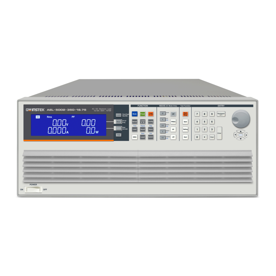
GETTING STARTED Appearance Front Panel Four meters can display the voltage value at the 1 LCD Multi- function same time Voltage(Vrms, Vpeak, Vmax, Vmin), display Current (Irms, Ipeak, Imax, Imin.) , Watt, Voltampere (VA), Frequency, Crest Factor, Power Factor, Total Harmonic Distortion of Voltage(VTHD), Voltage Harmonic (VH), Total Harmonic Distortion of Current (ITHD), Current Harmonic (IH) - Page 30 AEL-5000 User Manual These keys can select Short/OPP/OCP/Non- 5 Test function keys L/NL-CR/Fuse/Batt(Battery Discharge)Trans(UPS transfer time) test functions. 6 Number keypad 7 Knob setting 8 Power switch 9 Cursor and button setting...
-
Page 31: Lcd Display
GETTING STARTED LCD Display Refers to model number, voltage, current and 1 Model number power specification of AEL-5000 Series High and sink ranges Power AC/DC Electronic Load. When AEL-5000 Series AC/DC Electronic 2 REM LCD Load is connected with computer program for... - Page 32 AEL-5000 User Manual drops. If the Item buttons are pressed the left display Test mode will show a text Message that correlates with the selected test function. SHORT test selected: left display will show “Short”. OPP test selected: left display will show ...
- Page 33 NG indicator will illuminate. There are four operating modes. These can be 6 V/A/W key selected in turn by pressing the “V/A/W” key on the AEL-5000 Series AC/DC Electronic Load. The sequence is: Peak ...
- Page 34 AC/DC Electronic Load. The sequence There are four operating modes. These can be 9 THD Key selected in turn by pressing the “THD” key on the AEL-5000 Series AC/DC Electronic Load. The sequence is: V_THD I_THD ...
- Page 35 GETTING STARTED In V_H operating modes, these can be selected in turn by pressing the “PF/ CF/ FREQ” key and WATT/ VA/ VAR Key to adjust, the setting range is 01TH ~ 50TH.
- Page 36 AEL-5000 User Manual In I_H operating modes, these can be selected in turn by pressing the “PF/ CF/ FREQ” key and WATT/ VA/ VAR Key to adjust, the setting range is 01TH~ 50TH. The right 5 digit displays also changes function 10 Right lower 5 depending if the unit is in normal mode or one digit LCD...
- Page 37 GETTING STARTED If CP mode is selected the right display provides setting in watts “W”. If CV mode is selected the right display provides setting in volts “V”. LIMIT Each press of the LIMIT button changes the middle LCD text. The sequence and the corresponding setting value shown on the bottom display is as follows: V_Hi (left limit voltage) displays the set...
- Page 38 AEL-5000 User Manual value shown on the bottom displays are as follows: EXTIN can be set to “OFF” or “ON” SYNC can be set to “OFF” or “ON” LD ON LDOFF BW can be set to 1~15. ...
- Page 39 GETTING STARTED protection test to be set up. Each press of the Item button and Setting button moves the set function. The sequence of the OPP test along with the setting value is as follows: OPP Press Start (pressing the red ...
- Page 40 Similarly if OPP is shown on the display the over power protection has been activated. On the AEL-5000 Series AC/DC Electronic 11 Mode and Indicators Load, there are 5 working modes which can be...
-
Page 41: Function Description
FUNCTION DESCRIPTION UNCTION DESCRIPTION Function keys description ........40 Store or Recall functions ......... 56 Sequence Functions ..........57 Wave Function description ........61 Test Function description ........71 Entry key description ..........102... -
Page 42: Function Keys Description
(CV) Constant Voltage The appropriate LCD will illuminate according to the operating mode is selected. The input to the AEL-5000 Series AC/DC Load key and Load Electronic Load can be switched ON/OFF On/Off indicators by using the “LOAD” button. Indication of the ON/OFF state is provided by illumination of the button. - Page 43 A/B for rapid switching load current or resistance. The voltmeter and internal trigger circuit Sense key and of AEL-5000 series AC/DC electronic load Sense indicators can be controlled by this Key thus determining whether or not the input to the voltmeter Is made from the AC input terminal (OFF) or Vsense terminal (ON).
- Page 44 AEL-5000 User Manual Constant Current (CC) mode: The A and B levels of load current can be preset at right lower 5 digit LCD. The “A” LED will be lit indicating the setting value is amps. Linear Constant Current (LIN) mode: ...
- Page 45 FUNCTION DESCRIPTION the rotary knob and can be read from the right LCD during setting. The setting sequence is shown below: V_Hi (DVM upper limit) V_Lo (DVM lower limit) I_Hi (DAM upper limit) I_Lo (DAM lower limit) ...
- Page 46 AEL-5000 User Manual Setting upper limit voltage VH , the right upper 5 digit monitor display the ”V-Hi” and right lower monitor display upper limit of the voltmeter with the unit as “V” ,The V-Hi set range from 0.00 V to 600.00V step 0.01V by rotating the Setting knob.
- Page 47 FUNCTION DESCRIPTION Setting upper limit power WH, the right upper 5 digit monitor display ”W- Hi” and right lower monitor display upper limit of the voltmeter with the unit as “W”, The W-Hi set range from 0 W to 8000.0W step 1W by rotating the Setting knob.
- Page 48 AEL-5000 User Manual Setting lower limit power VAL, the right upper 5 digit monitor display ”VA-Lo” and right lower monitor display lower limit of the voltmeter with the unit as “W”, The VA-Lo set range from 0.0 VA to 8000.0VA step 0.1VA by rotating the Setting knob.
- Page 49 FUNCTION DESCRIPTION CC mode, press limits key to set the V- Hi and V-Lo voltage upper and lower Limit limits of the GO / NG. Current Load Current Voltage High CR mode, press limits key to set the V- ...
- Page 50 AEL-5000 User Manual The CONFIG key allows the sense Config key function to engage automatically or Config switched ON. The CONFIG key also enables the LOAD to automatically turn ON/OFF When a voltage level is reached. Each press of the CONFIG key moves the menu on one step.
- Page 51 FUNCTION DESCRIPTION The right upper 5 digit monitor display the EXTIN and right lower monitor display OFF or ON for external input disable or enable. Default is OFF The right upper 5 digit monitor display the SYNC and right lower monitor display OFF or ON for synchronous from external source disable or enable of rear panel I/O input terminal.
- Page 52 AEL-5000 User Manual The right upper 5 digit monitor display the LDOFF and right lower monitor display load off angle setting with the unit as “degree”. The range is 0 to 359 degree. The right upper 5 digit monitor display ...
- Page 53 FUNCTION DESCRIPTION The right upper 5 digit monitor display the CYCLE and right lower monitor display 1 for CYCLE value. The range is 1~16, Default is 1. The right upper 5 digit monitor display the SNUB and right lower monitor display “AUTO”...
- Page 54 5 digit monitor display setting GPIB address of the representative, Press UP, DOWN buttons to adjust the GPIB address 1~30, Key and then press ENTER, AEL-5000 series GPIB Address value is saved, Press system key four times to leave the GPIB address configuration State.
- Page 55 ”baud” and right lower monitor display setting BAUD-RATE value, Press UP, DOWN buttons to adjust the value of BAUD RATE, Key and then press ENTER, AEL-5000 Series is saved setting BAUD RATE, press system key three times to leave the BAUD-RATE setting state.
- Page 56 WAKE-UP function the load status and load level in turning System on The AEL-5000 Series every time. SYSTEM key first by the three. The Left 5 digit monitor display the “WAKE”, the right upper 5 digit monitor display the ”UP”, and right lower monitor display setting value, Press UP, DOWN buttons to adjust the 0~150.
- Page 57 FUNCTION DESCRIPTION Note Setting system parameters, if the input is required to use the KEYPAD ENTER button to confirm, otherwise AEL- 5000 Series will not save the changes the settings. Pass: Automatic test mode, no NG state, is the PASS. Fail: Automatic test mode, any test if the NG then is the FAIL.
-
Page 58: Store Or Recall Functions
AEL-5000 User Manual Store or Recall functions The function keys on the front panel of AEL-5000 Series mainframe are designed for high testing throughput purpose. There are 150 operation states or testing steps can be store in the EEPROM memory of AEL-5000 Series electronic load respectively, each state can store or recall the load status and level for Electronic load simultaneously. -
Page 59: Sequence Functions
FUNCTION DESCRIPTION Sequence Functions Press SEQ key to enter SEQ setting mode, SEQ key LED indicator ON, the setting sequence is as follows: Use UP and DOWN keys to set EDIT F1 or TEST F1 mode, if you want to leave SYSTEM (Exit) Press SHIFT key, press the SEQ. - Page 60 AEL-5000 User Manual Test time setting Press ENTER to set TIME value, press UP, DOWN keys or KEYPAD to adjust settings, range from 100 ms~9999ms. Press SAVE key to finish editing the action is set to REPEAT, If you do not save the settings, press the EXIT key to leave edit mode.
- Page 61 FUNCTION DESCRIPTION Press the SHIFT and SEQ key Test mode simultaneously to enter the AUTO SEQUENCE Mode, and press UP or DOWN key to TEST function, To use the key pad to setting 1~9 for F1 to F9 and press ENTER key to execute the automatic test mode.
- Page 62 AEL-5000 User Manual Test mode operation flow chart...
-
Page 63: Wave Function Description
FUNCTION DESCRIPTION Wave Function description CF key only functions upon C.C. and C.P. C F k e y a n d mode and all LED off upon Linear C.C., √2, 2, 2.5, 3, C.R. and C.V. mode. √2, 2, 2.5, 3, 3.5 keys 3.5 keys are used to quick change the current C.F. - Page 64 AEL-5000 User Manual Press the CF key, and √2 key settings will be automatically saved and exit. Press the CF key, and 2 key settings will be automatically saved and exit. Press the CF key, and 2.5 key settings will be automatically saved and exit.
- Page 65 Note CF( crest factor) range 1.4142 ~ 5.0, AEL-5000 Series full scale current is 3 times the peak, if use the CF peak 5.0, AEL-5000 scale current so the current must be reduced to 45A, in order to reach the peak 5.0.
- Page 66 AEL-5000 User Manual 90 degree SCR Leading edge current waveform Positive half-cycle or negative half-cycle load setting use the knob and key to adjust the CF value, or press the CF key, the Keypad key enters 1.1 (LDNEG), the monitor displays LDNEG is negative half-cycle loading, the Keypad key enters 1.0 (LDPOS),LDPOS for positive half-cycle loading.
- Page 67 FUNCTION DESCRIPTION (PF is 0.75) (CF is 1.9) (CF set to 1.8, and the adjustable range of PF is 0.8~0.9) (PF changed to 0.80) FREQ key only functions upon C.C. and FREQ key and C.P. mode and all LED off upon Linear Auto, DC, FREQ 50Hz, 60Hz...
- Page 68 AEL-5000 User Manual Press the FREQ key and 50Hz key settings will be automatically saved and exit. FREQ Press the FREQ key and 60Hz key settings will be automatically saved and exit. FREQ Press the FREQ key and 400Hz key settings will be automatically saved and FREQ exit.
- Page 69 FUNCTION DESCRIPTION PF (lead) key only functions upon C.C. PF key and 1, and C.P. mode and all LED off upon 0.9, 0.8, 0.7, 0.6 keys Linear C.C., C.R. and C.V. mode. 1, 0.9, 0.8, 0.7 and 0.6 keys are used to quick change the P.F.
- Page 70 AEL-5000 User Manual Press the PF key, setting range from 0.01 to 1.00, step 0.01 by rotating the Setting knob, press the ENTER key after the completion of the setting will be automatically stored. Adjustment of PF The adjustable range of PF will be different due to CF.
- Page 71 FUNCTION DESCRIPTION PF (lag) key only functions upon C.C. and -PF key and 1, C.P. mode and all LED off upon Linear 0.9, 0.8, 0.7, 0.6 keys C.C., C.R. and C.V. mode. 1, 0.9, 0.8, 0.7 and 0.6 keys are used to quick change the P.F.
- Page 72 AEL-5000 User Manual Press the -PF key, setting range from- 0.01 to -1.00, step 0.01 by rotating the Setting knob, press the ENTER key after the completion of the setting will be automatically stored. PF setting range, when CF is set to 2, the PF setting range is 0.55~0.8.
-
Page 73: Test Function Description
Item, Setting and Exit key for Test. There Item, Setting are ten operating modes. These can be and Exit keys Item selected in turn by pressing the “Item “key on the AEL-5000 series AC/DC Electronic Load module. The sequence is: Setting SHORT ... - Page 74 AEL-5000 User Manual The SHORT test will attempt to sink high The SHORT current up to the AEL-5000 Series AC/DC parameters setting load maximum current in order to check the power source’s protection and behavior. The test time can be adjusted and threshold values for the High and low voltage limits set.
- Page 75 FUNCTION DESCRIPTION Each press of the Setting key moves the menu on one step. The left and right LCDs Setting show the currently selected test parameter as text. The value is adjusted by the rotary knob and can be read from the right display during setting.
- Page 76 AEL-5000 User Manual SHORT TIME: setting the Short test time, the left 5 digit monitor display the “SHORT”, the right upper 5 digit monitor display the TIME and right lower monitor display “100ms” , the range is 100ms to 10000ms. The short test will be no time limitation when setting to CONTI until press “START/STOP”...
- Page 77 FUNCTION DESCRIPTION Once the test parameters have been Start entered the test is started by pressing the Stop red START/STOP button while the SHORT PRESS START text is displayed. During the test the bottom LCD will show run and the actual short current will be displayed on the right upper LCD.
- Page 78 AEL-5000 User Manual Each press of the Setting button moves the menu on one step. The Left and Middle Setting LCDs show the currently selected test parameter as text. The value is adjusted by the rotary knob and can be read from the Right display during setting.
- Page 79 FUNCTION DESCRIPTION PSTAR: setting the start power, the Left 5 digit monitor display the “OPP” ,the right upper 5 digit monitor display the “PSTAR”, and right lower monitor display setting value, the unit is “W”. The range is 0.1W to the full scale of the CP mode specification.
- Page 80 AEL-5000 User Manual Vth : Setting threshold voltage; the Left 5 digit monitor display the “OPP” ,the right upper 5 digit monitor display the “VTH”, and right lower monitor display setting value, the unit is “V”. The range is 0.01V to the full scale of the Voltage specification.
- Page 81 FUNCTION DESCRIPTION Each press of the setting button moves the menu on one step. The Left and right Setting LCDs show the currently selected test parameter as text. The value is adjusted by the rotary knob and can be read from the Right display during setting.
- Page 82 AEL-5000 User Manual scale of the CC mode specification. ISTEP: setting the increment step current point, the Left 5 digit monitor display the “OCP” ,the right upper 5 digit monitor display the “ISTEP”, and right lower monitor display setting value, the unit is “A”.
- Page 83 FUNCTION DESCRIPTION Once the test parameters have been Start entered the test is started by pressing the Stop red START/STOP button while the OCP PRESS START text is displayed. During the Test the middle LCD will show run and the actual current being Taken will be displayed on the Right LCD Note The message OCP ERROR will be displayed if the DUT...
- Page 84 AEL-5000 User Manual Non-L PF Non-L CC: setting the Non-L current point, the Left 5 digit monitor display the “Non-L” ,the right upper 5 digit monitor display the “CC”, and right lower monitor display setting value, the unit is “A”. The range is 0.001A to the full scale of the CC mode specification.
- Page 85 FUNCTION DESCRIPTION Each press of the setting button moves the menu on one step. The Left and right Setting LCDs show the currently selected test parameter as text. The value is adjusted by the rotary knob and can be read from the Right display during setting.
- Page 86 AEL-5000 User Manual Pressing the Item key once will cause the The FUSE button to illuminate. The message “FUSE parameters Item setting PRESS START” will be shown across the displays. Each press of the Setting button moves the menu on one step. The Left and right Setting LCDs show the currently selected test parameter as text.
- Page 87 FUNCTION DESCRIPTION FUSE CC : setting the fuse current point, the Left 5 digit monitor display the “FUSE” ,the right upper 5 digit monitor display the “CC”, and right lower monitor display setting value, the unit is “A”. The range is 0.001A to the full scale of the CC mode specification.
- Page 88 AEL-5000 User Manual Pressing the Item key once will cause the The BATT button to illuminate. The message “BATT parameters Item setting PRESS START” will be shown across the displays. Each press of the setting button moves the menu on one step. The Left and right Setting LCDs show the currently selected test parameter as text.
- Page 89 FUNCTION DESCRIPTION The Left 5 digit monitor display the “BATT” ,the right upper 5 digit monitor Display the “MODE”, and right lower monitor display the “CC”, use the knob and the key to switch CC, LIN, CR or BATT CC : setting the battery current ...
- Page 90 AEL-5000 User Manual The left 5 digit monitor display the “BATT”, the right upper 5 digit monitor display the “PF”, and right lower monitor display the ”LEAD”, use the knob and the key to LEAD or LAG. BATT CF: setting the PF, the Left 5 digit ...
- Page 91 FUNCTION DESCRIPTION BATT TIME: setting the battery test time, the Left 5 digit monitor display the “BATT”, the right upper 5 digit monitor display the “TIME”, and right lower monitor display setting value, the unit is “S”. The range is 1S ~99999S. BATT VTH: the Left 5 digit monitor ...
- Page 92 AEL-5000 User Manual BATT LIN : setting the BATT LIN, the Left 5 digit monitor display the “BATT” ,the right upper 5 digit monitor display the “LIN”, and right lower monitor display setting value, the unit is “A”. The range is 0.001A to the full scale of the CC mode specification.
- Page 93 FUNCTION DESCRIPTION Press the Item key to enter the Item setting mode BATT PRESS START, the Item LED indicators is ON, and then press the setting key. The LED indicator is ON. To exit the setting, press the EXIT key and Setting select CR MODE.
- Page 94 AEL-5000 User Manual BATT TIME: setting the BATT TIME, the Left 5 digit monitor display the “BATT” ,the right upper 5 digit monitor display the “TIME”, and right lower monitor display setting value, the unit is “S”. The range is 1s to the 99999s. BATT Vth: Setting BATT threshold ...
- Page 95 FUNCTION DESCRIPTION BATT CP: setting the BATT CP, the Left 5 digit monitor display the “BATT” ,the right upper 5 digit monitor display the “CP”, and right lower monitor display setting value, the unit is “W”. The range is 0.1W to the full scale of the CP mode specification.
- Page 96 AEL-5000 User Manual cycle loading BATT CF: setting the PF, the Left 5 digit monitor display the “BATT” ,the right upper 5 digit monitor display the “PF”, and right lower monitor display setting value. The range is 0.01 ~1.00. BATT TIME: setting the Battery test ...
- Page 97 FUNCTION DESCRIPTION BATT VTH: the Left 5 digit monitor display the “BATT” ,the right upper 5 digit monitor display the “VTH”, and right lower monitor display setting value, the unit is “V”. The range is 0.01V to the full scale of the Voltage specification.
- Page 98 AEL-5000 User Manual Pressing the Item key once will cause the The INRUS button to illuminate. The message parameters Item setting “INRUS PRESS START” will be shown across the displays. Each press of the setting button moves the menu on one step. The Left and right Setting LCDs show the currently selected test parameter as text.
- Page 99 FUNCTION DESCRIPTION INRUS FREQ: setting the INRUS FREQ, the Left 5 digit monitor display the “INRUS”, the right upper 5 digit monitor display the “FREQ”, and Right lower monitor display setting value, the unit is "Hz”, use the knob and button to set the Range from DC and 40~ 440Hz.
- Page 100 AEL-5000 User Manual INRUS TIME : setting the INRUS TIME, the Left 5 digit monitor display the “INRUS”, the right upper 5 digit monitor display the “TIME”, and right lower monitor display setting value, the unit is “ms”. Use the knob and button to set the time, the setting range from 0.1ms to the 100.0ms.
- Page 101 FUNCTION DESCRIPTION SURGE S2 SURGE T2 SURGE S3 SURGE T3 SURGE FREQ: setting the SURGE FREQ, the Left 5 digit monitor display the “SURGE”, the right upper 5 digit monitor display the “FREQ”, and Right lower monitor display setting value, the unit is “Hz”, use the knob and button to set the Frequency value, the setting...
- Page 102 AEL-5000 User Manual SURGE T1: setting the SURGE T1, the Left 5 digit monitor display the “SURGE” ,the right upper 5 digit monitor display the “T1”, and right lower monitor display setting value, the unit is “S”, use the knob and button to set the first surge current time value, the setting range from 0.01s to the 0.50s.
- Page 103 FUNCTION DESCRIPTION SURGE S3: setting the SURGE S3, the Left 5 digit monitor display the “SURGE”, the right upper 5 digit monitor display the “S3”, and right lower monitor display setting value, the unit is “A”, use the knob and button to set the Third surge current value, the setting range from 0.000A to the 75.000A.
-
Page 104: Entry Key Description
AEL-5000 User Manual Entry key description The ROTARY knob and ARROW keys are used to Rotary Knob and increase or decrease the set values. ARROW Keys Clockwise the rotary switch and UP arrow key to increase the setting values. Anti-clockwise the rotary switch ... - Page 105 FUNCTION DESCRIPTION Note In CR mode, increase setting value define for current value, so clockwise the rotary switch and press UP key will decrease the resistance value to increase the current value. Anti-clockwise the rotary switch and press DOWN key will increase the resistance value to decrease the current value.
-
Page 106: Connection
AEL-5000 User Manual ONNECTION Rear Panel ............. 105 Connecting the I-monitor to an oscilloscope ..109 Master/Slave Description ........110 2 operating modes for Master/Slave ...... 112 Boost mode ................112 3PH mode ................113 REMOTE operating ..........117... -
Page 107: Rear Panel
Communication interface (GPIB, RS-232, USB, LAN) When Load Input Connector is used, be sure that AC/DC INPUT the rated specification of the voltage and current Terminal of the AEL-5000 Series AC/DC Electronic Load shall not be exceeded. - Page 108 CONNECTOR REPLACE FUSE AS SPECIFIED DISCONNECT POWER CORD BEFORE REPLACING FUSE 100 240V 47 63Hz 390VA MAX. AEL-5000 Series FUSE T 4A 250V RATING load module SENSE AC / DC INPUT TO AVOID ELECTRIC SHOCK THE POWER CORD PROTECTIVE SER. NO. LB GROUNDING CONDUCTOR MUST BE CONNECTED TO GROUND.
- Page 109 AEL-5008-350-75: Imax = 75A therefore I-monitor Example 10V = 75A so 1V = 7.5A Please refer to the specification paragrph for the maximum current that each AEL-5000 series load is capable of. The current monitor of this unit is NOT isolated. CAUTION Please be careful when you connect an oscilloscope.
- Page 110 AEL-5000 User Manual The AEL-5000 series Load will attempt to load proportionally according to the signal and the load module’s maximum current or power range. For example: AEL-5008-350-75: Imax = 75A and Pmax =7500W So in CC mode if analogue programming input is 5V = 37.5A load setting or in CP mode if analogue...
-
Page 111: Connecting The I-Monitor To An Oscilloscope
CONNECTION Connecting the I-monitor to an oscilloscope When you connect this product to an oscilloscope, please ensure the correct polarities of the connecting probes as shown in fig below AEL-5000 series (Correct) Connections to an oscilloscope AEL-5000 series (Wrong) Connections to... -
Page 112: Master/Slave Description
AEL-5000 User Manual Master/Slave Description AEL-5000 Series “MASTER / SLAVE” Parallel Background function, 1 Master, 7 SLAVE, setting method press the System key to set the CONTROL MODE to select ALONE, MASTER or SLAVE1 ~ 7, Press the ENTER key to set, when Power off Data will not be lost, this parameter is saved. - Page 113 CONNECTION...
-
Page 114: Operating Modes For Master/Slave
AEL-5000 User Manual 2 operating modes for Master/Slave Boost mode Boost mode is for master / slave parallel application, the setting current will be actively shared to each load, Master ammeter will show the total current that is the sum of all ammeters, Slave voltmeter will show SL1 ~ SL2, the others are unchanged. -
Page 115: 3Ph Mode
CONNECTION 3PH mode 3PH mode is for 3 phase application, three AEL- 5000 Series can be connected for three phase Δ or Y connection, the setting current value (single- phase current value) will be sent to each Slave unit automatically, the user does not have to set each unit. - Page 116 AEL-5000 User Manual CC is set to 60A Master 3phase Display Slave 1 Display Slave 2 Display LIN is set to 60A Master 3phase Display Slave 1 Display Slave 2 Display CR is set to Master 3phase 1.8333Ω Display Slave 1 Display Slave 2 Display CP is set to Master 3phase...
- Page 117 CONNECTION Slave 2 Display CV is set to 110V Master 3phase Display Slave 1 Display Slave 2 Display Master boost (AEL-5008-350-75 MASTER boost/SLAVE model Manual operation the following is example) PRESET Setting: CC/LIN/CR/CV/CP Mode as Figure, CC setting 180A=Master 60A + Slave 1 60A+ Slave 2 60A, LIN setting 180A=Master 180A + Slave 1 60A+ Slave2 60A, CR: 800Ω...
- Page 118 AEL-5000 User Manual LIN is set to 180A Master booster Display Slave 1 Display Slave 2 Display CR is set to Master booster 2400Ω Display Slave 1 Display Slave 2 Display CP is set to Master booster 22500W Display Slave 1 Display Slave 2 Display Note Master Mode operation except CC /LIN / CR / CV /...
-
Page 119: Remote Operating
CONNECTION REMOTE operating Master Mode can use the command as follows SETTING PRESET NUMERIC COMMAND REMARK MODE {SP} {CC|LIN|CR|CV|CP} {;|NL} OCLSP NR2 ;|NL OPLSP NR2 ;|NL SENS {SP} {ON|OFF|1|0} {;|NL} 0:OFF, 1:ON ON:ANGSP NR2 ;|NL OFF:ANGSP NR2 ;|NL CC|CURR:A|B SP NR2;|NL LIN:A|B... - Page 120 AEL-5000 User Manual 1~50;select HARM {SP} {NR1} {;|NL} Harmonic step SYNC {SP}{ON|OFF} {;|NL} MEAS:TYPE{SP} {RMS|PEAK|MAX|MIN} {;|NL} RS232/USB/LAN REMOTE {;|NL} command RS232/USB/LAN LOCAL{;|NL} command AUTO SEQUENCE 3PH MODE can’t be used command AUTO SEQUENCE Set the NOTE RETURN command FILE {SP} {n}{;|NL} n=1~9 STEP {SP} {n} {;|NL} n=1~32...
- Page 121 CONNECTION GLOB: MEAS: VA {?}{;|NL} #####.#,#####.#,#####.#, GLOB: MEAS: V_THD {?}{;NL} ###.##,###.##,###.##, GLOB: MEAS: I_THD {?}{;|NL} ###.##,###.##,###.##, GLOB: MEAS: V_HARM {?}{;|NL} ###.##,###.##,###.##, GLOB: MEAS: I_HARM {?}{;|NL} ###.###,###.###,###.###, GLOB: MEAS: PF {?}{;|NL} ###.##,###.##,###.##, GLOB: MEAS: CF {?}{;|NL} ####.#,####.#,####.#, GLOB: MEAS: FREQ {?}{;|NL} ####.#,####.#,####.#,...
-
Page 122: Installation
AEL-5000 User Manual NSTALLATION Check line voltage ..........121 Grounding requirements ........122 Power up ............... 123 Connection to the load Input Terminal ....124 Interface Card ............125 GPIB & RS232 interface option .......... 125 RS232 interface option ........... 126 GPIB interface option .......... -
Page 123: Check Line Voltage
INSTALLATION Check line voltage Background The AEL-5000 Series high power AC/DC load can operation with 100 Vac ~240Vac input as indicated on the label on the rear panel. Make sure that the factory check mark corresponds to your nominal line voltage. Skip this procedure if the label is corrected marked. -
Page 124: Grounding Requirements
AEL-5000 User Manual Grounding requirements Installation It is requested to use the 3Pin plug connector only for AEL-5000 Series mainframe to out of danger when electric leakage. And the complete and proper grounded is necessary. The AEL-5000 Series high power AC/DC load... -
Page 125: Power Up
INSTALLATION Power up The following procedure should be followed before applying mains power: Procedure 1. Turn off (O) the POWER switch. 2. Check that the power cord is corrected. 3. Check that nothing is connected to the DC INPUT on the rear panels. 4. -
Page 126: Connection To The Load Input Terminal
AEL-5000 User Manual Connection to the load Input Terminal Connection procedure of the load input terminal on the rear panel Procedure 1. Turn off POWER switch. 2. Check that the output of the equipment under test is off. 3. Connect the load wire to the load input terminal on the rear panel. -
Page 127: Interface Card
Connection procedure of the load input terminal on the rear panel Procedure 1. GPIB + RS232 interface is on the rear panel of AEL-5000 Series Mainframe for application GPIB or RS232 . 2. GPIB and RS232 interface can only be used at the same time, to Change the interface must reboot unit. -
Page 128: Rs232 Interface Option
Series mainframe to RS232 port of computer in one by one configuration. The RS232 BAUD-RATE can be set in the front panel, it will be lit the GPIB address when press the “SYSTEM” button. Press it again, it will be lit the BAUD-RATE. AEL-5000 Series RS232 interface... -
Page 129: Gpib Interface Option
GPIB interface USB interface option Connection procedure of the load input terminal on the rear panel The figure below shows the USB connector in the rear panel of AEL-5000 Series mainframe. AEL-5000 USB interface Note Please refer Appendix on page 249 for details about USB instruction. -
Page 130: I/O Connection
Please refer Appendix on page 255 for details about LAN instruction. I/O connection Connection procedure of the load input terminal on the rear panel AEL-5000 Series I/O Interface with I monitor, V- monitor, Analog Programming Input, SYNC input AEL-5000 Series I/O Connection... -
Page 131: Load Wire Inductance
This voltage applies to all of the load input terminals of the AEL-5000 Series when the impedance of the EUT is relatively small. The voltage generated by the load wire inductance (L) and the current variation (I) is expressed using the following equation. - Page 132 In such event, the electronic load (AEL-5008- 350-75) may generate unstable oscillation. In such condition, the input voltage may exceed the maximum input voltage and Cause damage to the AEL-5000 series.
- Page 133 INSTALLATION Waveform example: Generate unstable oscillation CH1= Imonitor CH2=Power Supply output Voltage (x10) CH3= LOAD Input Voltage (x10)
- Page 134 In the case of DC operation also, the phase delay of the current may cause instability in the AEL-5000 series Control inducing oscillation. In this case also, connect the AEL- 5000 series and the equipment under test using the shortest twisted wire possible.
-
Page 135: Parallel And Three-Phase Control
INSTALLATION Parallel and three-phase control 3 phase Y connection 3 phase △ connection GPIB, RS-232, USB, LAN or Manual Master Slave 1 Slave2 Parallel connection GPIB, RS-232, USB or LAN GPIB, RS-232, USB, LAN or Manual Master Slave 1 Slave2... -
Page 136: Remote Control
AEL-5000 User Manual EMOTE CONTROL The rear panel remote control interface of AEL-5000 Series mainframe is designed to connect PC or NOTEBOOK PC with remote control interface, the NOTEBOOK PC acts as a remote controller of AEL-5000 Series Electronic Load. -
Page 137: Interface Configuration
REMOTE CONTROL Interface Configuration Configure RS232C The following RS232 commands are same as GPIB commands. The RS232 protocol in AEL-5000 Series mainframe is listing below: Baud Rate 9600~115200bps RS232C Configuration Stop Bit 1 bit Data Bit 8 bits Parity None... - Page 138 AEL-5000 User Manual Pin Assignment Abbreviation Description Pin1 Carrier Detect Pin2 Receive Pin3 Transmit Pin4 Data Terminal Ready Pin5 Ground Pin6 Data Set Ready Pin7 Request To Send Pin8 Clear To Send Pin9 Ring Indicator...
-
Page 139: Communication Interface Programming Command List
REMOTE CONTROL Communication Interface programming command list SIMPLE TYPE FORMAT Table: Communication interface programming setting command summary SETTING PRESET NUMERIC COMMAND Note HARMSP NR1 ;|NL HARMONICS 1~50 LIN:A|B SP NR2;|NL CC|CURR:A|B SP NR2;|NL CP:A|B SP NR2;|NL CR|RES:A|B SP NR2;|NL CV|VOLT:A|B SP NR2;|NL CVI:A|B... - Page 140 AEL-5000 User Manual FUSE:TYPE {SP} {TRIP|NTRIP}{;|NL} FUSE:REP {SP} {NR1}{;|NL} AVG{SP} {NR2}{;|NL} NR2:1|2|4|8|16 CPRSP{SP} {NR2}{;|NL}{;|NL} NR2:0~7 CYCLE{SP} {NR2}{;|NL} NR2:1~16 ON:ANG{SP} {NR2}{;|NL} 0~359 OFF:ANG{SP} {NR2}{;|NL} 0~359 BW {SP} {NR2}{;|NL} FREQ {SP} {AUTO| NR2}{;|NL} 0,40~440Hz ITIME {SP} {NR2}{;|NL} 0.1ms~100.0ms ISTART {SP} {NR2}{;|NL} ISTEP {SP} {NR2}{;|NL} ISTOP{SP} {NR2}{;|NL} SURGE:Tn{SP} {NR2}{;|NL} SURGE:Sn{SP} {NR2}{;|NL}...
- Page 141 REMOTE CONTROL OPP: STOP{?}{;|NL} #####.# STIME{?}{;|NL} ##### PF {?}{;|NL} ###.## CF {?}{NR2}{;|NL} ####.# OCP{?}{;|NL} ###.### OPP{?}{;|NL} #####.# BATT:MODE {?}{;|NL} 0~3=CC/LIN/CR/CP BATT:TIME {?}{;|NL} ##### DISC:TIME {?}{;|NL} DISC:AH {?}{;|NL} EXTIN{?}{;|NL} TURBO{?}{;|NL} FUSE:CC {?}{;|NL} ###.### FUSE:TIME {?}{;|NL} ####.# FUSE:TYPE {?}{;|NL} FUSE:REP {?}{;|NL} 0~255 TRIP:TIME {?}{;|NL} ####.# TRANS:TIME {?}{;|NL}...
- Page 142 AEL-5000 User Manual Table: Communication Interface programming limit command summary LIMIT COMMAND RETURN IH|IL{SP}{NR2}{;|NL IH|IL {?}{;|NL ###.### WH|WL{SP}{NR2}{;|NL WH|WL {?}{;|NL #####.# VH|VL{SP}{NR2}{;|NL VH|VL {?}{;|NL ###.## SVH|SVL{SP}{NR2}{;|NL SVH|SVL {?}{;|NL ###.## VAH|VAL{SP}{NR2}{;|NL VAH|VAL {?}{;|NL #####.# OPL|OCL{SP}{NR2}{;|NL Over power limit/Over current limit OPL|OCL {?}{;|NL #####.# / ###.### Table: STAGE COMMAND SUMMARY STAGE COMMAND...
-
Page 143: System Command
REMOTE CONTROL NG {?}{;|NL} 0:GO 1:NG PROT {?}{;|NL} NGENABLE{SP}{ON|OFF}{;|NL} START{;|NL} STOP{;|NL} TESTING {?}{;|NL} 0:TEST END,1:TESTING SYNC {SP}{ON|OFF|1|0} {;|NL} SYNC {?} {;|NL} 0:OFF 1:ON System command Table: SYSTEM COMMAND SUMMARY COMMAND NOTE RETURN RECALL {SP} {m }{;|NL} m=1~150 , m:STATE STORE {SP} {m }{;|NL} m=1~150 m:STATE RS232/USB/LAN REMOTE {;|NL}... -
Page 144: Auto Sequence
AEL-5000 User Manual Remark 1. Current engineering unit: A/Arms 2. Resistance engineering unit: Ω 3. Voltage engineering unit: V/Vrms 4. Period engineering unit: mS 5. Frequency engineering unit: Hz. 6. Power engineering unit: W 7. Volt-Ampere engineering unit: VA AUTO SEQUENCE Table: Auto sequence command list AUTO SEQUENCE SET NOTE... - Page 145 REMOTE CONTROL PRESet: CV|VOLT:A|B SP NR2;|NL PRESet: CVI:A|B SP NR2;|NL [PRESet:] TCONFIG {SP} {NORMAL|OCP | OPP | SHORT|NLIN|NLCR|FUSE|BATT|TRANS |INRUSH|SURGE }{;|NL} [PRESet:]OCP:START {SP} {NR2}{;|NL} [PRESet:]OCP:STEP {SP} {NR2}{;|NL} [PRESet:]OCP:STOP {SP} {NR2}{;|NL} [PRESet:]VTH {SP} {NR2}{;|NL} [PRESet:]OPP:START {SP} {NR2}{;|NL} [PRESet:]OPP:STEP {SP} {NR2}{;|NL} [PRESet:]OPP:STOP {SP} {NR2}{;|NL} [PRESet:]STIME {SP} {NR2}{;|NL} [PRESet:]PF {SP} {+|-} {NR2}{;|NL} Power factor...
- Page 146 AEL-5000 User Manual Table: Communication Interface programming query command summary QUERY COMMAND SUMMARY RETURN PRESet:HARMonics?;|NL PRESet:LIN:A|B?;|NL ###.### PRESet:CC|CURR:A|B ? ;|NL ###.### PRESet:CP:A|B ? ;|NL #####.# PRESet:CR|RES:A|B ? ;|NL #####.#### PRESet:CV|VOLT:A|B ? ;|NL ###.## 1:NORMAL 7:FUSE 2:SHORT 8:BATT 3:OPP 9:Trans [PRESet:] TCONFIG {?}{;|NL} 4:OCP 10:INRUSH 5: non-LIN 11:SURGE...
- Page 147 REMOTE CONTROL [PRESet:]TRANS: TIME {?}{;|NL} [PRESet:]AVG {?}{;|NL} 1|2|4|8|16 [PRESet:]CPRSP {?}{;|NL} [PRESet:]CYCLE {?}{;|NL} 1~16 [PRESet:]ON: ANG {?}{;|NL} ##### [PRESet:]OFF: ANG {?}{;|NL} ##### [PRESet:]REP: COUNT {?}{;|NL} ##### [PRESet:]BW {?}{;|NL} 1~15 [PRESet:]FREQ {?}{;|NL} ###.# [PRESet:]ITIME {?}{;|NL} ####.# [PRESet:]ISTART {?}{;|NL} ###.### [PRESet:]ISTEP {?}{;|NL} ###.### [PRESet:]ISTOP {?}{;|NL} ###.### [PRESet:]SURGE: Tn{?}{;|NL}...
- Page 148 AEL-5000 User Manual current limit OPL|OCL {?}{;|NL #####.# / ###.### Table: STAGE COMMAND SUMMARY STAGE COMMAND REMARK [STATe:] LOAD {SP}{ON|OFF} {;|NL} [STATe:] LOAD {?} {;|NL} 0:OFF 1:ON [STATe:] MODE {SP} {CC|LIN|CR|CV|CP} {;|NL} [STATe:] MODE {?} {;|NL} 0|1|2|3|4:CC|LIN|CR|CV|CP [STATe:] SHORt {SP} {ON|OFF} {;|NL} [STATe:] SHORt {?} {;|NL} 0:OFF 1:ON [STATe:] PRESet {SP} {ON|OFF} {;|NL}...
- Page 149 REMOTE CONTROL Table: SYSTEM COMMAND SUMMARY COMMAND NOTE RETURN [SYStem:]RECall {SP} {m }{;|NL} m=1~150 [SYStem:]STORe {SP} {m }{;|NL} m=1~150 RS232/USB/LAN [SYStem:]REMOTE {;|NL} command RS232/USB/LAN [SYStem:]LOCAL{;|NL} command [SYStem:]NAME {?} {;|NL} “XXXXX” Table: MEASURE COMMAND SUMMARY COMMAND RETURN MEASure:TYPE{SP} {RMS|PEAK|MAX|MIN} {;| NL} MEASure:CURRent {?}{;|NL} ###.### MEASure: VOLTage {?}{;|NL}...
-
Page 150: Command Syntax
AEL-5000 User Manual Command Syntax The description of abbreviation SP: Space, the ASCII code is 20 Hexadecimal. Command Tree ;:Semicolon, Program line terminator, the ASCII code is OA Hexadecimal. NL:New line, Program line terminator, the ASCII code is OA Hexadecimal. NR2:Digits with decimal point. - Page 151 REMOTE CONTROL This symbol means option. For example “LOW|HIGH”means it can only use LOW or HIGH as the command, it can choose only one as the setting command. Terminator: You have to send the program line terminator character after send the GPIB command, the available command terminator characters which can be accepted in AEL-5000 Series mainframe is listed in table below...
-
Page 152: Command List
AEL-5000 User Manual Command List PRESET Commands ..........152 HARM ..................152 LIN ....................152 ON:ANG ..................152 OFF:ANG .................. 152 CC|CURR:A|B ................. 153 CP:A|B ..................153 CR|RES:A|B ................153 CV|VOLT:A|B................. 154 CVI|VOLT:A|B ............... 154 TCONFIG .................. 154 ITIME ..................155 ISTART .................. - Page 153 REMOTE CONTROL CYCLE ..................163 BW ....................163 FREQ ..................163 REP:COUNT................164 Limit Commands ..........165 [LIMit:]CURRent:{HIGH|LOW} or IH|IL ...... 165 [LIMit:]POWer:{HIGH|LOW} or WH|WL ..... 165 [LIMit:]VOLtage:{HIGH|LOW} or VH|VL ....166 SVH|SVL ................... 166 STATE commands ..........167 [STATe:]LOAD{SP}{ON|OFF} ......... 167 [STATe:]MODE{SP}{CC|CR|CV|CP} ......
-
Page 154: Preset Commands
AEL-5000 User Manual PRESET Commands Set and Read the Default of Load HARM Query Set and read the HARMONICS Description Syntax [PRESet:]HARM{SP}{NR1}{;|NL} Query Syntax [PRESet:]HARM{?}{;|NL} Parameter <NR1> HARMONICS 1~50 1~50 Query Set and read the linear current. Description Syntax [PRESet:]LIN:A|B{SP}{NR2}{;|NL} Query Syntax [PRESet:]LIN:A|B{?}{;|NL} ON:ANG... -
Page 155: Cc|Curr:a|B
REMOTE CONTROL Syntax [PRESet:]OFF:ANG {SP}{NR2}{;|NL} Query Syntax [PRESet:]OFF: ANG{?}{;|NL} Parameter <NR1> 0~359 CC|CURR:A|B Query Set and read the current of A or B. This command Description is for setting the required Load current. And this command must be followed the next notices: Level A load and Level B load current settings are independent. -
Page 156: Cv|Volt:a|B
AEL-5000 User Manual CV|VOLT:A|B Query Set and read the value of voltage. This command Description is for setting the required value of voltage, and the unit is V. Syntax [PRESet:]CV:{A|B}{SP}{NR2}{;|NL} [PRESet:]VOLT:{A|B}{SP}{NR2}{;|NL} Query Syntax [PRESet:]CV:{A|B}{?}{;NL} [PRESet:]VOLT:{A|B}{?}{;NL} CVI|VOLT:A|B Query Set and read the value of voltage. This command Description is for setting the required value of voltage, and the unit is V. -
Page 157: Itime
REMOTE CONTROL non-LIN nocLIN+CR FUSE BATT Trans INRUSH SURGE ITIME Query Set and read the INRUSH current time. Use this Description command to set the interval for current decrement. The setting range is 0.1ms~100.0ms. Syntax [PRESet:]TIME{SP}{NR2}{;|NL} Query Syntax [PRESet:]ITIME{?} Parameter <NR2>... -
Page 158: Istop
AEL-5000 User Manual Syntax [PRESet:]ISTEP{SP}{NR2}{;|NL} Query Syntax [PRESet:]ISTEP{?} ISTOP Query Set and read the set value of the minimum current Description for the inrush current test. Minimum current setting range current specification. Syntax [PRESet:]ISTOP{SP}{NR2}{;|NL} Query Syntax [PRESet:]ISTOP{?} SURGE:Tn Query Set and read the time setting for the surge current Description test. -
Page 159: Ocp:start
REMOTE CONTROL OCP:START Query Set and read the initial value of OCP test. This Description command is used for setting the required initial value (I-START) of OCP Syntax [PRESet:]OCP:START{SP}{NR2}{;|NL} Query Syntax [PRESet:]OCP:START{?}{;|NL} OCP:STEP Query Set and read the increasing value of OCP test. This Description command is used for setting the increasing value (I-STEP) of OCP test. -
Page 160: Opp:start
AEL-5000 User Manual OPP:START Query Set and read the initial value of OPP test. This Description command is used for setting the required initial value (P-START) of OPP Syntax [PRESet:]VTH{SP}{NR2}{;|NL} Query Syntax [PRESet:]VTH{?}{;|NL} OPP:START Query Set and read the increasing value of OPP test. This Description command is used for setting the increasing value (P-STEP) of OPP test. -
Page 161: Batt:mode
REMOTE CONTROL Query Set and read power factor. This command is set Description Power factor, the setting range is 0.01 ~ 1.00. Syntax [PRESet:]PF{SP}{+|-}{NR2}{;|NL} Query Syntax [PRESet:]PF{?}{;|NL} Query Set and read crest factor. This command is set Description crest factor, the setting range is 1.4142~5.0. Syntax [PRESet:]CF{SP}{NR2}{;|NL} Query Syntax... -
Page 162: Disc:time
AEL-5000 User Manual Syntax [PRESet:]BATT:TIME{SP}{NR1}{;|NL} Query Syntax [PRESet:]BATT:TIME{?}{;|NL} DISC:TIME Query Read the battery discharge time. This command is Description when the test end, read the battery discharge time, the Range of 1s ~ 99999s. Query Syntax [PRESet:]DISC:TIME{?}{;|NL} DISC:AH Query Read the battery capacity. This command is when Description the test end, read the battery capacity. -
Page 163: Fuse:cc
REMOTE CONTROL FUSE:CC Query Set and read fuse test current value. This Description command is to set or read the fuse test current value, In normal mode The range is 0 ~ 75A, In TURBO mode the range is 0 ~ 150A. Syntax [PRESet:]FUSE:CC{SP}{NR2}{;|NL} Query Syntax... -
Page 164: Trip:time
AEL-5000 User Manual Syntax [PRESet:]FUSE:REP{SP}}{NR1}{;|NL} Query Syntax [PRESet:]FUSE:REP{?}{;|NL} TRIP:TIME Query Read the fuse fusing time. This command is when Description the test end, read the fuse fusing time. Query Syntax [PRESet:]TRIP:TIME{?}{;|NL} TRANS:TIME Query Read UPS Transfer time. This command is when Description the test end, read the UPS Transfer time. -
Page 165: Cycle
REMOTE CONTROL Syntax [PRESet:]CPRSP{SP}{NR2}{;|NL} Query Syntax [PRESet:]CPRSP?{;|NL} Parameter <NR2> CYCLE Query Set and read back the CYCLE. It can be set from 1 Description to 16. Default setting set is 8. That is 8 weeks to do the meter value processing. Syntax [PRESet:]CYCLE{SP}{NR2}{;|NL} Query Syntax... -
Page 166: Rep:count
AEL-5000 User Manual REP:COUNT Query Read the number of repeated tests. Description Query Syntax [PRESet:]REP: COUNT? {;|NL}... -
Page 167: Limit Commands
REMOTE CONTROL Limit Commands Set and read the top and bottom of the Load judgment NG limit [LIMit:]CURRent:{HIGH|LOW} or IH|IL Query This command is to set the lower limit value of Description threshold current. When load sink current is lower than this lower limit value or higher than the upper limit value, NG indicating light will come on to indicate “NO GOOD”. -
Page 168: [Limit:]Voltage:{High|Low} Or Vh|Vl
AEL-5000 User Manual [LIMit:]VOLtage:{HIGH|LOW} or VH|VL Query This command is to set the upper/lower limit Description value of threshold voltage. When input voltage is lower than the lower limit value or higher than the upper limit value, NG indicating light will come on to indicate “NO GOOD”. -
Page 169: State Commands
REMOTE CONTROL STATE commands Set and read the status of Load [STATe:]LOAD{SP}{ON|OFF} Query Set and read the status of Sink Current or not. This Description command is used for setting the status of Sink Current. When setting it to ON, the Load is going to sink current from appliance. -
Page 170: [State:]Preset{Sp}{On|Off
AEL-5000 User Manual Model CC LIN CR CV CP Module for each (Value) series AEL-5002-350-18.75 V AEL-5003-350-28 AEL-5004-350-37.5 AEL-5006-350-56 AEL-5008-350-75 AEL-5012-350-112.5 V AEL-5015-350-112.5 V AEL-5019-350-112.5 V AEL-5023-350-112.5 V AEL-5002-425-18.75 V AEL-5003-425-28 AEL-5004-425-37.5 AEL-5006-425-56 AEL-5008-425-112.5 V AEL-5012-425-112.5 V AEL-5015-425-112.5 V AEL-5019-425-112.5 V AEL-5023-425-112.5 V AEL-5003-480-18.75 V AEL-5004-480-28... -
Page 171: [State:]Sense{Sp}{On|Off
REMOTE CONTROL [STATe:]SENSe{SP}{ON|OFF} Query Set and read the Load voltage to read whether is Description carried by the VSENSE or not. This command is for setting the Load voltage to read whether is carried by VSENSE or INPUT Connector. When setting for ON, the voltage is got from VSENSE, and setting for OFF, the voltage is got from INPUT Connector. -
Page 172: [State:]Clrerr
AEL-5000 User Manual [STATe:]CLRerr Clear the error flag of AEL-5000 Series which Description during the period of working. This command is for clearing the contents in the register of PROT and ERR. After implementation, the contents of these two registers will be “0”. -
Page 173: [State:]Protect
[STATe:]PROTect? Query Query if there have protection flag which had Description been set in this AEL-5000 series. PROT? Means the status of Protection of AEL-5008-350-75. “1” means OPP occurred.”4”means OVP. “8” means OCP. Table below shows the corresponding number of protection status use command CLR to clear the register of PROT status to be “0”... -
Page 174: [State:]Stop
AEL-5000 User Manual [STATe:]STOP Set for load to stop the test Description Syntax [STATe:]STOP{;|NL} [STATe:]TESTING? Check whether the current electronic load is in the Description test state, 1: testing 0: test end. Syntax [STATe:]TESTING{?}{;|NL} Return Parameter 0 Test END Testing Example START TESTING? -
Page 175: System Commands
REMOTE CONTROL System Commands Set and Read the Status of AEL-5000 series [SYStem:]RECall{SP}m{,n} Recall the status of loading which had been saved Description in the Memory. This command is for recalling the status of Load which had been saved in the Memory. -
Page 176: [System:]Name
AEL-5000 User Manual [SYStem:]NAME? Query Read the model number of Load. This command Description is for reading the model number of Load. If no module is operating, the display will be lit “NULL”, or it will be lit the model number Model (Value) AEL-5002-350-18.75... -
Page 177: [System:]Local
REMOTE CONTROL [SYStem:]LOCAL Command to exit the REMOTE status (only for Description RS232). This command is for finishing the RS232 Syntax [SYStem:]LOCAL{;|NL}... -
Page 178: Measure Commands
AEL-5000 User Manual Measure Commands Measure the actual current and voltage value of Load MEASure:CURRent? Query Read the current which is loading of Load. Read Description the five numbers of current meters, and the unit is Ampere (A) Query Syntax MEASure:CURRent{?}{;|NL} MEASure:VOLTage? Query... -
Page 179: Measure:va
REMOTE CONTROL MEASure:VA? Query Read the apparent power which is loading of load. Description Unit is VA Query Syntax MEASure:VA{?}{;|NL} MEASure:V_THD? Query Read the voltage harmonic distortion of the Load. Description Query Syntax MEASure:V_HD{?}{;|NL} MEASure:I_THD? Query Read the current harmonic distortion of the Load. Description Query Syntax MEASure:I_HD{?}{;|NL}... -
Page 180: Application
AEL-5000 User Manual PPLICATION This chapter details the basic operating modes along with some common applications in which the AEL-5000 series Electronic Load is used. Local sense connections ........179 Remote sense connections ........181 Constant Current mode and LIN mode application 183 Constant Resistance mode application .... -
Page 181: Local Sense Connections
APPLICATION Local sense connections Background Local sensing is used in applications where the lead lengths are relatively short, or where load regulation is not critical. When connected in local sense mode the 5 digit voltage meter of the AEL- 5000 Series Electronic load measures the voltage at its DC input terminals. - Page 182 AEL-5000 User Manual ANALOG SYNC MONITOR MONITOR INPUT INPUT INPUT PARALLEL F.S.10V F.S.10V 0 10Vdc CONNECTOR REPLACE FUSE AS SPECIFIED DISCONNECT POWER CORD BEFORE REPLACING FUSE 100 240V 47 63Hz 390VA MAX. FUSE RATING T 4A 250V SENSE AC / DC INPUT TO AVOID ELECTRIC SHOCK THE POWER CORD PROTECTIVE SER.
-
Page 183: Remote Sense Connections
APPLICATION Remote sense connections Background Remote sensing compensates for the voltage drop in applications that require long lead lengths. It is useful under low voltage high current conditions. The remote voltage sense terminals (Vs+) and (Vs- ) of the load are connected to (+) and (-) output of the AC/DC Source. - Page 184 AEL-5000 User Manual ANALOG SYNC MONITOR MONITOR INPUT INPUT INPUT PARALLEL F.S.10V F.S.10V 0 10Vdc CONNECTOR REPLACE FUSE AS SPECIFIED DISCONNECT POWER CORD BEFORE REPLACING FUSE 100 240V 47 63Hz 390VA MAX. FUSE RATING T 4A 250V SENSE AC / DC INPUT TO AVOID ELECTRIC SHOCK THE POWER CORD PROTECTIVE SER.
-
Page 185: Constant Current Mode And Lin Mode Application
Discharge Characteristics and the Life Cycle of cells and battery packs. In CC operation the AEL-5000 Series can operate as a static load with switchable high and low current levels. It is also possible to operate the load dynamically enabling the user to adjust sink current with time. - Page 186 AEL-5000 User Manual voltage with distortion waveform. Constant current and mode application VOLTAGE VOLTAGE SOURCE SOURCE ELECTRONIC LOAD ELECTRONIC LOAD CC MODE CC MODE H I G H L O W I N P U T I N P U T...
-
Page 187: Constant Resistance Mode Application
This feature is found within the dynamic settings as RISE slew rate. Even in static mode the AEL-5000 Series load will regulate its current demand at ‘Load ON’ in line with the adjusted RISE slew rate. The FALL slew rate also in the dynamic settings allows the current ramp down to be controlled at ‘Load OFF’. - Page 188 AEL-5000 User Manual Constant Resistance mode Application C U R R E N T S O U R C E VOLTAGE SOURCE ELECTRONIC LOLAD ELECTRONIC LOLAD CR MODE CR MODE INPUT VOLTAGE LOAD RESISTANCE SETTING O U T P U T LOAD CURRENT...
-
Page 189: Constant Voltage Mode Application
APPLICATION Constant Voltage mode application In Constant Voltage (CV) operation the load will attempt to sink as much current as required in order to reach the set voltage value. CV operation is useful in checking the load regulation of dc current sources. - Page 190 AEL-5000 User Manual Constant Voltage mode application C U R R E N T S O U R C E I N P U T E L E C T R O N I C L O A D C V M O D E C O N S T A N T V O L T A G E S E T T I N G C V S E T T I N G I N P U T...
-
Page 191: Constant Power Mode Application
(Fig b). Operating the AEL-5000 Series electronic load in CP mode is ideal for testing the characteristics of a battery. This is because as the battery voltage drops the load current will automatically increase in order to keep the CP setting. - Page 192 AEL-5000 User Manual functions allow the ramp, fall and plateau times to be adjusted between 2 levels of power. This capability means that ‘real world’ loads can be more accurately simulated. For example the dynamic mode could be used to test the performance of a battery that is required to provide power pulses to transmit data from a radio frequency terminal.
-
Page 193: Battery Discharge Test Application
APPLICATION Battery discharge test application The AEL-5000 Series AC & DC electronic load has built-in new TYPE1 ~ TYPE3 battery discharge test, you can select the desired battery test mode, the test results can be directly displayed on the LCD display for battery AH capacity, the voltage value after discharge and the cumulative discharge time. - Page 194 AEL-5000 User Manual 7. Set the UVP Voltage. CC+UVP Battery discharge mode Type 1 Constant Power 1. Set mode is constant power. Discharge Test 2. Set the discharge power. 3. Set the crest factor. This function is only used when testing UPS discharge.
- Page 195 APPLICATION This function is only used when testing UPS discharge. When testing the battery discharge is no Phase angle function. 6. Set the discharge time. 7. Set the UVP Voltage. CC+UVP Battery discharge mode Type 2 Setting the 1. Set the discharge time from 1 to 99999 seconds. discharge time When the discharge time reaches the set time, Test...
-
Page 196: Current Protection Component Test
AEL-5000 User Manual Current protection component test Background Current protection component include fuse, circuit breakers and a new PTC resettable fuse etc.., its function is when the circuit current exceeds the design of the rated value. That is, if the load exceeds the design of the current capacity, the circuit will be disconnected, in order to avoid overheating, even fire. - Page 197 For the trip test mode of the AEL-5000 Series AC & DC electronic load, the LCD shows the repeat times and the blow time of current protection component after the tested fuse blows.
- Page 198 For the Non-trip test mode of the AEL-5000 Series AC & DC electronic load, the LCD display shows Repeat number information after the tested fuse does not blow.
-
Page 199: Ac Rectified Load Simulation
APPLICATION AC rectified load simulation Background The AEL-5000 series AC/DC electronic load AC rectified load mode is fully compliance with the IEC test specification requirements for the UPS, IEC 62040-3 UPS Efficiency Measurement Non- linear and IEC 61683 Resistive Plus Non-Linear,... -
Page 200: Parallel Operation
While in static mode the load modules can be set to operate in CC, CR or CP. When using multiple loads to sink power from a single DC Source it is not permissible to operate in dynamic mode. AEL-5000 Series ANALOG SYNC ANALOG... - Page 201 APPLICATION The electronic load only may carry on the parallel Note operation under the fixed electric current pattern. The electronic load do not use under series connection.
-
Page 202: Inrush Current
AEL-5000 User Manual Inrush Current Supporting the capacitive load of the power supply at startup and the sudden load access test during operation to verify the current when the appliance is turned on and when the appliance is suddenly connected, Is the Inverter output voltage transient response stable, as shown in figure a and b. - Page 203 APPLICATION T1 and T2 Time 0.01S~0.5Sec. S3 Current 0~18.75A 0~28A 0~37.5A T3 Time 0.01S ~ 9.99Sec. or Cont. MODEL AEL-5002-425-18.75 AEL-5003-425-28 AEL-5004-425-37.5 Programmable Inrush current simulation: Istart - Istop / Tsep Istart, Inrush Start Current 0~37.5A 0~56A 0~75A Inrush Step time 0.1mS~100mS Istop, Inrush stop current 0~18.75A 0~28A...
- Page 204 AEL-5000 User Manual T3 Time 0.01S ~ 9.99Sec. or Cont. MODEL AEL-5015-425-112.5 AEL-5019-425-112.5 AEL-5023-425-112.5 Programmable Inrush current simulation: Istart - Istop / Tsep Istart, Inrush Start Current 0~225A 0~225A 0~225A Inrush Step time 0.1mS~100mS Istop, Inrush stop current 0~112.5A 0~112.5A 0~112.5A Programmable Surge current simulation: S1/T1 - S2/T2 - S3/T3 S1 and S2 Current...
-
Page 205: Power Supply Ocp Testing
APPLICATION Power Supply OCP testing 1. Press Limit Key function to setting I_Hi 8A. OCP Manual control 2. Press Limit Key function to setting I_Lo 0A. 3. Setting OCP test, press OCP key to the next step. 4. Setting start load current 0A, press OCP key to the next step. - Page 206 AEL-5000 User Manual 9. The UUT's output voltage drop-out lower than the threshold voltage (V-th setting), and the OCP trip point is between I_Hi and I_Lo limitation, then right upper 5 digits LCD display will shows “PASS”, otherwise shows “FAIL”. REMOTE (Set Remote) OCP Remote...
-
Page 207: Power Supply Opp Testing
APPLICATION Power Supply OPP testing 1. Press Limit Key function to setting W_Hi OPP Manual control 30.00W. 2. Press Limit Key function to setting W_Lo 0W. 3. Setting OPP test, press OPP key to the next step. 4. Setting start load current 0W, press OPP key to the next step. - Page 208 AEL-5000 User Manual 9. The UUT's output voltage drop-out lower than the threshold voltage (V-th setting), and the OPP trip point is between W_Hi and W_Lo limitation, then Right upper 5 digits LCD display will shows "PASS", otherwise shows “FAIL”. REMOTE (Set Remote) OPP Remote...
-
Page 209: Short Testing
APPLICATION SHORT testing 1. Setting SHORT test, press Short key to the SHORT Manual control next step. 2. Press UP key, setting Short time to 10000ms, press Short key to the next Step. 3. Press down key, setting V-Hi voltage to 6.00V, press Short key to the next Step. - Page 210 AEL-5000 User Manual REMOTE (Set Remote) SHORT Remote TCONFIG SHORT (Set SHORT test) control STIME 1 (Set short time 1ms) START (Start SHORT testing) TESTING? (Ask Testing? 1: Testing, 0: Testing End) STOP (Stop SHORT testing)
-
Page 211: Bw Setting
BW Setting Background In order to match the bandwidth of different UUTs, the AEL-5000 Series electronic load is designed with a settable bandwidth function. The setting range is 0 ~ 15, where 0 is the slowest and 15 is the fastest. When the bandwidth of the UUT does not match the bandwidth of the electronic load, there will be oscillations. -
Page 212: Special Waveform Applications
AEL-5000 User Manual Special waveform applications Background The simulated UPS or the DUT whose load current will alternate on / off, is designed to have a waveform of 1ms ON and 1ms OFF at 50Hz or 60Hz. The setting method is in the constant current mode. -
Page 213: Appendix
AEL-5003-480-18.75, AEL-5004-480-28 ......... 240 Declaration of Conformity........244 GPIB programming Example ........245 BASICA Example Program ............247 AEL-5000 Series USB Instruction ......249 AEL-5000 series Auto, Sequence function provide EDIT, ENTER, EXIT, TEST and STORE 5 keys operation......... 251... -
Page 214: Replacing The Fuse
AEL-5000 User Manual Replacing the Fuse Background This product has the power fuse, and exchanges it according to the following procedure. Caution Never fail to turn off the power of this product, and disconnect the plug of the AC Power cable. Warning To avoid the fire or electronic shock, the Fuse that will be used in the product should have the safety... - Page 215 Fig 2-2. Use a small screwdriver to extract the fuse holder, to change a new one. Change an appropriate specifications fuse 3. Reinstall fuse holder and connect the power cord. AEL-5000 Series fuse holder TXA/250V (5*20mm) TXA/250V (5*20mm)
-
Page 216: Ael-5000 Default Settings
AEL-5000 User Manual AEL-5000 Default Settings The following default settings are the factory configuration settings for the load. AEL-5002-350-18.75 AEL-5003-350-28 AEL-5004-350-37.5 Model AEL-5002-425-18.75 AEL-5003-425-28 AEL-5004-425-37.5 Item Initial value CC A+Preset 0.000A 0.000A 0.000A CC B+Preset 0.000A 0.000A 0.000A LIN A+Preset 0.000A 0.000A 0.000A LIN B+Preset 0.000A... - Page 217 APPENDIX CR A+Preset 10666Ω 10666Ω 10666Ω CR B+Preset 10666Ω 10666Ω 10666Ω CP A+Preset 0.0W 0.0W 0.0W CP B+Preset 0.0W 0.0W 0.0W CV A+Preset 500.00V 500.00V 500.00V CV B+Preset 500.00V 500.00V 500.00V Model AEL-5003-480-18.75 AEL-5004-480-28 Item Initial value CC A+Preset 0.000A 0.000A CC B+Preset 0.000A 0.000A...
- Page 218 0.00V 0.00V I_Hi 20.000A 30.000A I_Lo 0.000A 0.000A W_Hi 3000.0W 4000.0W W_Lo 0.0W 0.0W VA_Hi 2000.0VA 4000.0VA VA_Lo 0.0VA 0.0VA 2940.0W 3937.5W 19.687A 29.400A Model For all models of AEL-5000 series Item Initial value for Config EXTIN SYNC LD ON...
- Page 219 APPENDIX LDOFF CPRSP CYCLE...
-
Page 220: Ael-5000 Dimensions
AEL-5000 User Manual AEL-5000 Dimensions AEL-5002-XXX-XX 78.9 62.9 74.9 FUNCTION WAVE (CC Mode Only) Test Function ENTRY 5002 18.75 AC / DC Electronic Load 18.75A / 350V , 1875W Auto Start Load Backspace Rms/Peak Mode Preset V/A/W On/Off Stop Max/Min Level PF/CF Meter... -
Page 221: Ael-5012-Xxx-Xx
APPENDIX AEL-5012-XXX-XX 68.6 84.7 62.9 74.9 FUNCTION WAVE ENTRY (CC Mode Only) Test Function AC / DC Electronic Load 5012 112.5 112.5A / 350V , 11250W Load Auto Start Mode Preset Backspace Rms/Peak On/Off V/A/W Stop Max/Min PF/CF Level Meter Sense Config FREQ... -
Page 222: Ael-5019-Xxx-Xx
AEL-5000 User Manual AEL-5019-XXX-XX 85.7 85.7 FUNCTION WAVE (CC Mode Only) Test Function ENTRY 5019 112.5 AC / DC Electronic Load 112.5A / 350V , 18750W Load Auto Start Mode Preset Backspace Rms/Peak On/Off Stop V/A/W Max/Min PF/CF Level Meter Sense Config FREQ... -
Page 223: Ael-5023-Xxx-Xx
APPENDIX AEL-5023-XXX-XX 85.7 85.7 FUNCTION WAVE (CC Mode Only) Test Function ENTRY 5023 112.5 AC / DC Electronic Load 112.5A / 350V , 22500W Auto Load Start Rms/Peak Mode Preset Backspace V/A/W On/Off Stop Max/Min PF/CF Level Meter Freq Sense Config FREQ Item... -
Page 224: Ael-5000 Series Specifications
AEL-5000 User Manual AEL-5000 series Specifications The specifications apply when the AEL-5000 is powered on for at least 30 minutes. Note that the high frequency and high voltage options are listed as separate specifications. AEL-5002-350-18.75, AEL-5003-350-28, AEL-5004-350-37.5 MODEL AEL-5002-350-18.75 AEL-5003-350-28 AEL-5004-350-37.5... - Page 225 APPENDIX Resolution Accuracy (0.5% / Irms) + 1%F.S. Power factor (CC & CP MODE ONLY) Range 0~1 Lag or Lead Resolution 0.01 Accuracy 1%F.S. TEST MODE UPS Efficient Non-Linear Mode Measurement Operating Frequency Auto ; 40~440Hz Current Range 0~18.75A 0~28A 0~37.5A PF Range Measuring Efficiency...
- Page 226 AEL-5000 User Manual Istart, Inrush Start Current 0~37.5A 0~56A 0~75A Inrush Step time 0.1mS~100mS Istop, Inrush stop current 0~18.75A 0~28A 0~37.5A Programmable Surge current simulation: S1/T1 - S2/T2 - S3/T3 S1 and S2 Current 0~37.5A 0~56A 0~75A T1 and T2 Time 0.01S ~ 0.5Sec.
-
Page 227: Ael-5002-425-18.75, Ael-5003-425-28, Ael-5004-425-37.5
APPENDIX MAX. Power consumption 150VA 150VA 150VA 0 ~ 40 ℃ Operation Temperature Current of input impedance(mA) @ ~V*0.3 ; ~V*2.2 ~V*0.45 ; ~V*3.3 ~V*0.6 ; ~V*4.4 50/60Hz ; @400Hz Dimension(H x W x D) 177 x 440 x 558 mm 177 x 440 x 558mm 177 x 440 x 558 mm Weight... - Page 228 AEL-5000 User Manual Accuracy (0.5% / Irms) + 1%F.S. Power factor (CC & CP MODE ONLY) Range 0~1 Lag or Lead Resolution 0.01 Accuracy 1%F.S. TEST MODE UPS Efficient Non-Linear Mode Measurement Operating Frequency Auto ; 40~440Hz Current Range 0~18.75A 0~28A 0~37.5A PF Range...
- Page 229 APPENDIX Inrush Step time 0.1mS~100mS Istop, Inrush stop current 0~18.75A 0~28A 0~37.5A Programmable Surge current simulation: S1/T1 - S2/T2 - S3/T3 S1 and S2 Current 0~37.5A 0~56A 0~75A T1 and T2 Time 0.01S ~ 0.5Sec. S3 Current 0~18.75A 0~28A 0~37.5A T3 Time 0.01S~9.99Sec.
-
Page 230: Ael-5006-350-56, Ael-5008-350-75, Ael-5012-350-112.5
AEL-5000 User Manual 0 ~ 40 ℃ Operation Temperature *2 Current of input impedance(mA) @ ~V*0.3 ; ~V*2.2 ~V*0.45 ; ~V*3.3 ~V*0.6 ; ~V*4.4 50/60Hz ; @400Hz Dimension(H x W x D) 177 x 440 x 558 mm 177 x 440 x 558mm 177 x 440 x 558 mm Weight 21.5Kg... - Page 231 APPENDIX Resolution Accuracy (0.5% / Irms) + 1%F.S. Power factor (CC & CP MODE ONLY) Range 0~1 Lag or Lead Resolution 0.01 Accuracy 1%F.S. TEST MODE UPS Efficient Non-Linear Mode Measurement Operating Frequency Auto ; 40~440Hz Current Range 0~56A 0~75A 0~112.5A PF Range Measuring Efficiency...
- Page 232 AEL-5000 User Manual Istart, Inrush Start Current 0~112A 0~150A 0~225A Inrush Step time 0.1mS~100mS Istop, Inrush stop current 0~56A 0~75A 0~112.5A Programmable Surge current simulation: S1/T1 - S2/T2 - S3/T3 S1 and S2 Current 0~112A 0~150A 0~225A T1 and T2 Time 0.01S ~ 0.5Sec.
-
Page 233: Ael-5015-350-112.5, Ael-5019-350-112.5, Ael-5023-350-112.5
APPENDIX 0 ~ 40 ℃ Operation Temperature Current of input impedance(mA) @ ~V*0.9 ; ~V*6.6 ~V*1.2 ; ~V*8.8 ~V*1.8 ; ~V*13.2 50/60Hz ; @400Hz Dimension(H x W x D) 458 x 480 x 590 mm 458 x 480 x 590 mm 636 x 480 x 590 mm Weight 58 kg... - Page 234 AEL-5000 User Manual Resolution Accuracy ±0.2% of (setting + range)@ 50/60Hz, ±0.4% of (setting + range) CREST factor (CC & CP MODE ONLY) √2~5 Range Resolution Accuracy (0.5% / Irms) + 1%F.S. Power factor (CC & CP MODE ONLY) Range 0~1 Lag or Lead Resolution 0.01...
- Page 235 APPENDIX Turbo OFF 112.5Arms 112.5Arms 112.5Arms OCP Istop Turbo ON 225Arms 225Arms 225Arms Turbo OFF 15000W 18750W 22500W OPP Pstop Turbo ON 30000W 37500W 45000W Programmable Inrush current simulation: Istart - Istop/ Tsep Istart, Inrush Start 0~225A 0~225A 0~225A Current Inrush Step time 0.1mS~100mS Istop, Inrush stop...
-
Page 236: Ael-5006-425-56, Ael-5008-425-75, Ael-5012-425-112.5
AEL-5000 User Manual External programming F.S / 10Vdc, Resolution 0.1V input(OPTION) External SYNC input Vmonitor (Isolated) ±500V / ±10V Imonitor (Isolated) ±337.5Apk /±10Vpk ±337.5Apk / ±10Vpk ±337.5Apk /±10Vpk Interface (OPTION) GPIB; RS-232; LAN; USB MAX. Power 510VA 630VA 750VA consumption 0 ~ 40 ℃... - Page 237 APPENDIX Resolution 0.1V Accuracy ±0.2% of (setting + range)@ 50/60Hz, ±0.4% of (setting + range) Constant Power Mode Range 5600W 7500W 11250W Resolution Accuracy ±0.2% of (setting + range)@ 50/60Hz, ±0.4% of (setting + range) CREST factor (CC & CP MODE ONLY) √2~5 Range Resolution...
- Page 238 AEL-5000 User Manual Turbo ON 0.1S ~ 1Sec OPP/OCP Turbo OFF 100ms Step Time Turbo ON 100ms, up to 10 Steps Turbo OFF 56Arms 75Arms 112.5Arms OCP Istop Turbo ON 112Arms 150Arms 225Arms Turbo OFF 5600W 7500W 11250W OPP Pstop Turbo ON 11200W 15000W 22500W...
-
Page 239: Ael-5015-425-112.5, Ael-5019-425-112.5, Ael-5023-425-112.5
APPENDIX SCR/TRIAC loading current waveform can be programmed Master/Slave (3 phase or Yes, 1 master and up to 7 slave unit Parallel application) External programming F.S / 10Vdc, Resolution 0.1V input(OPTION) External SYNC input Vmonitor (Isolated) ±600V / ±10V Imonitor (Isolated) ±168Apk / ±10Vpk ±225Apk / ±10Vpk ±337.5Apk / ±10Vpk... - Page 240 AEL-5000 User Manual Constant Resistance Mode 0.533 ohm~10.666K 0.533 ohm~10.666K 0.533 ohm~10.666K Range Resolution 0.031248mS/16bits 0.031248mS/16bits 0.031248mS/16bits Accuracy ±0.2% of (setting + range)@ 50/60Hz, ± (0.5% of setting + 2% of range) Constant Voltage Mode Range 50~425Vrms / 600Vdc Resolution 0.1V Accuracy ±0.2% of (setting + range)@ 50/60Hz, ±0.4% of (setting + range)
- Page 241 APPENDIX Fuse Test mode Turbo OFF 112.5Arms 112.5Arms 112.5Arms Max. Current Turbo ON 225Arms(x2)*3 225Arms(x2)*3 225Arms(x2)*3 Trip & Non-Trip Turbo OFF 0.1~9999.9sec. Time Turbo ON 0.1~1.0sec. Meas. Accuracy ±0.003 Sec. Repeat Cycle 0~255 Short/OPP/OCP Test Function Turbo OFF 0.1S ~ 10Sec. or Cont. Short Time Turbo ON 0.1S ~ 1Sec...
-
Page 242: Ael-5003-480-18.75, Ael-5004-480-28
AEL-5000 User Manual Range DC,40~440Hz Accuracy 0.1% Other Parameter METER VA, VAR, CF_I, Ipeak, Imax., Imin. Vmax., Vmin., IHD, VHD, ITHD, VTHD OTHERS Start up loading Yes , Power on loading during Inverter / UPS start up 0 ~ 359 degree can be programmed for the angle of load ON and load Load ON / OFF Angle OFF loading Half cycle and... - Page 243 APPENDIX Linear Constant Current Mode for Sine-Wave, Square-Wave or Quasi-Square Wave, PWM Wave Range 0~18.75A 0~28A Resolution 0.3125mA/16bits 0.5mA/16bits ±(0.1% of setting + 0.2% of range)@ 50/60Hz, ± 0.5% of (setting + Accuracy range) Constant Resistance Mode Range 4 ohm ~ 80K ohm 2.5 ohm ~ 50K ohm Resolution 0.004166mS/16bits...
- Page 244 AEL-5000 User Manual UVP (VTH) 2.5V Time range 0.15mS~999.99mS Fuse Test mode Turbo OFF 18.75Arms 28.0Arms Max. Current Turbo ON 37.5Arms(x2) 56.0Arms(x2) Turbo OFF 0.1~9999.9sec. Trip & Non-Trip Time Turbo ON 0.1~1.0sec. Meas. Accuracy ±0.003 Sec. Repeat Cycle 0~255 Short/OPP/OCP Test Function Turbo OFF 0.1S ~ 10Sec.
- Page 245 APPENDIX Range DC,40~70Hz Accuracy 0.1% Other Parameter METER VA, VAR, CF_I, Ipeak, Imax., Imin. Vmax., Vmin., IHD, VHD, ITHD, VTHD OTHERS Start up loading Yes , Power on loading during Inverter / UPS start up 0 ~ 359 degree can be programmed for the angle of load ON and Load ON / OFF Angle load OFF loading Half cycle and SCR/TRIAC...
-
Page 246: Declaration Of Conformity
AEL-5000 User Manual Declaration of Conformity GOOD WILL INSTRUMENT CO., LTD. declare that the below mentioned product Type of Product: AC/DC High Power Electronic Load Model Number: AEL-5000 is herewith confirmed to comply with the requirements set out in the Council Directive on the Approximation of the Law of Member States relating to EMC (2014/30/EU), LVD (2014/35/EU), WEEE (2012/19/EU) and RoHS (2011/65/EU &... -
Page 247: Gpib Programming Example
APPENDIX GPIB programming Example C Example Program /* Link this program with appropriate *cib*.obj. */ /* This application program is written in TURBO C 2.0 for the IBM PC-AT compatible. The National Instruments Cooperation (NIC) Model PC-2A board provides the interface between the PC-AT and a PRODIGIT MPAL ELECTRONIC LOAD. - Page 248 /* Clear spec string buffer ibrd(load,spec,20); if (spec[3] == '9') printf("\n AEL-5000 Series specification error !"); /* Set the channel 1, preset off, current sink 1.0 amps and load on commands to the load. */ ibwrt( load,"chan 1;pres off;curr:low 0.0;curr:high 1.0;load on ",43);...
-
Page 249: Basica Example Program
APPENDIX /* go to local. */ ibloc(load); BASICA Example Program LOAD DECL.BAS using BASICA MERGE command. 100 REM You must merge this code with DECL.BAS 105 REM 110 REM Assign a unique identifier to the device "dev5" and store it in variable load%. - Page 250 AEL-5000 User Manual wrt$ = "pres off;curr:low 0.0;curr:high 1.0;load on" CALL ibwrt(load%,wrt$) 245 REM 250 REM Get the load actially sink current from the load 255 REM wrt$ = "meas:curr?" : CALL ibwrt(load%,wrt$) rd$ = space$(20) : CALL ibrd(load%,rd$) 275 REM 280 REM Go to local 285 REM 290 CALL ibloc(load%)
-
Page 251: Ael-5000 Series Usb Instruction
USB\SETUP\PL-2303 Driver Installer.exe 2. After the installation, connect the AEL-5000 Series and PC with USB. Then select the item USB to Serial Port (COM3), set the BAUD- RATE and Flow control to 115200bps and Hardware to control AEL-5000 Series with COM3. - Page 252 AEL-5000 User Manual...
-
Page 253: Ael-5000 Series Auto, Sequence Function Provide Edit, Enter, Exit, Test And Store 5 Keys Operation
2. Press STORE key to store the load setting in memory STATE 3. Repeat 1~2, for the sequence load setting. 4. Press Shift + SEQ. key of AEL-5000 Series front panel. 5. Press up/down key to select Edit Mode. 6. Press 1~9 number key program number. - Page 254 AEL-5000 User Manual AUTO SEQUENCE: AUTO SEQUENCE SET NOTE RETURN COMMAND FILE {SP} {n}{ ; NL} n=1~9 STEP {SP} {n} { ; NL} n=1~16 1~16 TOTSTEP {SP} {n}{ ; NL} Total step n=1~16 1~16 m=1~150 SB {SP} {m} { ; NL} m:STATE TIME {SP} {NR2} {;NL} 100~9999(ms)
- Page 255 4. Press Load ON 5. Set the current value as step 1~8 and store to memory state 1~8 6. Press EDIT key of AEL-5000 Series mainframe 7. Press up/down key to select Edit Mode 8. Press sequence number 3 to edit the sequence.
- Page 256 AEL-5000 User Manual Testing Waveform...
-
Page 257: Ael-5000 Series Lan Instruction
AEL-5000 Series LAN Instruction 1. Connecting AC power and the network line to Background the AEL-5000 Series mainframe, connect the other Side of the network line to the HUB. 2. Run the ETM.EXE which bellows the path of the LAN on the CDROM drive, it will show as fig below. - Page 258 AEL-5000 User Manual 6. Insert the numbers as the following : IP Address: as recommended according to your network A. Subnet Mask: as recommended according to your network B. Gateway Address: as recommended according to your network C. Network link speed: Auto D.
- Page 259 APPENDIX L. Packet mode of serial input: Disable M. Device ID : 5 N. Report device ID when connected:Auto O. Setup password: Not required...
Need help?
Do you have a question about the AEL-5000 Series and is the answer not in the manual?
Questions and answers