Advertisement
Available languages
Available languages
Quick Links
H-8278
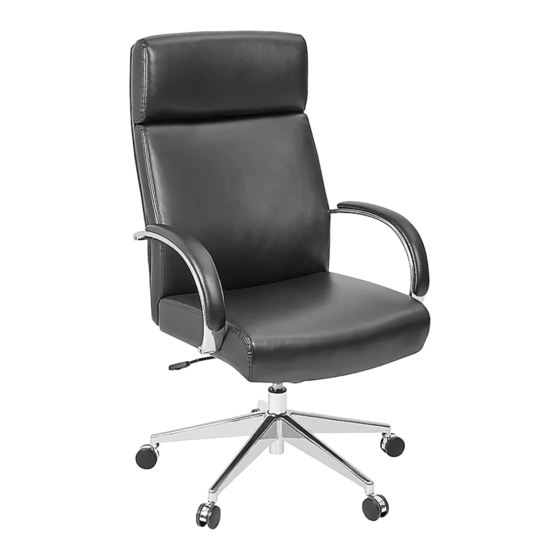
EXECUTIVE
CONFERENCE CHAIR
TOOL INCLUDED
Allen Wrench
Seat Cushion x 1
Back Support x 1
Figure 1
PAGE 1 OF 9
1-800-295-5510
uline.com
5-Star Base x 1
Gas Lift x 1
Mechanism x 1
ASSEMBLY INSTRUCTIONS
Gas Lift
Caster
PARTS
Caster x 5
Armrest x 2
1. Turn base upside down. Insert casters into legs of
five-star base. Turn base right side up. Insert gas lift
into center of base. (See Figure 1)
Para Español, vea páginas 4-6.
Pour le français, consulter les pages 7-9.
Hardware Kit
8
9
Screw x 4
Screw x 4
5/16 x 1/"
1/4 x 7/8"
10
11
Screw x 4
Lock Washer x 4
5/16 x 2"
12
Plastic Cap x 4
0521 IH-8278
Advertisement

Related Manuals for U-Line H-8278


Summary of Contents for U-Line H-8278
- Page 1 Para Español, vea páginas 4-6. Pour le français, consulter les pages 7-9. H-8278 1-800-295-5510 uline.com EXECUTIVE CONFERENCE CHAIR TOOL INCLUDED Allen Wrench PARTS Hardware Kit Screw x 4 Screw x 4 Seat Cushion x 1 5-Star Base x 1 Caster x 5 5/16 x 1/"...
- Page 2 ASSEMBLY INSTRUCTIONS CONTINUED 2. Align mechanism with holes on bottom of seat Figure 2 cushion with tension knob facing the front of seat. Use four 1/4 x 7/8" screws (8) to secure. (See Figure 2) NOTE: Use Allen wrench to tightly secure all screws.
-
Page 3: Chair Adjustments
ASSEMBLY INSTRUCTIONS CONTINUED 6. Once all screws are installed, fully tighten. Insert Figure 6 plastic caps (12) in holes to cover screws. (See Figure 6) CHAIR ADJUSTMENTS 1. Seat Height Adjustment – To raise seat height, lift lever up with little to no weight on the seat. To lower seat height, lift lever up while sitting. -
Page 4: Instrucciones De Ensamble
H-8278 800-295-5510 uline.mx SILLA PARA SALA DE CONFERENCIAS HERRAMIENTA INCLUIDA Llave Allen PARTES Kit de Tornillería 4 Tornillos 4 Tornillos 1 Asiento Acojinado 1 Base Estrella 5 Ruedas 5/16 x 1/" 1/4 x 7/8" 4 Rondanas de 4 Tornillos 1 Soporte 5/16 x 2"... - Page 5 CONTINUACIÓN DE INSTRUCCIONES DE ENSAMBLE 2. Alinee el mecanismo con los orificios en la parte Diagrama 2 inferior del asiento acojinado con la perilla de tensión volteando hacia la parte frontal del asiento. Use cuatro tornillos de 1/4" x 7/4" (8) para asegurarlo. (Vea Diagrama 2) NOTA: Utilice la llave Allen para apretar todos los tornillos.
- Page 6 CONTINUACIÓN DE INSTRUCCIONES DE ENSAMBLE 6. Una vez que todos los tornillos estén instalados, Diagrama 6 apriételos por completo. Inserte las tapas de plástico (12) en los orificios para cubrir los tornillos. (Vea Diagrama 6) AJUSTES DE LA SILLA 1. Ajuste de la Altura del Asiento – Para aumentar la altura del asiento, levante la palanca sin o con poco peso en el asiento.
-
Page 7: Instructions De Montage
H-8278 1-800-295-5510 uline.ca CHAISE DE CONFÉRENCE POUR CADRE SUPÉRIEUR OUTIL INCLUS Clé Allen PIÈCES Matériel d'installation Vis x 4 Vis x 4 Siège x 1 Base à 5 branches x 1 Roulette x 5 1/4 x 7/8 po 5/16 x 1 / po... - Page 8 INSTRUCTIONS DE MONTAGE SUITE 2. Alignez le mécanisme sur les trous situés au bas Figure 2 du siège, la molette de réglage de tension étant orienté vers l'avant du siège. Fixez à l’aide de quatre vis de 1/4 x 7/8 po (8). (Voir Figure 2) REMARQUE : Utilisez la clé...
- Page 9 INSTRUCTIONS DE MONTAGE SUITE 6. Une fois que toutes les vis sont insérées, serrez Figure 6 fermement. Insérez les capuchons en plastique (12) dans les trous pour couvrir les vis. (Voir Figure 6) RÉGLAGES DE LA CHAISE 1. Réglage de la hauteur du siège – Pour élever la hauteur du siège, soulevez le levier avec peu ou sans poids sur le siège.
Need help?
Do you have a question about the H-8278 and is the answer not in the manual?
Questions and answers