
Subscribe to Our Youtube Channel
Related Manuals for LG LSW901


Summary of Contents for LG LSW901
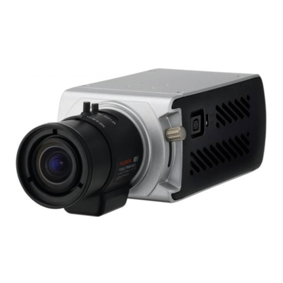
- Page 1 OWNER'S MANUAL Color Video Network Camera Please read this manual carefully before operating your set and retain it for future reference. MODEL LSW900 LSW901 P/NO : MFL62591970 1011 (V2.0)
- Page 2 FCC WARNING: This equipment may generate or use radio CAUTION frequency energy. Changes or modifications to this equip- ment may cause harmful interference unless the modifica- tions are expressly approved in the instruction manual. The RISK OF ELECTRIC SHOCK user could lose the authority to operate this equipment if DO NOT OPEN an unauthorized change or modification is made.
- Page 3 Caution: This installation should be made by a qualified • Caution: Danger of explosion if battery is incorrectly replaced. Replaced only with the same or equivalent service person and should conform to all local codes. type recommended by the manufacturer. Dispose Caution: To avoid electrical shock, do not open the cabi- of used batteries according to the manufacturer’s net.
- Page 4 LG Electronics hereby declares that this/ Disposal of your old appliance these product(s) is/are in compliance with the essential requirements and other relevant When this crossed-out wheeled bin provisions of Directive 2004/108/EC, symbol is attached to a product it means 2006/95/EC, and 2009/125/EC.
- Page 5 Important Safety Instructions Read these instructions. and the point where they exit from the apparatus. Keep these instructions. 11. Only use attachments/accessories specified by the manufacturer. Heed all warnings. 12. Use only with the cart, stand, tripod, bracket, or table Follow all instructions.
- Page 6 Cautions for Safe Operation Handling of the unit Operating and storage location Be careful not to spill water or other liquids on the unit. Be Avoid viewing a very bright object (such as light fittings) cautious not to get combustible or metallic material inside during an extended period.
-
Page 7: Table Of Contents
Contents Features ..............8 Accessing the LG IP device ........19 LG Smart Web Viewer Overview ......20 Part Names and Functions ........9 Configuring the LG IP camera ........24 OSD Menu Setup............51 Connections ............12 Troubleshooting ..........63 Precautions ..............12 Connection Overview ..........12 Open source software notice ...... -
Page 8: Features
Features The LG Color Video IP Camera is designed to use on an • High resolution and high sensitivity with a 6 mm Ethernet network and must be assigned an IP address to Vertical Double Interline CCD. make it accessible. -
Page 9: Part Names And Functions
Part Names and Functions a Lens mount cap c d The lens mount of the camera is covered using a cap to protect it. Remove the lens cap covering the lens. b Flange-back adjustment lever c Lens iris output connector (LENS) This 4- pin connector is used to send the Iris control signal and power supply to an auto-iris type lens. - Page 10 Part Names and Functions f External device connectors g h • TRX +/TRX - Terminals: Connect to an external controller of RS-485 format. • A IN(R)/A IN (Sensor input) Terminals: Provides physical interface for sensor. • A OUT(R)/A OUT (Relay output) Terminals: Provides physical interface for Alarm/Relay.
- Page 11 Part Names and Functions k VIDEO OUT Supplies analog video signal (composite) to the con- nected device. l AUDIO IN (Line Level Input) Input for a mono microphone, or a line-in mono signal. m ETHERNET/POE Port Connects to a PC or a network via a hub with a 10 BASE-T/100 BASE-TX cable attached RJ-45 connec- tor.
-
Page 12: Connections
Connections Precautions • Be sure to switch off the unit before installation and connection. • The installation should be made by qualified service personnel or system installers. • Do not expose the power and connection cables to moisture, which may cause damage to the unit. Connection Overview RS-485 RS-485... -
Page 13: Connecting Display Device
Connections Connecting Display Device Connect the IP camera to your network using a standard RJ-45 network cable as shown below. Connect the video signal between the IP camera and the monitor. Broadband Broadband Router Router Service Service PoE Device PoE Device (IEEE802.3af ) (IEEE802.3af ) Connecting Network... -
Page 14: Connecting Power Source
Connections Connecting Power Source To use the PoE (Power over Ethernet) device Connect the PoE cable to the LAN port on the unit. Connect power, using one of the methods listed below: You must use the “IEEE802.3af” standard PoE device. To use the power adapter Connect a DC 12 V / AC 24 V power source to the power input terminal as shown below. -
Page 15: Connecting Rs-485 Device
Connections RS-485 TRX + Unit TRX - Connecting RS-485 Device Connecting Alarm Device Use these ports to connect an external device of RS-485 Alarm terminals are used to connect the alarm (relay) format. devices such as sensors, door switches, etc. A IN(R)/A IN (Sensor Input ) RS-485 TRX +... -
Page 16: Connecting Microphone And Speaker Device
Connections Connecting Microphone and A OUT(R) / A OUT (Relay Output) Connect the alarm (relay) device to the relay output Speaker Device terminal. Alarm signal is outputted at an event occurrence. Optionally connect an active speaker and/or external microphone with a built-in amplifier. Alarm (Relay) Device Note:... -
Page 17: Mounting The Camera
Connections Mounting the camera The mounting bracket can be secured on either the top or bottom of the camera. Use the same set of screws to attach the mounting bracket on the camera. Note: If using a camera mounting bracket, select a location that is strong enough to bear the full weight of the camera and the mounting bracket for long periods, and install the cam- era and mounting bracket securely. -
Page 18: Operation And Settings
Recommended PC Requirements supply is used. • Check the connections of the LG IP device for the cor- The LG IP device can be used with most standard operating rect conditions. systems and browsers. -
Page 19: Accessing The Lg Ip Device
Accessing the LG IP device Logging in to the LG Smart Web Viewer The LG Smart Web Viewer can be used with most You can access the LG IP device by following the below web browsers. The recommended browser is Internet steps. -
Page 20: Lg Smart Web Viewer Overview
Operation and settings LG Smart Web Viewer Overview 3.2 Enter the IP address of the LG IP device in the address bar of the browse. 3.3 Enter the user name and password set by the administrator. 3.4 Click the [OK] button and then the LG Smart Web Viewer is displayed in your browser. - Page 21 Operation and settings Item Description Select the video image size from the drop-down list. (AUTO, D1 or CIF) The initial view size is set to AUTO. The AUTO option sets the view size according to the Server’s resolution. Displays the current video codec of the selected video stream (Master or Slave). Check this option as the network connection type (TCP or UDP).
- Page 22 If you want to exit the Configuration menu, select one of the video stream in the Live view drop-down list. Displays the current surveillance live screen. You can monitor the camera image on the live view window of the LG Smart Web Viewer.
- Page 23 Operation and settings Click this button to connect or disconnect the audio communication between the LG IP device and the connected PC. (Color icon: On, Gray scale icon: Off.) Click this button to switch the microphone off and on for the computer.
-
Page 24: Configuring The Lg Ip Camera
Operation and settings Configuring the LG IP camera Configuration menu overview The following table shows the list of menu items. The features and options of the LG IP camera are config- Main Menu Sub Menu ured through the Configuration menu. - Page 25 Operation and settings System settings Main Menu Sub Menu User Basic Version Event schedule Displays the current version of Firmware, Hardware, Event server Software and Web Client. Event Sensor & Relay...
- Page 26 Operation and settings Date & Time Time mode > Synchronize with NTP Server: Select if you want to synchronize the IP device’s date and time with those of the time server called NTP (Network Time Protocol). Specify the NTP server’s name. Click the [Test] button for con- nection test to the server.
- Page 27 Operation and settings Maintenance to specify the folder and save the setting data of the IP device. This configuration backup can be restored whenever needed. > Restore: Click the [Browse] button and select the file in which the configuration setting data is stored and click the [Upload] button.
- Page 28 Language values. (Except for Network settings, PTZ Protocol and Preset settings.) Log & Report Language list Select a language for the LG Smart Web Viewer con- figuration menu and information display. • Save: Click this button to confirm the settings.
- Page 29 Operation and settings Audio & Video settings General > Contrast: Edit the contrast value from 0 to Camera 100. Selecting 100 provides the image with the highest contrast. > Brightness: Edit the brightness of the camera. It is brighter when a large value is selected and it is darker when a small value is selected.
- Page 30 Operation and settings Stream NTSC: D1 (704 x 480), HALF D1 (704 x 240), CIF (352 x 240) and QCIF (176 x 112) PAL: D1 (704 x 576), HALF D1 (704 x 288), CIF (352 x 288) and QCIF (176 x 144) >...
- Page 31 Operation and settings CBR: The video quality may vary in order Audio In to preserve a constant bit rate. > Enable: Click the check box if you want to > Stream quality: If the [Quality] option set send the audio from the microphone input to VBR, this option is displayed.
- Page 32 Camera ID: Enter the PTZ device ID. Make the same ID as the PTZ device. > Pan speed: Enter the panning speed of the PTZ device in the edit box. Default value for the LG Multix Protocol is 60 and ranges from 0 to 127.
- Page 33 > Parity: Select the desired parameter. The par- device in the edit box. Default value for the ity bit, added to the data, to perform parity LG Multix protocol is 60 and ranges from 0 check. to 127. > Stop bit: Enter the desired parameter. The >...
- Page 34 Operation and settings Preset Set the Pan, Tilt, Zoom or Focus speed options. Preview Click the [Save] button to confirm the settings. You can see the settings screen from the preview Pattern window. You can activate the camera in a repeating pattern. The pattern is programmed by recording your manual pan, tilt, and zoom operations.
- Page 35 Operation and settings > To play the pattern Note: Click the [Play] button to play the pro- If you set the HOME position, check the [Set grammed pattern. home position] option. Click the [Stop] button to stop playing. • Remove: Click to delete the preset position. Preset Select the preset from the list.
- Page 36 Operation and settings > To tour the preset positions Motion detect Choose the preset in the [Preset]. Click the [Add] button in the [Preset tour]. Repeat the steps 1 to 2 to add another preset. Click the [Save] button to confirm the preset tour list.
- Page 37 Operation and settings Network settings General > Sensitivity: Enter the sensitivity to detect an Basic object in motion. > Save: Click this button to confirm the set- tings. How to set the motion detection window Click the [Add] button. The motion detection win- dow is displayed.
- Page 38 Operation and settings > RTSP port: Check RTSP port. The default port RTP stream is 554. Other ports can be selected within RTP (Real-time Transport Protocol) is an internet protocol the range 1 025 to 65 535. that allows programs to manage the real-time transmission >...
- Page 39 Operation and settings Master / Slave Data RTP port: Specify the VA data port number used for the multicast stream- > RTP unicast: When enabled the transmis- ing. It is initially set to 6 666 and you sion of the data to the specified equipment can edit this between 1 025 and 65 534.
- Page 40 Operation and settings TCP/IP Note: You should register the SMTP server on the Event server setting to set this function. > Statically set: Select this option when you set a fixed IP address, with this setting, specify the IP address, Subnet mask and default gateway manually.
- Page 41 Operation and settings DDNS IP filtering This free service is very useful when combined with the LG The access of the IP addresses in the list are allowed or DDNS Server. It allows the user to connect the IP device denied according to the choice made in the drop-down list using the URL, rather than an IP Address.
- Page 42 Operation and settings IP list "From" and the end IP address to "To". You can also add an IP address by entering the > Basic policy: Select the basic policy type. same IP address to "From" and "To". Allow all: Allow all the IP address basi- cally, but the IP addresses in the list are Click the [Save] button.
- Page 43 Operation and settings User settings User list > Add the User Basic You can register a new user with various The IP device is shipped with the login rights of administra- access rights. tor only. If others need to access the IP device excluding Click the [Add] button.
- Page 44 Operation and settings Power user: Use of the lim- Change the Password or Authority, then ited functions of the system (The click the [Save] button to confirm your Configuration menu is not allowed. selection. A power user can use the Live >...
- Page 45 Operation and settings Note: Preview window of the IP device setting and preset setting are affected by this setting. • Save: Click this button to confirm the settings. Event settings Event schedule When an event (VA/Sensor Event) occurs, this unit records the live images and routes as configured.
- Page 46 Operation and settings FTP server/SMTP server: Uploading of images to an FTP server, or e-mail notifica- tion. Move camera to: Moves the camera to preset position. Control relay: The relay is acti- vated or deactivated. • Stream: Selects the stream of the Event schedule list connected camera.
- Page 47 Operation and settings Event Server > To add the FTP server Click the [Add] button. FTP server set- Event Servers are used to receive the recorded video clip ting window is displayed. and/or notification messages. Set the FTP server options. Alias: Type the FTP Server name to upload the image files.
- Page 48 Operation and settings > To edit the FTP server Alias: Enter the SMTP server name. Choose the FTP server in the FTP server User ID: Enter the user ID of the list. SMTP server. This would be the one who owns the mail account. Click the [Edit] button.
- Page 49 Operation and settings Subject: Enter the subject/title of Sensor & Relay the e-mail. Message: This message can describe the information of the acquired IP address, etc. Click the [Save] button to confirm the settings. > To edit the SMTP server Choose the SMTP server in the SMTP server list.
- Page 50 Operation and settings Stop: Click to stop the relay. • Save: Click this button to confirm the settings. Fan fail notification > Control relay: Marks up when you want to activate the selected relay. > SMTP server: Selects the SMTP server. By selecting this option an e-mail notification is sent to the user indicating a failure in the fan operation.
-
Page 51: Osd Menu Setup
Operation and settings OSD Menu Setup Main Menu Sub Menu Contents The following table shows the list of menu items and op- PUSH tions. You can adapt the camera to your requirements by INDOOR, setting up the respective items in these menus. COLOR TEMP OUTDOOR WHITE BAL... - Page 52 Operation and settings Main Menu Sub Menu Contents Main Menu Sub Menu Contents ZOOM MASK NUMBER AREA1 to AREA8 D-ZOOM DISPLAY ON/OFF TILT EXIT GRAY, WHITE, COLOR BLACK, D-EFFECT OFF/ V-FLIP/ MIRROR/ ROTATE PRIVACY SHARPNESS 0 to 68 HEIGHT 4 to 100 SPECIAL STABILIZER OFF/ ON...
- Page 53 Select [EXIT] option then click button to exit the setup menu. In the submenu, use button to Click the [OSD control] button on the LG Smart Web select the [EXIT] then use button to select a Viewer. mode and click button to exit the setup menu.
- Page 54 Operation and settings Exposure settings button to select a mode then click button. • WDR: WDR (Wide dynamic range) feature can be very helpful to cope with very challenging light- ing conditions. It is capable of capturing both of the dark part and bright part and combining the differences into a scene to generate a highly real- istic image as original scene.
- Page 55 Operation and settings AGC (Automatic Gain Control) > GRAY SCALE: Use button to select If the images are too dark, change the maximum [AGC] a gray scale. value to make the images brighter. (GRAYyD.GRAYyBLACK). > USER SCALE: Use button to select a Select the [AGC] option on the [EXPOSURE] menu.
- Page 56 Operation and settings White Balance settings button to select a mode. Select the method by which the camera shifts its output • AUTO: Adjust the sensitivity of the picture auto- colors to compensate for the color of a light source. matically.
- Page 57 Operation and settings Day/Night settings > When the scene contains mostly high color temperature objects, such as a blue sky or sunset. > When the scene is dim. • AWC b PUSH: If you select the AWC b PUSH mode, you will be able to set up the White Balance automatically using button.
- Page 58 Operation and settings 3D-DNR setting > LEVEL: Use button to select a level. (LOWyMIDDLEyHIGH) > DWELL TIME: Use button to select a dwell time. (5, 10, 15, 30 or 60 SEC) • DAY: Color mode enabled. • NIGHT: Black-and-white mode enabled. Select [3D-DNR] option.
- Page 59 Operation and settings Privacy Mask setting button to select the color of the mask zone box on the [COLOR] option. This function is aiming at the protection of personal pri- vacy. The selected part is not displayed on the screen. Up button to select an option then use to 8 zones can be registered.
- Page 60 Operation and settings Special menu settings • PAN: Use button to move the screen. (left or right) • TILT: Use button to move the screen. (up or down) D-EFFECT (Digital effect) You can select the digital effect. Select the [D-EFFECT] option on the [SPECIAL] menu. D-ZOOM button to select a digital effect.
- Page 61 Operation and settings • OFF: To display the picture with grayscale. button to adjust the option. If you set the sharpness value to higher, the image outline USER TITLE becomes sharp. If you set to lower value, the image You can use the camera identification to assign a number outline becomes dim.
- Page 62 Operation and settings Reset setting • CLR: Clear all entered characters and numbers. • POS: Move the USER TITLE position on the screen using the arrow buttons. • END: Confirm your selection or exit the setting. • A(Blank): Insert a space at the cursor position. •...
-
Page 63: Troubleshooting
Fault symptoms, possible causes and remedial actions are • IP Conflicts: If the LG network device is set with a static provided here. IP address and if the DHCP option is set then there may be IP’s same as the network device and other net- IP Setting problems work partner. - Page 64 If the video streaming does not start on the Web • Firewall Protection: Check for the internet firewall with browser, install the LG Web Client ActiveX program on the system administrator, either he has to do port for- your computer following the instructions on the Web warding or modify the DMZ function on the router.
- Page 65 Troubleshooting • Select the Night mode if the network camera is con- Audio condition nected at a place where surrounding light is less or • The client computer that is interacting with the cam- dark. era needs to have a sound card that is functional to support speaker and microphone.
-
Page 66: Open Source Software Notice
. LGPL LIBRARIES: Glibc, libelf, libesmtp, live.media LG Electronics offers to provide source code to you on CD-ROM for a charge covering the cost of performing such distribution, such as the cost of media, shipping and han- dling upon e-mail request to LG Electronics at: opensource@lge.com... - Page 67 Open source software notice This product includes • lighttpd : Copyright © 2004, Jan Kneschke, incre- mental • dhcp client : • ntpdate : Copyright © David L. Mills 1992-2006 Copyright © 2004-2008 by Internet Systems Consortium, Inc. (“ISC”) • OpenSSL : Copyright ©...
- Page 68 Open source software notice > Copyright 1993, 2002, 2006 David Rowe NONINFRINGEMENT. IN NO EVENT SHALL THE AUTHORS OR COPYRIGHT HOLDERS BE LIABLE FOR ANY CLAIM, > Copyright 2003 EpicGames DAMAGES OR OTHER LIABILITY, WHETHER IN AN ACTION > Copyright 1992-1994 Jutta Degener, Carsten OF CONTRACT, TORT OR OTHERWISE, ARISING FROM, OUT Bormann OF OR IN CONNECTION WITH THE SOFTWARE OR THE USE...
-
Page 69: Specification
Specification Item LSW900 LSW901 Image Device 6 mm Vertical Double Interline CCD Lens Type C/CS Mount Video Out 1.0 Vp-p Composite Signal (75 Ω) Auto Gain Control OFF/ LOW/ MIDDLE/ HIGH Exposure ALC/ELC Electric Shutter 1/50 to 1/90 000 (PAL), 1/60 to 1/90 000 (NTSC) - Page 70 Specification Item LSW900 LSW901 DIS(Stabilizer) ON/OFF Digital Effect OFF/ V-Flip / Mirror / Rotate Resolution (Max) 704 x 480 (NTSC), 704 x 576 (PAL) Output RJ-45 (Network), CVBS (Monitor) Frame Rate (Max) 30 fps/25 fps(NTSC/PAL) Compression H.264 (Basic Profile)/MJPEG Dual Stream...
- Page 71 Specification Item LSW900 LSW901 Event Detection Sensor In, Motion Detect Sensor In, Motion Detect, VCA Event Notification Relay, SMTP, FTP ID/Password Multi level user ID/password (Admin, Power, Normal, Customer) Encryption HTTPS (SSL,TLS) Physical Layer 10/100 base TX Ethernet TCP/IP(IPv4), HTTP, HTTPS, RTP, RTSP, UDP, DHCP, FTP, SMTP, NTP, ARP, ICMP,...
- Page 72 BZ03...
Need help?
Do you have a question about the LSW901 and is the answer not in the manual?
Questions and answers