
Subscribe to Our Youtube Channel
Related Manuals for Clarke 195TEC


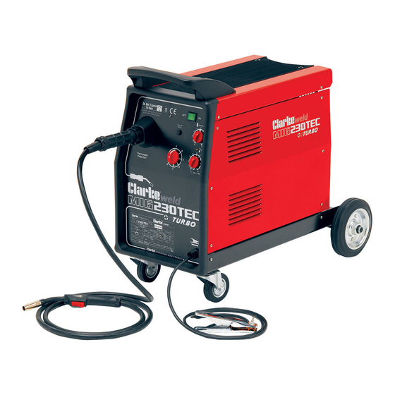
Summary of Contents for Clarke 195TEC
- Page 1 MIG WELDER Model Nos. 195TEC • 205TE • 230TEC OPERATING & MAINTENANCE INSTRUCTIONS 0820 - ISS6...
-
Page 2: Welder Specifications
100% CO - Mild Steel The details and specifications contained herein, are correct at the time of going to print. However, CLARKE International reserve the right to change specifications at any time without prior notice. Consult ma- chines data plate. -
Page 3: Environmental Recycling Policy
Thank you for purchasing this CLARKE MIG Welder, designed to operate using a gas cylinder with plain metal welding wire ONLY. This is explained in greater detail within the manual. Before attempting to operate the machine, it is essential that you read this manual thoroughly and carefully follow all instructions given. -
Page 4: Electromagnetic Interference (Emc)
ELECTROMAGNETIC INTERFERENCE (EMC) Whilst this unit complies with EMC regulations, the user is responsible for installing and using the welding equipment according to the manufacturers instructions. If electromagnetic disturbances are detected then it shall be the responsibility of the user of the welding equipment to resolve the situation. In some cases this remedial action may be as simple as earthing the welding circuit, see ‘Note’. - Page 5 take additional precautions such as filtering of the mains supply. Consideration should be given to shielding the supply cable of permanently installed welding equipment, in metallic conduit or equivalent. Shielding should be electrically continuous throughout its length. The shielding should be connected to the welding power source so that good electrical contact is maintained between the conduit and the welding power source enclosure.
- Page 6 SAFETY PRECAUTIONS FOR ALL TYPES OF WELDING 1. WARNING: As with all machinery, there are certain hazards involved with their operation and use. Exercising respect and caution will considerably lessen the risk of personal injury. However, if normal safety precautions are overlooked, or ignored, personal injury to the operator may result.
- Page 7 C) Fire and explosion prevention Causes of fire and explosion are: 1) combustibles reached by the arc, flame, flying sparks, hot slag or heated material; 2) misuse of compressed gases and cylinders; 3) short circuits. BE AWARE THAT flying sparks or falling slag can pass through cracks, along pipes, through windows or doors, and through wall or floor openings, out of sight of the goggled operator.
- Page 8 3. ELECTRIC ARC (MIG, TIG) WELDING Comply with precautions in 1 above, and this section. Arc welding, properly done, is a safe process, but a careless operator invites trouble. The equipment carries high currents at significant voltages. The arc is very bright and hot. Sparks fly, fumes rise, ultraviolet and infrared energy radiates, weldments are hot.
- Page 9 3B) TOXIC FUME PREVENTION Comply with precautions in 2B. Generator engine exhaust must be vented to the outside air. Carbon monoxide can kill. 3C) FIRE AND EXPLOSION PREVENTION Comply with precautions in 2C. Equipment’s rated capacity. Do not overload arc welding equipment.
- Page 10 2) Electrode holders Fully insulated electrode holders should be used. Do NOT use holders with protruding screws or with any form of damage. 3) Connectors Fully insulated lock-type connectors should be used to join welding cable. 4) Cables Frequently inspect cables for wear, cracks and damage. IMMEDIATELY REPLACE those with excessively worn or damaged insulation to avoid possibly lethal shock from bared cable.
-
Page 11: Preparation Of The Working Area
AND never use the machine with any of the panels removed. • NEVER attempt any electrical or mechanical repair unless your are a qualified technician. If you have a problem with the machine contact your local CLARKE dealer. - Page 12 • NEVER use or store in a wet/damp environment. DO NOT EXPOSE TO RAIN. • The MIG welding process uses an INERT gas to protect the weld pool. It is important to ensure the appropriate gas is being used. NEVER use gas from a cylinder, the content of which is unknown.
-
Page 13: Safety Equipment
SAFETY EQUIPMENT A comprehensive range of CLARKE safety equipment for use when welding is available from your local dealer. MIG WELDING - PRINCIPLES OF OPERATION MIG (Metal Inert Gas) welding is a process in which a power wire electrode is fed continuously into the weld pool at a controlled, constant rate. -
Page 14: Electrical Connections
ELECTRICAL CONNECTIONS WARNING: THIS MACHINE MUST BE EARTHED. This welder must be connected to a 230 volt (50Hz) supply, having a rated capac- ity of greater than 13 amps. A 13 Amp (BS1363) plug is not suitable for this device. Connect the three core mains lead to a suitably fused supply through an isolator or heavy duty plug. -
Page 15: Unpacking And Parts Identification
UNPACKING & PARTS IDENTIFICATION The side panel is hinged at its rear edge: Open by pulling sideways at the front edge, lay out all components contained within, and check to ensure that they are all correct according to the list below. Fig.1 2 Wheels 1 Axle... - Page 16 ASSEMBLY A. Attaching the Torch Fig.2 Mig 195TEC - Mig 205TE A. It is necessary to fit the torch hose assembly (7) to the machine, but before doing so you must first measure the length of protrusion of the liner (9) from the brass nut (10).
- Page 17 B. Loading the Wire NOTE: These machines are designed to accept either the Clarke 5kg or 15kg wire spools of mild steel, stainless steel or aluminium according to the type of metal you wish to weld.Wire spools must be purchased separately. See your Clarke dealer for full details.
- Page 18 Fig.6 NOTE: The Plastic knob, item 7 is also used to apply slight tension to the wire spool. This prevents the spool from running freely, which could cause the wire to unspool, creating a ‘birds nest’ tangle within the side compartment.
- Page 19 A regulator is provided, complete with outlet pressure gauge for use with argon or argon mix gas bottles. Should you require to use Carbon Dioxide, it will be necessary for you to purchase an appropriate regulator with a female connector. Your Clarke dealer will be happy to advise in this regard.
-
Page 20: Preparation For Welding
PREPARATION FOR WELDING Attach the earth clamp to the bare metal to be welded. Ensure contact is good . Make sure that the wire-roller groove in the roller corresponds to the diameter of the welding wire being used. Refer to “Loading wire” above. Plug the machine into a 230V AC 50Hz outlet. -
Page 21: Wire Size Specification Chart
WARNING Make sure all flammable materials are removed from the work area. (ii) Never look directly at the welding arc, it can seriously damage your eyes. Always use an approved welding mask or helmet. (iii) Wear protective clothing so that all skin areas are covered. (iv) Keep a fire extinguisher handy. -
Page 22: Troubleshooting
TROUBLE SHOOTING PROBLEM PROBABLE CAUSE REMEDY 1. No life from Check fuses and mains lead a) Replace fuses as necessary. welder If problem persists. return welder to your local dealer. b) Check fuse size. Return welder to your local dealer. 2. - Page 23 PARTS DRAWING - MIG 195TEC...
- Page 24 PARTS LIST - MIG 195TEC Description Part No: Motor Contr. PCB EM22710048 Motor EM04600156 Motor Brush For Motor D.48 EM22810064 Gas Solenoid Valve 4W 220V 50Hz EM22900001 Complete Thermostat + Support EM04600113 Resistance 3 Ohm D.16 EM22305004 Rectifer Pins 16/4/2 F...
- Page 25 PARTS DRAWING - MIG 205TE...
- Page 26 PARTS LIST - MIG 205TE Item Description Part No: PC Board HE11 220V EM22710048 Wire Feeding Meter 24V EM04600156 Gas Solenoid Valve 4W 220V 50Hz EM22900001 Complete Thermostat 6A EM04600113 Rectifier PMS 16/4/2 F EM22400009 Fan 230V EM22800002 Chain EM04600205 Tarch Grommet EM21690268 Handle...
- Page 27 PARTS DRAWING - MIG 230TEC...
- Page 28 PARTS LIST - MIG 230TEC Part No: Description Motor Contr. Rob. Hell .01 220V 100x120 EM22710048 Motor MP48 24V EM04600156 Motor Brush For Motor D.48 EM22810064 Gas Solenoid Valve 4W 220V 50Hz EM22900001 Complete Thermosta + Support EM04600113 Rectier Pins 16/4/2 F EM22400009 Resistance 3 Ohm D.16 L=90 EM22305004...
- Page 29 WIRING DIAGRAM - MIG 195TEC & MIG 230TEC...
- Page 30 WIRING DIAGRAM - MIG 205TE...
-
Page 31: Declaration Of Conformity
DECLARATION OF CONFORMITY...
Need help?
Do you have a question about the 195TEC and is the answer not in the manual?
Questions and answers