Table of Contents
Advertisement
Quick Links
Advertisement
Table of Contents

Subscribe to Our Youtube Channel
Related Manuals for Clarke MIG165TEM


Summary of Contents for Clarke MIG165TEM
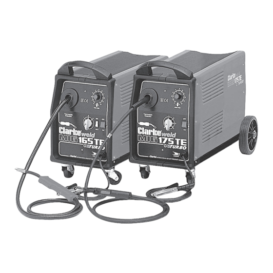
- Page 1 MIG165TEM • MIG175TECM OPERATING & MAINTENANCE INSTRUCTIONS 0218...
-
Page 2: Welder Specifications
Interpolate for other welding currents Please note that the details and specifications contained herein, are correct at the time of going to print. However, CLARKE International reserve the right to change specifications at any time without prior notice. ALWAYS CONSULT THE MACHINE’S DATA PLATE... -
Page 3: Table Of Contents
Wiring Diagrams ................28 - 30 PARTS AND SERVICE CONTACTS For Spare Parts and Service, please contact your nearest dealer, or CLARKE International, on one of the following numbers. PARTS & SERVICE TEL: 020 8988 7400 PARTS & SERVICE FAX: 020 8558 3622 e-mail as follows: PARTS: Parts@clarkeinternational.com... -
Page 4: Guarantee
Thank you for purchasing this CLARKE MIG Welder, designed to operate using a gas cylinder with plain metal welding wire ONLY. This is explained in greater detail within the manual. Before attempting to operate the machine, it is essential that you read this manual thoroughly and carefully follow all instructions given. -
Page 5: Electromagnetic Interference (Emc)
ELECTROMAGNETIC INTERFERENCE (EMC) Whilst this unit complies with EMC regulations, the user is responsible for installing and using the welding equipment according to the manufacturers instructions. If electromagnetic disturbances are detected then it shall be the responsibility of the user of the welding equipment to resolve the situation. In some cases this remedial action may be as simple as earthing the welding circuit, see ‘Note’. - Page 6 take additional precautions such as filtering of the mains supply. Consideration should be given to shielding the supply cable of permanently installed welding equipment, in metallic conduit or equivalent. Shielding should be electrically continuous throughout its length. The shielding should be connected to the welding power source so that good electrical contact is maintained between the conduit and the welding power source enclosure.
-
Page 7: Safety Precautions
SAFETY PRECAUTIONS FOR ALL TYPES OF WELDING 1. WARNING: As with all machinery, there are certain hazards involved with their operation and use. Exercising respect and caution will considerably lessen the risk of personal injury. However, if normal safety precautions are overlooked, or ignored, personal injury to the operator may result. - Page 8 C) Fire and explosion prevention Causes of fire and explosion are: 1) combustibles reached by the arc, flame, flying sparks, hot slag or heated material; 2) misuse of compressed gases and cylinders; 3) short circuits. BE AWARE THAT flying sparks or falling slag can pass through cracks, along pipes, through windows or doors, and through wall or floor openings, out of sight of the goggled operator.
- Page 9 3. ELECTRIC ARC (MIG, TIG) WELDING Comply with precautions in 1 above, and this section. Arc welding, properly done, is a safe process, but a careless operator invites trouble. The equipment carries high currents at significant voltages. The arc is very bright and hot. Sparks fly, fumes rise, ultraviolet and infrared energy radiates, weldments are hot.
- Page 10 3B) TOXIC FUME PREVENTION Comply with precautions in 2B. Generator engine exhaust must be vented to the outside air. Carbon monoxide can kill. 3C) FIRE AND EXPLOSION PREVENTION Comply with precautions in 2C. Equipment’s rated capacity. Do not overload arc welding equipment.
- Page 11 2) Electrode holders Fully insulated electrode holders should be used. Do NOT use holders with protruding screws or with any form of damage. 3) Connectors Fully insulated lock-type connectors should be used to join welding cable. 4) Cables Frequently inspect cables for wear, cracks and damage. IMMEDIATELY REPLACE those with excessively worn or damaged insulation to avoid possibly lethal shock from bared cable.
-
Page 12: Additional Safety Precautions For Mig Welding
AND never use the machine with any of the panels removed. • NEVER attempt any electrical or mechanical repair unless your are a qualified technician. If you have a problem with the machine contact your local CLARKE dealer. - Page 13 PREPARATION OF THE WORKING AREA • NEVER use or store in a wet/damp environment. DO NOT EXPOSE TO RAIN. • The MIG welding process uses an INERT gas to protect the weld pool. It is important to ensure the appropriate gas is being used. NEVER use gas from a cylinder, the content of which is unknown.
-
Page 14: Principles Of Operation
SAFETY EQUIPMENT A comprehensive range of CLARKE safety equipment for use when welding is available from your local dealer. MIG WELDING - PRINCIPLES OF OPERATION MIG (Metal Inert Gas) welding is a process in which a power wire electrode is fed continuously into the weld pool at a controlled, constant rate. -
Page 15: Electrical Connections
ELECTRICAL CONNECTIONS WARNING: THIS MACHINE MUST BE EARTHED. This welder must be connected to a 230 volt (50Hz) supply, having a rated capacity of greater than 13 amps. A 13 Amp (BS1363) plug is not suitable for this device. Connect the three core mains lead to a suitably fused supply through an isolator or heavy duty plug. -
Page 16: Assembly
ASSEMBLY Remove contents from carton and check all components as follows: The side panel is hinged at its rear edge: Open by pulling the securing catch sideways, lay out all components contained within, and check to ensure that they are all correct according to the list below. Fig.1 2 Wheels 1 Axle... -
Page 17: Welding Shield
A regulator is provided, complete with outlet pressure gauge for use with argon or argon mix gas bottles. Should you require to use Carbon Dioxide, it will be necessary for you to purchase an appropriate regulator with a female connector. Your Clarke dealer will be happy to advise in this regard. -
Page 18: Preparation For Use
PREPARATION FOR USE A. Installing the Welding Wire NOTE: These machines are designed to accept either the Clarke 5kg or 15kg wire spools of mild steel, stainless steel or aluminium according to the type of metal you wish to weld.Wire spools must be purchased separately. See your Clarke dealer for full details. - Page 19 Fig.7 Unscrew the pressure roller bracket securing knob (A, Fig 7), sufficient for it to be pulled out of its holder. This releases the pressure roller bracket (B) which, may then be pulled up to expose the welding wire. IMPORTANT! Before fitting ANY wire, ensure the correct groove on the roller is in place.
-
Page 20: Selecting Correct Drive Roller
Close the side panel of the machine, and switch on at the mains or isolator. 10. Set the Wire Feed rotary switch, on the front panel, to position 6 OR 7, switch on the machine and press the trigger. The wire will feed through the hose and when it appears at the torch end, release the trigger, switch off the machine and disconnect from the mains supply. -
Page 21: Mig Welding Operation
OPERATION These machines have 6 welding Fig.11 positions (see the table which follows) in which to regulate current for various conditions, obtainable through a combination of one 2 - position (Min-Max) switch (A, Fig11) and one-3 position switch (B, Fig11). The selection of a welding position is determined by the thicknessof the metal to be welded. -
Page 22: Wire Specification Chart
These drops are often deposited beside the welding seam. The correct rate of wire feed speed (current) and welding voltage, results in very little spatter and a continuous, intensive hissing can be heard from the arc. WIRE SIZE SPECIFICATION CHART MIG165TEM MIG175TECM Wire Speed Steel wire... -
Page 23: Troubleshooting
TROUBLE SHOOTING PROBLEM PROBABLE CAUSE REMEDY 1. No life from Check fuses and mains lead a) Replace fuses as necessary. welder If problem persists. return welder to your local dealer. b) Check fuse size. Return welder to your local dealer. 2. -
Page 24: Parts Lists And Diagrams
PARTS DIAGRAM... - Page 25 165TEM Description Part No. P.C. BOARD E0795 220/240V + FUSE “CSA” 22710037 MOTOR MBT D.40 PINION 04600155 COMPLETE THERMOSTAT 100ø + SUPPORT 04600113 RECTIFIER PMS 12/4/2 F 22400005 COMPLETE FAN 230V 04600057 DIRECT TORCH CONNECTION COVER 21690268 HANDLE FOR WELDING UNITS 21600042 UPPER FRAME SPACER 21690232...
- Page 26 175TEC Description Part No. P.C. BOARD E0795 220/240V + FUSE “CSA” 22710037 MOTOR MP48 24V 04600156 COMPLETE THERMOSTAT 100ø + SUPPORT 04600113 RECTIFIER PMS 16/4/2 F 22400009 COMPLETE FAN 230V 04600057 DIRECT TORCH CONNECTION COVER 21690268 HANDLE FOR WELDING UNITS 21600042 UPPER FRAME SPACER 21690232...
- Page 27 TORCH ASSEMBLY - 165TE Description Part No. Complete Torch Handle EM21690339 Torch Trigger EM21690340 Torch Gas Valve EM23005009 Torch Neck EM23005077 Thread Guide Wire Liner EM23005091 Torch Neck Insulator EM23005090 Head Insulator Torch EM23005093 Gas Diffuser EM23005096 Retainer Spring EM23005095 0,6mm Contact Tip EM23005018 0,8mm Contact Tip...
-
Page 28: Wiring Diagrams
TORCH ASSEMBLY - 175TEC No. Description Part No. Torch Neckfortorch Plus 14 EM23005094 0,6mm Contact Tip For Torch T 1.4-1.6 EM23005018 0,8mm Contact Tip For Torch T 1.4-1.6 EM23005019 1,0mm Contact Tip For Torch T 1.4-1.6 EM23005020 1,2mm. Contact Tip For Torch T 1.4-1.6 EM23005029 Torch Gas Nozzle D.9,5 For Plus 14 EM23005117... - Page 29 WIRING DIAGRAM - 165TE...
- Page 30 WIRING DIAGRAM - 175TEC...
- Page 31 DECLARATION OF CONFORMITY...
Need help?
Do you have a question about the MIG165TEM and is the answer not in the manual?
Questions and answers