Sign In
Upload
Download
Table of Contents
Contents
Add to my manuals
Delete from my manuals
Share
URL of this page:
HTML Link:
Bookmark this page
Add
Manual will be automatically added to "My Manuals"
Print this page
×
Bookmark added
×
Added to my manuals
Manuals
Brands
Clarke Manuals
Welding System
195TE
Operating & maintenance manual
Clarke 195TE Operating & Maintenance Manual
Mig welder
Hide thumbs
1
2
Table Of Contents
3
4
5
6
7
8
9
10
11
12
13
14
15
16
17
18
19
20
21
22
23
24
25
26
27
28
29
30
31
page
of
31
Go
/
31
Contents
Table of Contents
Troubleshooting
Bookmarks
Table of Contents
Welder Specifications
Table of Contents
Parts & Service Contacts
Guarantee
Electromagnetic Interference (EMC)
Welding Cables
Safety Precautions
Additional Safety Precautions for MIG Welding
Principles of Operation
Electrical Connections
Unpacking and Parts Identification
Assembly
Installing the Welding Wire
Connecting the Gas Supply
Welding Shield
Preparation for Use
MIG Welding Operation
Wire Specification Chart
Welding Tips & Maintenance
Troubleshooting
Parts Lists and Diagrams
Wiring Diagrams
Wiring Diagrams
Advertisement
Quick Links
1
Welder Specifications
2
Principles of Operation
3
Mig Welding Operation
4
Wire Specification Chart
5
Parts Lists and Diagrams
6
Wiring Diagrams
Download this manual
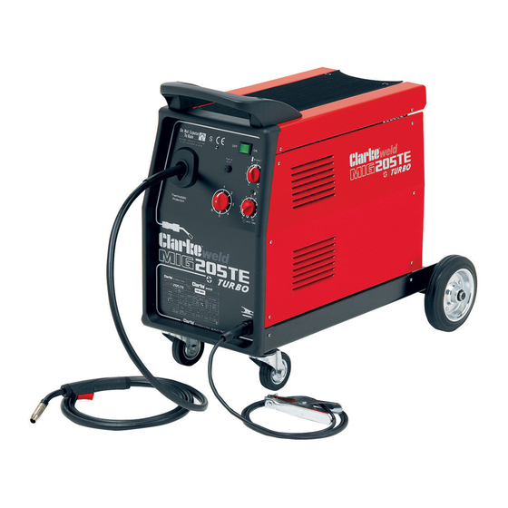
MIG WELDER
Model Nos.
195TE • 205TE • 230TE
OPERATING & MAINTENANCE
INSTRUCTIONS
1104
Table of
Contents
Previous
Page
Next
Page
1
2
3
4
5
Advertisement
Table of Contents
Need help?
Do you have a question about the 195TE and is the answer not in the manual?
Ask a question
Questions and answers
Related Manuals for Clarke 195TE
Welding System Clarke 195TEC Operating & Maintenance Instructions
(33 pages)
Welding System Clarke 100EN Operating & Maintenance Manual
Gas/no-gas mig welder (33 pages)
Welding System Clarke 105EN Operating & Maintenance Manual
Gas/no-gas mig welder (33 pages)
Welding System Clarke 151EN Operating & Maintenance Manual
Gas/no-gas mig welder (33 pages)
Welding System Clarke EASIARC 165 Operation & Maintenance Instructions Manual
160 amp arc welder (17 pages)
Welding System Clarke Fluxcore/MIG 135sg WE6441 Operating Manual
Hot shot spool gun welder (62 pages)
Welding System Clarke EASIARC 110 Operation & Maintenance Instructions Manual
100 amp arc welder (17 pages)
Welding System Clarke Weld MIG 130 TE Operating And Maintenance Instructions Manual
(12 pages)
Welding System Clarke weld MIG107 Operation & Maintenance Instructions Manual
No gas/gas mig welder (33 pages)
Welding System Clarke MIG110E Operating & Maintenance Manual
(43 pages)
Welding System Clarke weld MIG 90EN Operating & Maintenance Instructions
Gas/no-gas (40 pages)
Welding System Clarke 90EN Operating & Maintenance Manual
Gas/no-gas mig welder (33 pages)
Welding System Clarke MIG 152 Operation & Maintenance Instructions Manual
No gas/gas mig welder (28 pages)
Welding System Clarke MMA200 Operation & Maintenance Instructions Manual
200a mma inverter welder (21 pages)
Welding System CLARKE WE6480 MIG 95 Operating & Maintenance Manual
(13 pages)
Welding System Clarke MIG PRO-90 Operating & Maintenance Manual
(35 pages)
This manual is also suitable for:
205te
230te
Table of Contents
Print
Rename the bookmark
Delete bookmark?
Delete from my manuals?
Login
Sign In
OR
Sign in with Facebook
Sign in with Google
Upload manual
Upload from disk
Upload from URL


Need help?
Do you have a question about the 195TE and is the answer not in the manual?
Questions and answers