Table of Contents
Advertisement
Quick Links
Advertisement
Table of Contents

Related Manuals for GHM G 1410


Summary of Contents for GHM G 1410
- Page 1 Operating manual G 1410 Handheld conductivity measuring device...
-
Page 2: Table Of Contents
Qualified personnel.......................... 7 Description ............................ 8 Scope of delivery .......................... 8 Functional description........................... 8 The product at a glance ........................ 9 The G 1410............................ 9 Display elements .......................... 9 Operating elements .......................... 9 Measurement Basics ........................ 11 Conductivity principles ........................ 11 General information about conductivity measuring................ - Page 3 Table of contents Error and system messages...................... 22 Disposal............................. 23 Technical data........................... 24 B-H87.0.01.DB200-2.0 3 / 24...
-
Page 4: About This Documentation
1 | About this documentation G 1410 1 About this documentation 1.1 Foreword Read this document carefully and familiarise yourself with the operation of the product before you use it. Keep this document ready to hand and in the immediate vicinity of the product so that it is available to the personnel/user for reference at all times in case of doubt. -
Page 5: Further Information
G 1410 About this documentation | 1 Instruction Tasks to be carried out by the personnel / user are represented as numbered instruc- tions. Adhere to the sequence of the specified instructions. Representation Shows an illustrative instruction or a configuration of the product. -
Page 6: Safety
2 | Safety G 1410 2 Safety 2.1 Explanation of safety symbols DANGER This symbol warns of imminent danger, which can result in death, severe bodily injury, or severe property damage in case of non-observance. CAUTION This symbol warns of potential dangers or harmful situations, which can cause dam- age to the device or to the environment in case of non-observance. -
Page 7: Intended Use
G 1410 Safety | 2 2.4 Intended use The product is designed for measuring the conductivity in liquids. The measuring cell is connected permanently. 2.5 Qualified personnel For commissioning, operation and maintenance, the relevant personnel must have ad- equate knowledge of the measuring process and the significance of the measure- ments. -
Page 8: Description
3 | Description G 1410 3 Description 3.1 Scope of delivery Please check to ensure the completeness of the product after opening the package. You should find the following components: – Quick reference guide – Handheld measuring device, ready for operation, including batteries –... -
Page 9: The Product At A Glance
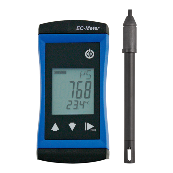
G 1410 The product at a glance | 4 4 The product at a glance 4.1 The G 1410 LCD Display Front view 4.2 Display elements Display Battery indicator Evaluation of the battery status Unit display Display of units or type of mode, min/max/hold... - Page 10 4 | The product at a glance G 1410 Function key Press briefly Freeze measurement (Hold) Return to measurement display Call up next parameter Long press, 2s Open menu, frozen measurement is displayed Close menu, changes are saved 10 / 24...
-
Page 11: Measurement Basics
G 1410 Measurement Basics | 5 5 Measurement Basics 5.1 Conductivity principles Conductivity γ Conductivity describes the capability of a material to conduct electrical current. It is also the inverse of specific resistance. The conductance is the inverse of the meas- ured resistance R. -
Page 12: Total Dissolved Solids / Tds Measurement
5 | Measurement Basics G 1410 5.4 Total dissolved solids / TDS measurement The total dissolved solids measurement - TDS measurement - determines the total dissolved solids, which also called evaporation residue, based on the conductivity and a conversion factor CtdS of the total dissolved solids. Well-suited to conduct simple concentration measurements of salt solutions. -
Page 13: Electrodes / Measuring Cell
G 1410 Measurement Basics | 5 5.6 Electrodes / measuring cell 5.6.1 Design There are basically two different types of measuring cells: 2-pole and 4-pole measur- ing cells. Control and/or evaluation take place in a similar manner; the 4-pole measur- ing cells can compensate well for polarisation effects and contamination to a certain degree with the more elaborate measuring processes. -
Page 14: Operation And Maintenance
6 | Operation and maintenance G 1410 6 Operation and maintenance 6.1 Operating and maintenance notices NOTE The product and conductivity measuring cell must be handled with care and used in accordance with the technical data. Do not throw or strike. - Page 15 G 1410 Operation and maintenance | 6 NOTE Unnecessary screwing places the water-tightness of the product, among other things, at risk and should be avoided. NOTE Read the following handling instructions before replacing batteries and follow them step by step. If disregarded, the product could be damaged or the protection from moisture could be diminished.
-
Page 16: Operation
7 | Operation G 1410 7 Operation 7.1 Commissioning 7.1.1 Explanation Description The product is switched on with the On/Off button. It may be necessary to configure the product after switching on. See Configuration [} p. 16]. Prerequisite – Sufficiently full batteries are inserted in the product. -
Page 17: Configuring Parameters Of The Configuration Menu
G 1410 Operation | 7 4. When you have selected the desired parameter, change the parameter to the de- sired value with the Up button and the Down button. 5. The changes are saved after running through the entire Configuration menu. STOR appears in the display. - Page 18 7 | Operation G 1410 Temperaturkompensation TCOR Do not compensate conductivity measurement Non-linear function for natural water in accordance with EN 27888 (ISO 7888) Ground water, surface water or drinking water Reference temperature for temperature compensation TREF Reference temperature 25 °C or 77 °F 25 °(...
-
Page 19: Adjustment Of The Measuring Input
G 1410 Operation | 7 7.2.4 Adjustment of the measuring input Description The temperature input can be adjusted with the zero point correction and the gradient correction. If an adjustment is made, you change the pre-adjusted factory settings. This is signalled with the T.OF, T.SL or S(L display text when the product is switched on. - Page 20 7 | Operation G 1410 Representation Parameter Values Meaning Zero point correction T.OF 0.00 No zero point correction -5.00 .. 5.00 Zero point correction in °C. and/or at °F -9.00 .. 9.00 Gradient correction of the temperature T.SL 0.00 No gradient correction -5.00 ..
- Page 21 G 1410 Operation | 7 – Display in GKL 100 at 25 °C, setpoint = 1413 µS/cm – Display = 1388 µS/cm – S(L = setpoint / display value – S(L = 1413 µS/cm / 1388 µS/cm = 1.018 NOTE The most precise results can be achieved when the control solution temperature is ad- justed to 25 °C.
- Page 22 8 | Error and system messages G 1410 8 Error and system messages Display Meaning Possible causes Remedy Range switching or Measuring cell de- Wait for the transient effect ---- measured value un- fect of the controller stable Contamination or air...
- Page 23 G 1410 Disposal | 9 9 Disposal Separation by material and recycling of device components and packaging must take place at the time of disposal. The valid regional statutory regulations and directives applicable at the time must be observed. NOTE The device must not be disposed of with household waste.
- Page 24 10 | Technical data G 1410 10 Technical data Measuring range Conductivity 0 .. 2000 S/cm 0.00 .. 20.00 mS/cm 0.0 .. 100.0 mS/cm Specific resistance Salinity 0.0 .. 50.0 g/kg 0 .. 2000 mg/l Temperature -5.0 .. +105.0 °C (23.0 .. +221.0 °F) – the conductivity measur- ing cells can be exposed temporarily to temperatures of up to 100 °C and permanently to temperatures of up to 80 °C.
Need help?
Do you have a question about the G 1410 and is the answer not in the manual?
Questions and answers