Table of Contents
Advertisement
Advertisement
Table of Contents

Related Manuals for Mighty Mule MM136

Summary of Contents for Mighty Mule MM136
- Page 1 MM136 Wireless Gate Entry Intercom Wireless and Wired Installation Instructions...
-
Page 2: Table Of Contents
Learning an MM136 to an MM371, MM372, MM571 or MM572 Automatic Gate Opener . . . . . . . . . . . . . . -
Page 3: Wireless Gate Entry Intercom
Base Unit Crystal clear two-way communication up to 500 feet wireless. Thank you for purchasing the Mighty Mule Wireless Gate Entry Intercom . Please read the directions carefully and completely before installing . SAFETY NOTE: Never install the keypad portion of this unit where a person can reach through the gate to 10’... -
Page 4: Features Of The Intercom/Keypad
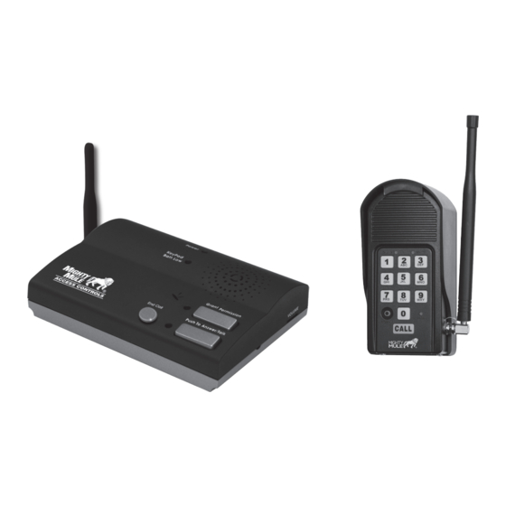
Features of the Intercom/Keypad The INTERCOM has two separate units . The KEYPAD (outside unit) should be mounted outside the gate allowing the driver of the vehicle approaching the property to press the CALL button from their vehicle . The BASE (inside unit), with it’s rechargeable battery, can be plugged into any 110 Volt AC outlet for use while charging . -
Page 5: Keypad Description
7 . Relay output: Used to connect Keypad to gate opener in hard-wired applications . 8 . ID SET button: This button is used only when there is another pair of Mighty Mule wireless . 9 . Reset button: Pressing this button for 2 seconds will reprogram key pad to factory settings . All codes are deleted . Default master code is 1234 . -
Page 6: Wireless Installation Of The Keypad
. To forget the MM136, simply follow steps 1 through 5 above then test the keypad to verify that it no longer activates the Operator . Note for MM271: The gate must be in the closed position with the arm extended to delete a PIN code . The gate can be in any position to add a PIN code . -
Page 7: Wireless Installation Using The Dip Switches
Wireless Installation Using the DIP Switches Step 1: Mount the keypad cover using the screws provided . Set the keypad DIP switches to match your entry transmitter’s DIP switch settings . NOTE: If you have not changed your opener’s transmitter code from the factory setting, see the “Setting Your Personal Transmitter Code”... -
Page 8: Wired Installation Of The Keypad
Wired Installation of the Keypad NOTE: If you also plan to power the keypad with the gate opener’s power source, run two pairs of wires as described below . One pair to hard-wire the keypad and the other pair to connect the keypad to the gate opener’s battery . Step 1: Turn the gate opener’s power switch OFF . - Page 9 Step 5: Attach the wires from the keypad to the opener control board terminal blocks as shown in wiring diagrams below . Step 6: Replace the control board cover and turn the power switch ON . Test the keypad by entering 1 2 3 4 . Step 7: Program your “Personal Master Code”...
-
Page 10: Control Board Connections
CYCLE gate opener control board. the gate opener control board. terminal on the gate opener control board. Mighty Mule 500 & 502 Control Boards MM560, MM562, MM660, PRO3000XLS Series, and PRO4000XLS Series Control Boards RECEIVER CONTROL INPUTS... -
Page 11: Programming The Keypad
Programming the Keypad Program (Add) New Temporary Programming Interface Entry Code • All codes are four (4) digits in length . • Press and release PROGRAM button . • Entry code is a four (4) digit code needed to activate the gate . •... -
Page 12: Delete All Entry Codes
Delete ALL Entry Codes: Normal Keypad operation: • Press and release PROGRAM button . • If the user enters a 4-digit code that is matched to one of the 25 stored codes, the STATUS light should blink twice and the beeper •... -
Page 13: Intercom Base Unit Installation
Intercom Base Unit Installation Connecting the Battery Remove the battery access cover using a small phillips head screwdriver . Plug the rechargeable Ni-MH battery into the receptacle inside the battery compartment . See diagram to the right . When this is done, replace the battery access cover . -
Page 14: Intercom Id Codes
Intercom ID Codes The Base and Keypad that came in this kit are programmed at the factory to communicate with each other, and do not need the ID Codes programmed . This Base is the MASTER or #1 unit . Adding Additional Base Units If you have purchased additional Base units to enhance your ID SET button... -
Page 15: Test The System
Test the System IMPORTANT: The Base unit and the Keypad can not be within 30 feet of each other when operating . If units are closer than 30 feet the signal will be inconsistent as well as emit speaker feed back . Also, multiple Base units must be no closer than 10 feet from each other to prevent interference . -
Page 16: Keypad Specifications
. Please retain those records . Mighty Mule Sales: 800-543-4283 | Mighty Mule Technical Support: 800-543-1236 • Mon-Fri 8am - 7pm EST • Saturday 10am - 6:30pm EST 5919 Sea Otter Place, Carlsbad, CA, 92010 www .mightymule .com...
Need help?
Do you have a question about the MM136 and is the answer not in the manual?
Questions and answers
whats the distance from key pad to control board
The recommended distance between the keypad and the base unit (control board) for the Mighty Mule MM136 is more than 30 feet. If they are closer than 30 feet, the signal may be inconsistent and cause feedback.
This answer is automatically generated