Table of Contents
Advertisement
Quick Links
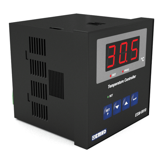
ESM-9910 96 x 96 1/4 DIN
Digital, On/Off Temperature Controller
- 3 D
igits display
- NTC Input or,
PTC Input or,
J type thermocouple or,
K type thermocouple or,
PT-100 2-wire or 3-wire temperature input
( It must be determined in order )
- ON/OFF control form
- Selectable heating and cooling function
- Operating type selection with hysteresis
- Adjustment of temperature offset value
- Minimum pulling time adjustment for control outputs
- Password protection for programming mode
Instruction Manual. ENG ESM-9910 02 V05 07/13
Advertisement
Table of Contents

Related Manuals for EMKO ESM-9910.5.12.0.1/01.00/2.0.0.0


Summary of Contents for EMKO ESM-9910.5.12.0.1/01.00/2.0.0.0
- Page 1 ESM-9910 96 x 96 1/4 DIN Digital, On/Off Temperature Controller - 3 D igits display - NTC Input or, PTC Input or, J type thermocouple or, K type thermocouple or, PT-100 2-wire or 3-wire temperature input ( It must be determined in order ) - ON/OFF control form - Selectable heating and cooling function - Operating type selection with hysteresis...
- Page 2 ABOUT INSTRUCTION MANUAL Instruction manual of ESM-9910 temperature controller consists of three main sections. Explanation of these sections are below. Also, there are other sections which include order information and technical specifications of the device. All titles and page numbers in instruction manual are in “CONTENTS”...
-
Page 3: Table Of Contents
CONTENTS 1.PREFACE............................Page 1.1 GENERAL SPECIFICATIONS 1.2 ORDERING INFORMATION 1.3 WARRANTY 1.4 MAINTENANCE 2.INSTALLATION............................ Page 2.1 GENERAL DESCRIPTION 2.2 FRONT VIEW AND DIMENSIONS OF ESM-9910 TEMPERATURE CONTROLLER WITH ONE RELAY 2.3 FRONT VIEW AND DIMENSIONS OF ESM-9910 TEMPERATURE CONTROLLER WITH TWO RELAYS 2.4 PANEL CUT-OUT 2.5 ENVIRONMENTAL RATINGS... - Page 4 EU DECLARATION OF CONFORMITY Manufacturer’s Name : EMKO ELEKTRONIK A.S. Manufacturer’s Address : DOSAB, Karanfil Sk., No:6, 16369 Bursa, TURKEY The manufacturer hereby declares that the product: Product Name : Temperature Controller Unit Type Number : ESM-9910 Product Category : Electrical equipment for measurement, control and...
-
Page 5: Preface
1.Preface ESM series temperature controllers are designed for measuring and controlling temperature. They can be used in many applications with On/Off control form and heating and cooling selection. Some application fields which they are used are listed below: Application Fields Glass Plastic Petro-Chemistry... -
Page 6: Ordering Information
Customer 1.3 Warranty EMKO Elektronik warrants that the equipment delivered is free from defects in material and workmanship. This warranty is provided for a period of two years. The warranty period starts from the delivery date. This warranty is in force if duty and responsibilities which are determined in warranty document and instruction manual performs by the customer completely. -
Page 7: Installation
2.Installation Before beginning installation of this product, please read the instruction manual and warnings below carefully. In package , - One piece unit - Two pieces mounting clamps - One piece instruction manual A visual inspection of this product for possible damage occured during shipment is recommended before installation. -
Page 8: General Description
2.1 General Description Mounting Clamp Front Panel IP65 protection Panel surface NEMA 4X (maximum thickness 15 mm / 0.59 inch) 2.2 Front View and Dimensions of ESM-9910 Temperature Controller with One Relay Maximum 15 mm / 0.59 inch 96 mm / 3.78 inch 12 ±... -
Page 9: Front View And Dimensions Of Esm-9910 Temperature Controller With Two Relays
2.3 Front View and Dimensions of ESM-9910 Temperature Controller with Two Relays Maximum 15 mm / 0.59 inch 96 mm / 3.78 inch 12 ± 1 mm / 0.47 inch 84 mm / 3.31 inch 2.4 Panel Cut-Out 129 mm/5,08 inch (min) 92 mm / 3.62 inch... -
Page 10: Environmental Ratings
2.5 Environmental Ratings Operating Conditions Operating Temperature : 0 to 50 °C Max. Operating Humidity : 90% Rh (non-condensing) Altitude : Up to 2000 m. Forbidden Conditions: Corrosive atmosphere Explosive atmosphere Home applications (The unit is only for industrial applications) 2.6 Panel Mounting 1-Before mounting the device in your panel, make sure that the cut-out is of... -
Page 11: Installation Fixing Clamp
2.7 Installation Fixing Clamp The unit is designed for panel mounting. 1-Insert the unit in the panel cut-out from the front side. 2- Insert the mounting clamps to the holes that located top and screw up the fixing screws until the unit completely immobile within the panel Montage of the unit to a system must be done with it’s own fixing clamps. -
Page 12: Electrical Wirings
3.Electrical Wirings You must ensure that the device is correctly configured for your application. Incorrect configuration could result in damage to the temperature being controlled, and/or personal injury. It is your responsibility, as the installer, to ensure that the configuration is correct. Device parameters has factory default values. -
Page 13: Electrical Wiring Diagram
3.2 Electrical Wiring Diagram Electrical wiring of the device must be the same as ‘Electrical Wiring Diagram’ below to prevent damage to the process being controlled and personnel injury. P/N : ESM-9910 CAT II PTC, NTC PT 100 OUTPUT-2 OUTPUT-1 7A@250V 7A@250V 1 2 3... -
Page 14: Labels For Esm-9910 Temperature Controller With One Relay
3.3 Labels for ESM-9910 Temperature Controller with One Relay Rear label appearance of the device Rear label appearance of the device that have PT-100 (-19.9 ; + 99.9 ) Scale that have PT-100 (0 ; 400 ) Scale CAT II CAT II P/N : ESM - 9910 - 5.09.0.1/00.00/2.0.0.0 P/N : ESM - 9910 - 5.03.0.1/00.00/2.0.0.0... -
Page 15: Labels For Esm-9910 Temperature Controller With Two Relays
3.4 Labels for ESM-9910 Temperature Controller with Two Relays Rear label appearance of the device Rear label appearance of the device that have PT-100 (-19.9 ; + 99.9 ) Scale that have PT-100 (0 ; 400 ) Scale CAT II CAT II P/N : ESM - 9910 - 5.09.0.1/01.00/2.0.0.0 P/N : ESM - 9910 - 5.03.0.1/01.00/2.0.0.0... -
Page 16: Supply Voltage Input Connection Of The Device
3.5 Supply Voltage Input Connection of the Device Connection of Supply Voltage Input Note-2 External Fuse (1 A T) Power Supply Switch Supply Voltage 230 V ( ± %15 ) 50/60 Hz 115 V ( ± %15 ) 50/60 Hz 24 V ( ±... -
Page 17: Temperature Input Connection
3.6 Temperature Input Connection 3.6.1 TC (Thermocouple) Connection Connect the wires with the polarity as shown in the figure at left. Always use compensation wire corresponding to the thermocouple used. If present, the shield must be connected to a proper ground. Input resistance is greater than 10 M 3.6.2 RTD Connections PT-100... -
Page 18: Galvanic Isolation Test Values Of Esm-9910 Temperature Controller
3.7 Galvanic Isolation Test Values of ESM-9910 Temperature Controller 2000V ( For ESM-9910.5...,ESM-9910.4..) 500V ( For ESM-9910.3..,ESM-9910.2..) Supply Input Ground 2000V 2000V Output-1 Relay Output 2000V 2000V Output-2 Relay Output 2000V Analogue Inputs 3.8 Output-1 Connection 3.8.1 Output-1 (Relay Output) Connection Device T Fuse Last Control Element... - Page 19 3.8.2 SSR Driver Output-1 Connection Device Last Control Element (SSR) Max.15 V Max. 23mA Fuse Load...
-
Page 20: Output-2 Connections
3.9 Output-2 Connections 3.9.1 Output-2 (Relay Output) Connection Device T Fuse Last Control Element (Contactor) Fuse Load Fuses must be selected according to the application Output-2 exists in device with two relays 3.9.2 SSR Driver Output-2 Connection Device Last Control Element (SSR) Max.15 V Max. -
Page 21: Front Panel Definition And Accessing To The Menus
4. Front Panel Definition and Accessing to the Menus 4.1 Front Panel Definition for ESM-9910 with One Relay Led indication of Output is active Displays Temperature Value, Temperature Set Value and Parameters Led indication of Programming Mode is active Led indication of Output Set value E M- 99 0... -
Page 22: Front Panel Definition For Esm-9910 With Two Relays
4.2 Front Panel Definition for ESM-9910 with Two Relays Displays Led indication of Temperature Output-1 is active Value, Temperature Set Value and Parameter Led indication of Output-2 is active Led indication of Programming Mode Led indication of is active Output-1 Set value Led indication of Output-2 Set... -
Page 23: Observation Of Esm-9910 Temperature Controller Software Revision
4.3 Observation of ESM-9910 Temperature Controller Software Revision When power is applied to the device, software revision number is momentarily shown on the display. “ r” Revision Software Revision number Main operation screen is shown If there is an unexpected situation while opening the device, power off the device and inform a qualified personnel. -
Page 24: Changing And Saving Set Values
4.4 Changing and Saving Set Values 4.4.1 ESM-9910 with One Relay When SET button is Main Operation Screen pressed, SET led lights on and SET value is seen on display. PROG SET Value Screen PROG SET value can be changed with increment and decrement buttons. -
Page 25: Esm-9910 With Two Relays
4.4.2 ESM-9910 with Two Relays Adjustment of SET1 value Main Operation Screen When SET1 button is pressed, SET1 led lights on and SET1 value is seen on display. SET1 Value Screen SET1 value can be changed with increment and decrement buttons. SET1 Value Screen Press SET2/Enter button for saving SET1 value. - Page 26 Adjustment of SET2 value Main Operation Screen When SET2 button is pressed, SET2 led lights on and SET2 value is seen on display. SET2 Value Screen SET2 value can be changed with increment and decrement buttons. SET2 Value Screen Press SET2/Enter button Press SET1 button to exit for saving SET2 value.
-
Page 27: Entering To Programming Mode, Changing And Saving Parameters
4.5 Entering to Programming Mode, Changing and Saving Parameters 4.5.1 ESM-9910 with One Relay Note: If programming mode Main Operation Screen accessing password is 0, When SET button is pressed hysteresis screen for 10 seconds, “PROG” led is observed instead of starts to blink. - Page 28 Hysteresis Programming Screen Parameter Parameter value can be observed by In programming screen, pressing increment PROG Press SET1 button to exit button. from programming mode and If Enter button is turn to the main operation pressed next screen. parameter is shown. Hysteresis Value If Enter button is pressed next...
- Page 29 Operation Type Programming Screen Selection for Output Parameter value can be observed by In programming screen, pressing increment PROG Press SET1 button to exit button. from programming mode and If Enter button is turn to the main operation pressed next screen.
- Page 30 Process Offset Programming Screen Parameter Parameter value can be observed by pressing In programming screen, PROG increment button. Press SET1 button to exit from programming mode and If Enter button is turn to the main operation pressed, next screen. parameter is shown. Process Offset Value If Enter button is pressed, next parameter...
- Page 31 Minimum Pulling Time Programming Screen for Output Parameter Parameter value can be observed by pressing In programming screen, PROG increment button. Press SET1 button to exit If Enter button is from programming mode and pressed, next turn to the main operation parameter is shown.
- Page 32 Programming Mode Programming Screen Accessing Password Parameter value can be observed by pressing In programming screen, PROG increment button. Press SET1 button to exit If Enter button is from programming mode and pressed, next turn to the main operation parameter is shown. screen.
-
Page 33: Esm-9910 With Two Relays
4.5.2 ESM-9910 with Two Relays Note: If programming mode Main Operation Screen accessing password is 0, When SET1 button is pressed hysteresis screen for 10 seconds, “PROG” led is observed instead of starts to blink. If programming programming screen mode entering password is accessing password different from 0, programming mode entering screen... - Page 34 Hysteresis-1 Parameter Programming Screen Parameter value can be In programming screen, observed by pressing Press SET1 button to exit increment button. from programming mode and If SET2/Enter button is turn to the main operation pressed, next parameter screen. is shown. Hysteresis-1 Value If SET2/Enter button is pressed, next parameter...
- Page 35 Hysteresis-2 Parameter Programming Screen Parameter value can be In programming screen, observed by pressing Press SET1 button to exit increment button. from programming mode and If SET2/Enter button is turn to the main operation pressed, next parameter screen. is shown. Hysteresis-2 Value If SET2/Enter button is pressed, next parameter...
- Page 36 Operation Type Selection Programming Screen for Output-1 Parameter value can be observed by pressing In programming screen, increment button. Press SET1 button to exit from programming mode and If SET2/Enter button is turn to the main operation pressed, next parameter screen.
- Page 37 Operation Type Selection Programming Screen for Output-2 Parameter value can be observed by pressing In programming screen, increment button. Press SET1 button to exit from programming mode and If SET2/Enter button is turn to the main operation pressed, next parameter screen.
- Page 38 Process Offset Programming Screen Parameter Parameter value can be observed by pressing In programming screen, increment button. Press SET1 button to exit from programming mode and If SET2/Enter button is turn to the main operation pressed, next screen. parameter is shown. Process Offset Value If SET2/Enter button is pressed, next parameter...
- Page 39 Minimum Pulling Time Programming Screen for Output-1 Parameter value can be observed by pressing In programming screen, increment button. Press SET1 button to exit If SET2/Enter button is from programming mode and pressed, next turn to the main operation parameter is shown. screen.
- Page 40 Minimum Pulling Time Programming Screen for Output-1 Parameter value can be observed by pressing In programming screen, increment button. Press SET1 button to exit If SET2/Enter button is from programming mode and pressed, next turn to the main operation parameter is shown. screen.
-
Page 41: Set Parameters
5. Parameters Parameters are divided into two groups as SET and PROGRAM parameters. 5.1 Set Parameters SET value for Output-1. Control of output-1 relay is done according to this SET1 value. This value can be adjusted according to input type, minimum and maximum of scale. - Page 42 Operation type selection parameter of output-2. THIS PARAMETER IS NOT ACTIVE IN DEVICES WITH ONE RELAY. Operation Type of Output-2 relay can be adjusted as “HEATING”. Normally energised. Operation Type of Output-2 relay can be adjusted as “COOLING”. Normally de-energised. Process Offset Parameter (Default = 0).
-
Page 43: Failure Message In Esm-9910 Temperature Controllers
6. Failure Messages in ESM-9910 Temperature Controllers Sensor failure in analogue inputs. It means sensor connection is wrong or there is no sensor. -
Page 44: Control Algorithm
7. Control Algorithm 7.1 ON/OFF Control In ON/OFF control algorithm, temperature value is tried to keep equal to set value by opening or closing the last control element. ON/OFF controlled system, temperature value oscillates continuously. Temperature value’s oscillation period or amplitude around set value changes according to controlled system. -
Page 45: Specifications
8. Specifications Device Type : Temperature Controller Housing&Mounting : 96 mm x 96 mm x 96 mm 1/4 DIN 43700 plastic housing for panel mounting. Panel cut-out is 92 x 92 mm Protection Class : NEMA 4X (IP65 at front, IP20 at rear) Weight : Approximately 0.28 Kg. -
Page 46: Other Informations
Emko Elektronik Sanayi ve Ticaret A.Þ. Demirtaþ Organize Sanayi Bölgesi Karanfil Sk. No:6 16369 BURSA/TURKEY Phone : +90 224 261 1900 Fax : +90 224 261 1912 Thank you very much for your preference to use Emko Elektronik Products. Your Technology Partner www.emkoelektronik.com.tr...
Need help?
Do you have a question about the ESM-9910.5.12.0.1/01.00/2.0.0.0 and is the answer not in the manual?
Questions and answers