Table of Contents
Advertisement
Quick Links
15200B
25200B
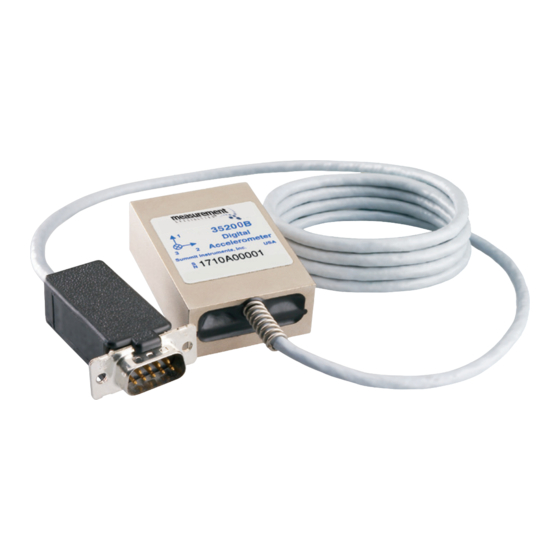
35200B
Uniaxial
Biaxial
Triaxial
Digital Accelerometer
User Configurable to ±70 g
Measurement Specialties, Inc.
2236 N. Cleveland-Massillon Rd.
Akron, Ohio 44333-1255 USA
(330) 659-3312 www.meas-spec.com
precisionsensors.meas-spec.com
Terminal Block
Male D-Shell
Connector
Accelerometer Connections
Pin
Description
Cable Wire
}
1
Analog Output 1+
Brown
twisted pair
2
Analog Output 2+
Red
}
3
Analog Output 3+
Orange
twisted pair
4
Signal -
Yellow
}
5
RS485-
Green
twisted pair
6
RS485+
Blue
}
7
Aux
Violet
twisted pair
8
+V s (Power)
Grey
9
Ground
White*
*connected to braided shield at D-shell pin
CAUTION
Improper wiring, particularly Power, may cause
permanent damage and void the warranty.
Pins other than +V s should not exceed 5 V.
Specifications*
Parameter
Min
Typical
Accelerometers Full Scale Range
Option R070
Option R050
Option R035
Sensitivity Drift 25°C to T
or T
min
max
Zero g Drift 25°C to T
or T
min
max
Alignment
Transverse Sensitivity
Nonlinearity
Frequency Response
0
Noise Density
Option R070
Option R050
Option R035
Temperature Sensor
Range
-55
Resolution
Accuracy
Digital Signal Processor
Sensor Scan Rate
Analog Outputs
Voltage Swing
0.25
Impedance to Analog-
100
Nonlinearity
Digital Output Word Size
Power Supply (V
)
s
Input Voltage Limits
-80
Input Voltage - Operating
+8.5
Input Current
Rejection Ratio
>120
Temperature Range (T
)
-40
a
Mass
Shock Survival - Sensor
-1500
Data subject to change without notice
*within one year of calibration
User configurable low-pass filter 3 dB cutoff (number poles configurable)
†
Mounting Instructions
►Use two 3.0 mm x 0.5 mm thread machine screws to attach
to the bottom or rear 15200B/25200B/35200B mount faces
[recommended torque 5 lbf-in (0.56 N.m)]. Be careful not to
bottom screws in tapped holes as this can strip threads.
►A light film of oil or silicone grease can be used to enhance
contact between mounting surfaces.
►A locking compound should be used on all threads to prevent
screws loosening due to vibrations.
0.167
0.354
0.494
0.354
0.354
0.354
[4,25]
[9,00]
[12,55]
[9,00]
[9,00]
[9,00]
0.354
X
[9,00]
0.354
1
3
1.437
3
[9,00]
1
[36,50]
2
0.354
2
[9,00]
0.187
[4,76]
0.689
2.049
[17,50]
[52,05]
Rear View
Bottom View
Max
Units
Measurement Specialties, Inc. warrants this product against defects
in materials and workmanship for a period of three years from date
±70
g
of shipment. During the warranty period, Measurement Specialties
±50
g
±35
g
will, at its option, either repair or replace products which prove to
±0.5
%
be defective.
±1
g
±3.0
degrees
This warranty does not apply to defects or damage resulting from:
0.25
%
• Improper installation or maintenance
0.2
2
% FSR
• Customer supplied software or interfacing
400
Hz
†
• Unauthorized modification or misuse
1.8
3.5
mg/√Hz
• Operation outside of the product specifications
1.4
3
mg/√Hz
1.1
3
mg/√Hz
The warranty set forth above is exclusive and no other warranty,
125
°C
whether written or oral, is expressed or implied. Measurement
0.25
°C
±2
±3
°C
Specialties specifically disclaims the implied warranties of
merchantability and fitness for a particular purpose.
42,500
Hz
Some jurisdictions do not allow limitations on how long an implied
4.75
V
warranty lasts, so the above limitation or exclusion may not apply to
130
220
Ω
0.15
% FSR
you. However, any implied warranty of merchantability or fitness is
16
bits
limited to the three-year duration of this written warranty.
+80
V
+36
V
To obtain service during the warranty period, products must be
55
mA
returned, transportation prepaid, to Measurement Specialties.
dB
+85
°C
78
grams
15200B/25200B/35200B Rev. 8/14/13
+1500
g
Connection to a PC using MEAS Adapters
Connect a 15200B/25200B/35200B to a 35250A, and connect a PC
COM port to the other side of the 35250A using the cable provided.
(If connecting to a PC with only a USB port, an RS232 to USB cable
will be needed). Plug power supply into wall and plug into power
jack on side of 35250A. Accelerometer should then be ready for use.
15200B
25200B
3 mm x 0,5 mm Thread
35200B
0.138 [3,50] Deep
Accelerometer
16 Places on 2 Views
0.575
0.240
[14,60]
[6,10]
Spring and cable
added with
cable options
Dimensions in inches [mm]
Three-Year Limited Warranty
Exclusions
Limitations
Warranty Service
120VAC
Power
Supply
1.3mm
Plug/Jack
COM
Port
35250A
Cable
Adapter
9 Pin
9 Pin
9 Pin
D-Subs
D-Subs
D-Subs
Optional Analog
Monitoring Port
PC
Advertisement
Table of Contents

Related Manuals for Measurement Computing 15200B


Summary of Contents for Measurement Computing 15200B
- Page 1 User configurable low-pass filter 3 dB cutoff (number poles configurable) † Connection to a PC using MEAS Adapters Connect a 15200B/25200B/35200B to a 35250A, and connect a PC COM port to the other side of the 35250A using the cable provided. Mounting Instructions (If connecting to a PC with only a USB port, an RS232 to USB cable ►Use two 3.0 mm x 0.5 mm thread machine screws to attach...
- Page 2 How to Use the 15200B / 25200B / 35200B Typical Settings Changed with ICU Installing and Using ICU as an Analog Sensor ►First, uninstall any previous versions of ICU that may be ►Accelerometer ranges (Range Hi and Range Lo) installed, then download Instrument Configuration Utility ►If...
Need help?
Do you have a question about the 15200B and is the answer not in the manual?
Questions and answers