
Subscribe to Our Youtube Channel
Related Manuals for CDA HNE8FR


Summary of Contents for CDA HNE8FR
- Page 1 HNE8FR Induction hob with built in extractor Installation, use and maintenance www.cda.eu...
-
Page 2: Table Of Contents
Contents: Important information Important safety warnings/notes Important notes for safety, use and care Pacemaker and active implants information Important safety warnings Saving energy Cooking on induction (and pan compatibility) Hob layout Using your hob(s) Booster function Operating time limiter Timer/minute minder Setting the timer on multiple zones Setting the minute minder Pause function... - Page 3 Contents: 28 Troubleshooting - extractor 30 Installation - preparation 32 Installation diagrams Flush or inset installation of the hob Extractor system dimensions 35 Installation - assembly 39 Ducting 40 Connecting the ducting Mains electricity connection 42 Wiring box connections Extractor plug information 46 Energy efficiency information IMPORTANT: IF YOUR EXTRACTOR DOES NOT APPEAR TO BE WORKING AT ANY TIME, PLEASE ENSURE THAT THE RED POWER...
- Page 4 Appliance information: Please enter the details on the appliance rating plate below for reference, to assist CDA Customer Care in the event of a fault with your appliance and to register your appliance for guarantee purposes. Appliance Model...
-
Page 5: Important Information
(EMC) 2014/30/EU. Parts intended to come into contact with food conform to 1935/2004/EC. IMPORTANT INFORMATION FOR CORRECT DISPOSAL OF THE PRODUCT IN ACCORDANCE WITH EC DIRECTIVE 2012/19/EU. At the end of its working life, the product must be taken to a special local authority waste collection centre or to a dealer providing appliance recycling services. - Page 6 To avoid interference between your hob and a pacemaker, your pacemaker must be designed and programmed in compliance with the regulations that apply to it. As such, CDA guarantee only that our product is compliant. With regard to the compliance of the pacemaker or any potential incompatibility, you should obtain information from the manufacturer or your attending physician.
-
Page 7: Saving Energy
Important • Do not use the hob if the glass surface is cracked or damaged to prevent the risk of electric shock. Disconnect it from the power supply. • Ensure that the power cable of a connected electrical appliance near the hob is not in contact with the cooking zones. •... -
Page 8: Cooking On Induction (And Pan Compatibility)
Cooking on Induction The principle of induction cooking is based on magnetic effect. When you put your cookware on an induction zone and switch it on, the electronic boards in the hob produce induced currents in the base of the cookware and instantly raise its temperature. This heat is then transferred to the food inside the cookware. -
Page 9: Hob Layout
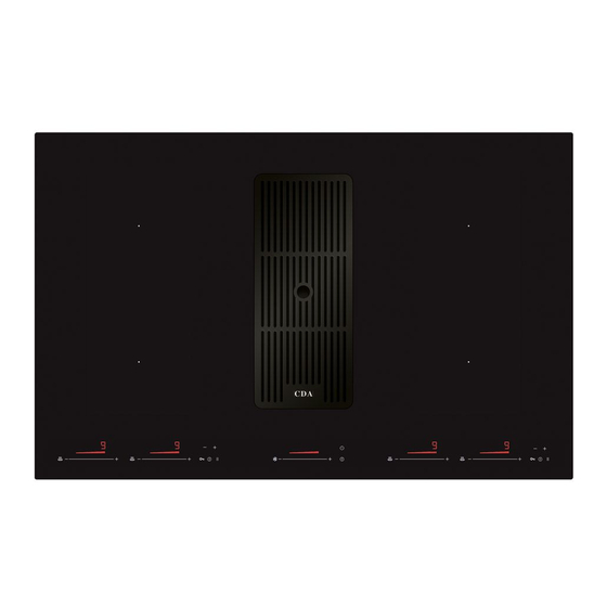
Hob layout Zones: 1. Rear left 2.1 - 3.7kW 2. Front left 2.1 - 3.7kW 3. Rear right 2.1 - 3.7kW 4. Front right 2.1 - 3.7kW Fig. 1 Please note: The octagonal zone coils and dotted line markings in Fig. 1 are visible for informational purposes. -
Page 10: Using Your Hob(S)
Using your hob(s) To switch a hob on • To switch the power on, touch and hold the on/off sensor (9) approximately one second. The hob will beep and all cooking zone indicators will show ‘0’. The inductor modules will click faintly when turning the hob on (and off). -
Page 11: Booster Function
Booster function The hob is equipped with a booster function on all zones, allowing a higher power level than the maximum for approximately ten minutes. To activate the booster on a zone • Regardless of whether a power level is already set, simply touch the '+' symbol at the end of the slider for the relevant zone. -
Page 12: Operating Time Limiter
It is normal for a high pitched whirring noise to begin whilst the booster function is in use. This is the cooling fan inside the hob keeping the internal components as cool as possible. If a pot is removed from the cooking zone whilst the booster function is in use, the ten minute countdown should continue. -
Page 13: Timer/Minute Minder
Timer/Minute minder The hob is equipped with a timer that allows a finish time to be set for the end of cooking on any zone, between a minimum of 1 minute and a maximum of 119 minutes. This timer can be used separately for each zone, and the timer activity indicator (3) will illuminate faintly on each zone for which it is set and remain brightest on the first zone to end. - Page 14 zone the subsequent timer adjustment will affect. • Next, use the timer plus setting sensor (7) and the timer minus setting sensor (5) to set the desired timer duration. The timer is increased in 1 minute increments per each press of the + or - sensors.
- Page 15 minus and plus setting sensors (5 & 7) repeatedly to cycle through the zones until the timer activity indicator for the desired zone is illuminated brightly. • Reduce the time on the timer display (6) to 0.00 using the timer minus setting selector (5).
-
Page 16: Pause Function
Pause function The hob is equipped with a pause function that allows the user to suspend the hob's operation for a brief period of time and to easily continue cooking when convenient from the previously assigned settings. This is particularly useful when your attention is drawn from the hob, i.e. -
Page 17: Keep Warm Function
Once power has been restored the pause function LED will flash to indicate that the previous settings can still be restored. Keep warm function Each zone is equipped with a keep warm function that is designed to keep food at a stable temperature. This allows for the serving of food to be delayed and also for the melting of butter or chocolate. -
Page 18: Bridge Function
will be displayed when the 94°C heating level is active. The cooking zone indicator will display a To deactivate the keep warm function • Touch the relevant zone’s keep warm function sensor (12) the required number of times until the display reads ‘0’ again. Please note: Any zones that are still hot to the touch will display an ' ' provided the mains power supply is not interrupted. -
Page 19: Control Lock
Please note: Pans placed on bridged zones must always cover the vertical markings (II) on the zones; Control lock To prevent accidental use or inadvertent setting changes, the hob has a control lock which disables controls. Disconnecting the appliance from the mains will deactivate the control lock. -
Page 20: Residual Heat Indicators
To activate the safety key lock Turn on the hob but do not set a power level on any zone. Touch the lock sensor and the pause sensor simultaneously, release them and touch the lock sensor again. This must be done within 10 seconds of switching the hob on. -
Page 21: Auto-Heat Function
the hob, yet the hob zone(s) may still be hot so extra care must be taken. Auto-heat function Every zone is equipped with an auto-heat function, which reduces the warming up time for the zone. To activate the auto-heat function on a zone •... -
Page 22: Using Your Extractor
Using your extractor Fig.4 To switch the extractor on and adjust the speed • To switch the power on, touch and hold the on/off sensor approximately one second. The extractor should turn on at the default speed of 2 (represented by 2 solid red bars). •... -
Page 23: Efficient Use Of Your Hob
Efficient use of your hob The hob is equipped with zones designed to accommodate most shapes and sizes of pan. For best results, only use pans with flat bottoms. The most efficient use of the hob is shown below, where the pan and zone are correctly chosen. -
Page 24: Care And Maintenance
It is very important that the pans used on the hob are made of a suitable material and have the correct type of base. The base of the pan and the hob top must be clean before use to prevent any scratches on the hob top. -
Page 25: Cleaning Guide
2. Check that the mains supply has not been switched off. 3. Check that the fuse in the spur has not blown. In the event of a fault with the hob please advise CDA Customer Care. Contact CDA Customer Care... -
Page 26: Troubleshooting - Hob
The hob is not working and the The electronics touched too briefly (less again and for longer. display shows a non-standard are not functioning Call CDA Customer Care than a second). graphic correctly Sensor fields do not The hob is not working and the... - Page 27 Should any error code show on the zone displays, or the above steps not resolve an issue, please contact CDA Customer Care for assistance. Contact details are on page 25. IMPORTANT - PLEASE NOTE: In the event of any breakage, crack or cracking –...
-
Page 28: Troubleshooting - Extractor
Troubleshooting - extractor If your extractor is not working: Check that the mains supply has not been switched off. Check that the fuse in the spur has not blown. Check that the red power switch on the wiring box has not been turned off (page 3). - Page 29 4 hours of continued use if no settings have been changed. If any of the potential resolutions in this guide do not resolve your issue, please contact CDA Customer Care using the contact details below. Contact CDA Customer Care...
-
Page 30: Installation - Preparation
Installation - preparation The installation of this product must be carried out by suitably qualified personnel. Always wear adequate PPE (Personal Protective Equipment) for the tasks at hand. This product may have sharp edges. This is a 2 person minimum install. Unpacking the appliance: Take care not to drop any parts. - Page 31 900mm. The minimum height of any adjacent units (including light pelmets) is 400mm, unless they are manufactured from a material resistant to fire (steel, for example). Furniture requirements: We recommend fitting this appliance within a 900mm or 1000mm base unit. Ensure that the unit you fit the appliance within does not hamper or foul the ventilation fans on the underside of the hob(s).
- Page 32 205mm min. 50 mm min. 50 mm 20 mm 20 mm Fig.6 Rear Wall Adjacent vertical surface (cupboard etc. - Measurement applicable to both sides.) Cut-out Min. Front edge of worktop Fig.7 410mm 410mm Fig.8...
-
Page 33: Flush Or Inset Installation Of The Hob
Flush or inset installation of the hob: Depending on whether you would like the hob to be inset or flush fit into the worktop, the cutout requirements are slightly different: Inset installation 5.5 mm 2 mm Flush installation 2 mm 5.5 mm 6 mm 750 490... -
Page 34: Extractor System Dimensions
Installation - extractor system dimensions min. 50... -
Page 35: Installation - Assembly
Installation - assembly Always wear adequate PPE (Personal Protective Equipment) for the tasks at hand. This product may have sharp edges. Lay a clean, soft towel (or similar) somewhere smooth and flat. This will protect the hob and the surface below. Remove the hob, turn it upside down and place it on the towel. - Page 36 Apply the supplied hob seal to the whole of the underside of the hob as per Fig. 13. Do not leave gaps in the seal. Fit the hob into the worktop opening, taking care not to damage the appliance or the units/worktop.
- Page 37 Locate the motor box and attach the conduit chamber to it using the screws provided, as per Fig. 15. Loosely attach the chimney conduits to the base section, raise them up to the hob extractor outlet and fit them as though you were completing the conduit section install. Whilst another person supports the sections, ensure that everything is aligned and nothing is being strained or twisted.
- Page 38 Raise the upper conduit section and secure it to the airbox as per Fig. 18 on page 37. Secure all of the connection areas with the supplied tape as per Fig. 19. Fit the grease filters into the extractor aperture as per Fig.
-
Page 39: Ducting
IMPORTANT: Secure the metal wiring box (indicated in Fig. 22) at least 10cm above floor level and at least 65cm from gas appliances, heat sources and the hob/extractor surface of the appliance itself. Do not place near water inlets or outlets. Ducting The ducting used should be rigid pipe of a constant diameter and must be manufactured from fire retardant material, produced to BS... -
Page 40: Connecting The Ducting
Connecting the ducting You can use either the air outlet on the right of the motor box or the air outlet on the left, depending upon the install requirements. If you need to change the position of the outlet flange, cover the exposed side with the blanking plate provided and four screws. -
Page 41: Mains Electricity Connection
Mains electricity connection Warning! This appliance must be earthed. • The appliance must be connected by a qualified electrician, who is a member of the N.I.C.E.I.C. and who will comply with the I.E.T. and local regulations. • When installing this product we recommend you seek the help of another individual. -
Page 42: Wiring Box Connections
• Should the mains cables be damaged or need to be replaced, contact CDA Customer Care to arrange a service visit. Contact details are on the rear cover of this manual. Wiring box connections: Fig. -
Page 43: Extractor Plug Information
Extractor plug information Warning! This appliance must be earthed. The mains lead of this appliance has been fitted with a BS 1363A 3 amp fused plug. To change a fuse in this type of plug, follow the steps below: 1. Remove the fuse cover (A) and fuse (B). 2. - Page 44 How to connect an alternative plug If the fitted plug is not suitable for your socket outlet, then it should be cut off and disposed of safely to avoid the risk of electric shock. Ensure there is no power to the appliance if/when you do this! A suitable alternative plug of at least 3 amp rating to BS 1363 should be used.
- Page 45 NOTES:...
-
Page 46: Energy Efficiency Information
Energy E ciency Information Attribute Symbol Value Units CDA model HNE8FR Hobs Type of hob Built in Number of cooking zones and/or areas Heating technology (induction cooking Induction zones and cooking areas, radiant cooking zones cooking zones, solid plates) For circular cooking zones or area: Ø... - Page 47 Energy E ciency Information Attribute Symbol Value Units i t n c i f HNE8FR Extractor Annual Energy Consumption 61.6 Hood Time increase factor 27.1 (B) Hood 56.9 (B) Hood 336.2 Point Point Maximum airflow Measured electric power at Best 168.9...
- Page 48 For more information please contact: The Sales Department on 01949 862 010 or email sales@cda.eu Customer Care Department. The CDA Group Ltd, Harby Road, Langar, Nottinghamshire, NG13 9HY 01949 862 012 F: 01949 862 003 E: customer.care@cda.eu www.cda.eu...
Need help?
Do you have a question about the HNE8FR and is the answer not in the manual?
Questions and answers