
Related Manuals for Hinkley HOVER FLUSH 900872FGT-LWD


Summary of Contents for Hinkley HOVER FLUSH 900872FGT-LWD
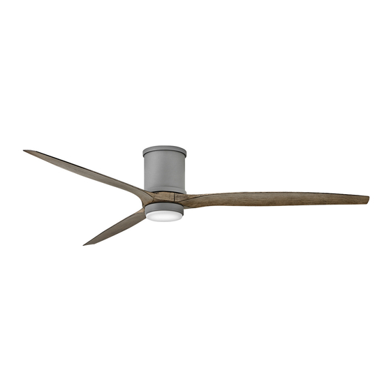
- Page 1 72" HOVER FLUSH ™ INDOOR / OUTDOOR LED FAN DC MOTOR CEILING FAN INSTRUCTION MANUAL...
- Page 2 SO WE’RE HERE IF YOU HAVE A QUESTION, NEED SOME HELP OR WANT TO CHAT ABOUT OUR PRODUCTS. SEND SUGGESTIONS OUR WAY TOO—WE’RE ALWAYS LOOKING TO MAKE YOUR EXPERIENCE WITH HINKLEY A POSITIVE ONE. > SERVICE@HINKLEY.COM > 800.HINKLEY > LET’S SEE THAT HINKLEY STYLE @HINKLEY...
-
Page 3: Table Of Contents
HANGING THE FAN ENERGY GUIDE ELECTRICAL CONNECTIONS SPECIFICATIONS FINISHING THE INSTALLATION SMART BY BOND INSTALLING OF THE BLADES WARNING: Read and follow these instructions carefully and be mindful of all warnings shown throughout. ©2021 Hinkley Lighting, Inc. | hinkley.com |... - Page 4 If the battery compartment does not close securely, stop using the product and keep it away from children. If you think batteries might have been swallowed or placed inside any part of the body, seek immediate medical attention. | hinkley.com...
-
Page 5: Important Safety Precautions
These factors must be supplied by the person(s) installing, caring for and operating the unit. TOOLS & MATERIALS REQUIRED • PHILLIPS SCREWDRIVER • FLAT SCREWDRIVER • WRENCH OR PLIERS • WIRE CUTTER • STEPLADDER • WIRING SUPPLIES AS REQUIRED BY ELECTRICAL CODE ©2021 Hinkley Lighting, Inc. | hinkley.com |... -
Page 6: Unpacking Your Fan
flat washers, wire nuts), Blade to Motor Screws w/Lock MH900872Fxx Washers, Balance Kit, Safety cable hardware NOTE: Design of parts shown above may look slightly different for (wood screw, flat washer) your specific model of fan. XX=FAN FINISH | hinkley.com... -
Page 7: Preparation
The outlet box must be able to support a minimum of 35 pounds. Screws Attach mounting bracket to outlet box using screws provided with the outlet box. Fig. 1 ©2021 Hinkley Lighting, Inc. | hinkley.com |... -
Page 8: Hanging The Fan
Firmly Safety cable clamp tighten screw in the clamp. Cut off excess cable. (Fig. 2) Safety cable loop You are now ready to make the electrical connections. Wood screw and washer Safety cable Fig. 2 | hinkley.com... -
Page 9: Electrical Connections
Connect the WHITE receiver neutral wire to the WHITE building neutral wire. Connect the COPPER building ground wire to the 4 YELLOW / GRAY GREEN ground wires from the fan and receiver. YELLOW YELLOW GRAY Fig. 1 ©2021 Hinkley Lighting, Inc. | hinkley.com... -
Page 10: Finishing The Installation
4 tabs on the decorative ring. Once lined up, slide the decorative ring and secure it to the top of the fan motor until snug. (Fig. 2) Mounting bracket Screws Fig. 1 Studs Decorative ring motor Fig. 2 hinkley.com... - Page 11 Repeat procedure for remaining blades. Make sure screws are TIGHT! Loose motor screws can contribute to unnecessary hum during operation. Blades Blade support plates Screws Fig. 1 INSTALLING THE ADAPTER PLATE Mounting hub Adapter plate Fig. 1 Screws ©2021 Hinkley Lighting, Inc. | hinkley.com |...
- Page 12 Raise glass shade up against adapter plate and secure it Fig. 1 to the fan by turning the glass shade clockwise until snug. DO NOT OVERTIGHTEN. Restore power and your light kit is ready for operation. LED assembly Glass shade Fig. 2 | hinkley.com...
- Page 13 Remote transmitter will be held in place with built in magnets. Cradle B Wall plate Plastic Face plate anchor Transmitter Outlet box Wall plate Cradle A Face plate Transmitter Wall Fig. 1 HIRO Control System Fig. 2 ©2021 Hinkley Lighting, Inc. | hinkley.com |...
- Page 14 Power lead to the fan is connected to the remaining switch lead. (Fig. 4) Attach the cradle A to the wall switch box using the supplied hardware. Attach the multi-gang faceplate to the switch set in the wall outlet box. Cradle A of Hinkley switch will fit in any standard decora face plate.
- Page 15 NOTE: A single fan can be controlled with as many as 3 wall controls in one room. Every control will need to repeat the pairing process based on instructions above and all controls must be within 30 feet of the fan. ©2021 Hinkley Lighting, Inc. | hinkley.com |...
- Page 16 An UPWARD airflow moves warmer air off the ceiling area as shown in Figure 4. This allows you to set your heating unit on a cooler setting without affecting your comfort. SUMMER MODE WINTER MODE (COUNTERCLOCKWISE DIRECTION) (CLOCKWISE DIRECTION) Fig. 3 Fig. 4 | hinkley.com...
- Page 17 2. If the blade wobble is still noticeable, interchanging two adjacent (side by side) blades can redistribute the weight and possibly result in smoother operation. 3. Check to assure all dowrods to motor hardware and/or hanger ball are tight. 4. Make sure ceiling box is secure. ©2021 Hinkley Lighting, Inc. | hinkley.com |...
- Page 18 • Your cost depends on rates and use • Energy Use: 19 Watts RPMs All estimates based on typical use, excluding lights ftc.gov/energy Airflow Shown Is a Weighted Average of High and Low Cubic Feet per Minute Based on Close to Ceiling | hinkley.com...
- Page 19 Wait 10 seconds. f) Hold down the Power button on the transmitter you wish to pair. In addition to the included wall control, you can control your Hinkley The fan light should flash three times and the motor spin up for fan through the Bond app.
- Page 20 HINKLEY IS PROUD TO PROVIDE YOU WITH CEILING FAN PRODUCTS THAT ENHANCE YOUR SPACE WITH COMFORT, PURPOSE AND STYLE. AS A FAMILY COMPANY, WE ARE COMMITTED TO DESIGN, PERFORMANCE AND QUALITY, AND WHAT’S IMPORTANT TO YOU IS PARAMOUNT TO US.
- Page 21 GLOBAL HEADQUARTERS 33000 Pin Oak Parkway | Avon Lake, Ohio 44012 T (440) 653 5500 | F (440) 653 5555 | hinkley.com...
- Page 22 72" HOVER FLUSH ™ VENTILADOR LED INTERIOR / EXTERIOR DC MOTOR MANUAL DE INSTRUCCIONES PARA VENTILADORES DE TECHO...
- Page 23 Si no está familiarizado o no se siente cómodo con el cableado, comuníquese con un electricista calificado. Si necesita asistencia adicional o tiene alguna pregunta, comuníquese con nosotros. Para obtener información sobre la garantía, visite hinkley.com.
- Page 24 HANGING THE FAN ENERGY GUIDE ELECTRICAL CONNECTIONS SPECIFICATIONS FINISHING THE INSTALLATION SMART BY BOND INSTALLING OF THE BLADES WARNING: Read and follow these instructions carefully and be mindful of all warnings shown throughout. ©2021 Hinkley Lighting, Inc. | hinkley.com |...
- Page 25 Si el compartimento de la batería no se cierra de forma segura, deje de usar el producto y manténgalo alejado de los niños. Si cree que las baterías pueden haber sido ingeridas o colocadas dentro de cualquier parte del cuerpo, busque atención médica de inmediato. | hinkley.com...
- Page 26 HERRAMIENTAS Y MATERIALES REQUERIDOS • DESTORNILLADOR PHILLIPS • DESTORNILLADOR PLANO • LLAVE O ALICATES • CORTADOR DE CABLES • ESCALERA DE TIJERA • SUMINISTROS DE CABLEADO SEGÚN REQUERIDO POR CÓDIGO ELÉCTRICO ©2021 Hinkley Lighting, Inc. | hinkley.com |...
- Page 27 MH900872Fxx Kit de equilibrio, Hardware del cable de seguridad (tornillo para madera, arandela plana) NOTA: El diseño de las piezas que se muestran arriba puede parecer un poco diferente para su modelo específico de ventilador. XX=ACABADO DEL VENTILADOR | hinkley.com...
- Page 28 35 libras. Empulgueras Fije el soporte de montaje a la caja de salida con los tornillos que se proporcionan con la caja de salida. Fig. 1 ©2021 Hinkley Lighting, Inc. | hinkley.com |...
- Page 29 Apriete firmemente el tornillo de la abrazadera. Corte el Bucle de cable de seguridad cable sobrante. (Figura 2) Ahora está listo para realizar las conexiones eléctricas. Tornillo y arandela para madera Cable de seguridad Fig. 2 | hinkley.com...
- Page 30 Conecte el cable neutro BLANCO del receptor al cable neutro BLANCO del edificio. Conecte el cable de tierra del edificio de COBRE a los 4 cables de tierra GRIS AMARILLO / VERDE del ventilador y el receptor. AMARILLA ROJA ROJA AMARILLA GRIS Admirador Fig. 1 ©2021 Hinkley Lighting, Inc. | hinkley.com...
- Page 31 4 pestañas del anillo decorativo. Una vez alineados, deslice el anillo decorativo y asegúrelo a la parte superior del motor del ventilador hasta que quede ajustado. (Figura 2) Soporte de montaje Empulgueras Fig. 1 Espárragos Anillo decorativo Motor del ventilador Fig. 2 hinkley.com...
- Page 32 Cuchillas Placas de soporte de la hoja Empulgueras Fig. 1 INSTALACIÓN DE LA PLACA ADAPTADORA Hub de montaje Placa adaptadora Empulgueras Fig. 1 ©2021 Hinkley Lighting, Inc. | hinkley.com |...
- Page 33 NO APRIETE DEMASIADO. Restaure la energía y su kit de luz estará listo para funcionar. Montaje de LED Pantalla de vidrio Fig. 2 | hinkley.com...
- Page 34 El transmisor remoto se mantendrá en su lugar con imanes incorporados. placa de pared Cuna B Placa Ancla de Caja de salida frontal plastico Placa de Transmisora pared Cuna A Placa frontal Transmisora Pared Fig. 1 Fig. 2 Sistema de control HIRO ©2021 Hinkley Lighting, Inc. | hinkley.com |...
- Page 35 Fije la base A a la caja de interruptores de pared utilizando los accesorios suministrados. Conecte la placa frontal de varios grupos al interruptor en la caja de salida de la pared. La base A del interruptor Hinkley encajará en cualquier placa frontal decora estándar. Fig. 4 El transmisor remoto se mantendrá...
- Page 36 3 controles de pared en una habitación. Cada control Fig. 2 deberá repetir el proceso de emparejamiento según las instrucciones anteriores y todos los controles deben Sistema de control HIRO estar a menos de 30 pies del ventilador. ©2021 Hinkley Lighting, Inc. | hinkley.com |...
- Page 37 Un fl ujo de aire HACIA ARRIBA mueve el aire más caliente del área del techo como se muestra en la Figura 4. Esto le permite configurar su unidad de calefacción en una configuración más fría sin afectar su comodidad. MODO VERANO MODO INVIERNO (DIRECCIÓN EN SENTIDO (SENTIDO DE LAS AGUJAS ANTIHORARIO) DEL RELOJ Fig. 3 Fig. 4 | hinkley.com...
- Page 38 3. Verifique que todas las varillas de los accesorios del motor y / o la bola de suspensión estén apretadas. 4. Asegúrese de que la caja del techo esté segura. ©2021 Hinkley Lighting, Inc. | hinkley.com |...
- Page 39 Todas las estimaciones se basan en el uso típico, excluyendo la luz. Amplificadores ftc.gov/energy 0.38 0.04 El flujo de aire que se muestra es un promedio ponderado de pies cúbicos altos y bajos por minuto basado en Downrod RPMs | hinkley.com...
- Page 40 OPCIONES DE VENTILADOR INTELIGENTE DE HINKLEY: Además del control de pared incluido, puede controlar su ventilador Hinkley a través de la aplicación Bond. • Para usar la aplicación, descárguela gratis de App Store o Google Play. • Abra la aplicación para crear su cuenta. También puede iniciar sesión con •...
- Page 41 HINKLEY SE ENCUENTRA ORGULLOSO DE PROPORCIONARLE PRODUCTOS PARA VENTILADORES DE TECHO QUE MEJORAN SU ESPACIO CON COMODIDAD, PROPÓSITO Y ESTILO. COMO EMPRESA FAMILIAR, ESTAMOS COMPROMETIDOS CON EL DISEÑO, EL RENDIMIENTO Y LA CALIDAD, Y LO QUE ES IMPORTANTE PARA USTED ES PARAMOUNT PARA NOSOTROS.
- Page 42 GLOBAL HEADQUARTERS 33000 Pin Oak Parkway | Avon Lake, Ohio 44012 T (440) 653 5500 | F (440) 653 5555 | hinkley.com...
- Page 43 72" HOVER FLUSH ™ VENTILATEUR LED INTÉRIEUR / EXTÉRIEUR DC MOTOR MANUEL D'INSTRUCTIONS POUR LES VENTILATEURS DE PLAFOND...
- Page 44 NOUS SOMMES ICI SI VOUS AVEZ UNE QUESTION, BESOIN D'UNE AIDE OU VOULEZ CHAT SUR NOS PRODUITS. ENVOYER DES SUGGESTIONS NOTRE FAÇON AUSSI - NOUS CHERCHONS TOUJOURS À FAIRE DE VOTRE EXPÉRIENCE AVEC HINKLEY UNE POSITIVE. > SERVICE@HINKLEY.COM > 800.HINKLEY >...
- Page 45 SUSPENSION DU VENTILATEUR CARACTÉRISTIQUES CONNECTIONS ELECTRIQUES INTELLIGENT PAR LIEN FIN DE L'INSTALLATION INSTALLATION DES LAMES ATTENTION Lisez et suivez attentivement ces instructions et tenez compte de tous les avertissements affichés tout au long. ©2021 Hinkley Lighting, Inc. | hinkley.com |...
-
Page 46: Instructions Générales D'installation Et
Si le compartiment des piles ne se ferme pas correctement, arrêtez d'utiliser le produit et tenez-le hors de portée des enfants. Si vous pensez que des piles ont pu être avalées ou placées à l'intérieur de n'importe quelle partie du corps, consultez immédiatement un médecin. | hinkley.com... -
Page 47: Précautions De Sécurité Importantes
être intégrés à ce produit. Ces facteurs doivent être fournis par la ou les personnes installant, prenant soin et utilisant l'appareil. OUTILS ET MATÉRIAUX REQUIS • TOURNEVIS CRUCIFORME • TOURNEVIS PLAT • CLÉ OU PINCE • COUPE-FIL • ESCABEAU • FOURNITURES DE CÂBLAGE COMME REQUIS PAR LE CODE ÉLECTRIQUE ©2021 Hinkley Lighting, Inc. | hinkley.com |... -
Page 48: Déballage De Votre Ventilateur
MH900872Fxx rondelles de blocage, Trousse d'équilibre, Matériel de câble de sécurité REMARQUE : La conception des pièces illustrées ci-dessus peut sembler (vis à bois, rondelle plate) légèrement différente pour votre modèle spécifique de ventilateur. XX=FINITION VENTILATEUR | hinkley.com... -
Page 49: Installation Du Support De Suspension
La boîte de sortie doit pouvoir supporter un minimum de 35 livres. Fixez le support de montage à la boîte de sortie à l'aide des vis fournies avec la boîte Des vis de sortie. Fig. 1 ©2021 Hinkley Lighting, Inc. | hinkley.com |... -
Page 50: Suspension Du Ventilateur
Serrez fermement la vis dans la Serre-câble de sécurité pince. Coupez le surplus de câble. (Fig. 2) Vous êtes maintenant prêt à effectuer les branchements électriques. Boucle de câble de sécurité Vis à bois et rondelle Câble de sécurité Fig. 2 | hinkley.com... -
Page 51: Connections Electriques
Connectez le fil neutre BLANC du récepteur au fil neutre BLANC du bâtiment. Connectez le fil de terre du bâtiment en CUIVRE aux 4 fils de terre JAUNE/ GRIS VERT du ventilateur et du récepteur. JAUNE rouge rouge JAUNE GRIS Ventilateur Fig. 1 ©2021 Hinkley Lighting, Inc. | hinkley.com... -
Page 52: Fin De L'installation
4 languettes de l'anneau décoratif. Une fois aligné, faites glisser l'anneau décoratif et fixez-le au sommet du moteur du ventilateur jusqu'à ce qu'il soit bien ajusté. (Fig. 2) Support de montage Des vis Fig. 1 Goujons Bague décorative Moteur de ventilateur Fig. 2 hinkley.com... -
Page 53: Installation Des Lames
à un bourdonnement inutile pendant le fonctionnement. Lames Plaques de support de lame Des vis Fig. 1 INSTALLATION DE LA PLAQUE ADAPTATEUR Moyeu de montage Plaque adaptatrice Fig. 1 Des vis ©2021 Hinkley Lighting, Inc. | hinkley.com |... -
Page 54: Installation De L'ensemble Led Et Du Pare-Verre
NE PAS TROP SERRER. Rétablissez le courant et votre kit d'éclairage est prêt à fonctionner. Ensemble LED Abat-jour en verre Fig. 2 | hinkley.com... -
Page 55: Installation De La Commande Murale
L'émetteur à distance sera maintenu en place avec des aimants intégrés. Berceau B plaque murale Plaque Ancre en Boîte de sortie frontale plastique Émettrice Plaque murale Berceau A Plaque frontale Émettrice Fig. 1 Système de contrôle HIRO Fig. 2 ©2021 Hinkley Lighting, Inc. | hinkley.com |... - Page 56 Fixez la plaque frontale multi-gang à l'interrupteur situé dans la boîte de prise murale. Le berceau A de l'interrupteur Hinkley s'adaptera à n'importe quelle plaque frontale decora standard. L'émetteur à distance sera maintenu en place avec des aimants intégrés Fig.
-
Page 57: Opération
Fig. 2 Chaque commande devra répéter le processus d'appariement en fonction des instructions ci-dessus et Système de contrôle HIRO toutes les commandes doivent se trouver à moins de 30 pieds du ventilateur. ©2021 Hinkley Lighting, Inc. | hinkley.com |... - Page 58 Un flux d'air VERS LE HAUT déplace l'air plus chaud hors de la zone du plafond, comme illustré à la figure 4. Cela vous permet de régler votre unité de chauffage sur un réglage plus frais sans aecter votre confort. MODE ÉTÉ MODE ÉTÉ (SENS ANTI-HORAIRE) (SENS ANTI-HORAIRE) Fig. 3 Fig. 4 | hinkley.com...
-
Page 59: Entretien Et Nettoyage
éventuellement améliorer le fonctionnement. 3. Assurez-vous que toutes les tiges de fixation de la quincaillerie du moteur et/ou de la boule de suspension sont bien serrées. 4. Assurez-vous que la boîte de plafond est sécurisée. ©2021 Hinkley Lighting, Inc. | hinkley.com |... - Page 60 0.38 0.04 Todas las estimaciones se basan en el uso típico, excluyendo la luz. ftc.gov/energy El flujo de aire que se muestra es un promedio ponderado de pies cúbicos altos y bajos por minuto basado en Downrod RPMs | hinkley.com...
-
Page 61: Intelligent Par Lien
Dans les 15 secondes suivant la mise sous tension, maintenez enfoncé le bouton Speed 1 de n'importe quel émetteur compatible pendant 20 secondes. d) Le voyant du ventilateur doit clignoter 5 fois et peut tourner à basse vitesse https://bondhome.io/app pendant 10 secondes. ©2021 Hinkley Lighting, Inc. | hinkley.com |... - Page 62 HINKLEY EST FIÈRE DE VOUS FOURNIR DES PRODUITS DE VENTILATEUR DE PLAFOND QUI AMÉLIORENT VOTRE ESPACE AVEC CONFORT, OBJECTIF ET STYLE. EN TANT QU'ENTREPRISE FAMILIALE, NOUS NOUS ENGAGEONS À CONCEVOIR, PERFORMANCE ET QUALITÉ, ET CE QUI EST IMPORTANT POUR VOUS EST PARAMOUNT POUR NOUS.
- Page 63 GLOBAL HEADQUARTERS 33000 Pin Oak Parkway | Avon Lake, Ohio 44012 T (440) 653 5500 | F (440) 653 5555 | hinkley.com...
Need help?
Do you have a question about the HOVER FLUSH 900872FGT-LWD and is the answer not in the manual?
Questions and answers