
Subscribe to Our Youtube Channel
Related Manuals for Hinkley VAIL FLUSH 902552FMW-LWD


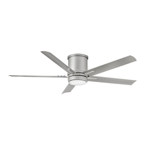
Summary of Contents for Hinkley VAIL FLUSH 902552FMW-LWD
- Page 1 52" VAIL FLUSH ™ INDOOR / OUTDOOR LED FAN DC MOTOR CEILING FAN INSTRUCTION MANUAL...
- Page 2 SO WE’RE HERE IF YOU HAVE A QUESTION, NEED SOME HELP OR WANT TO CHAT ABOUT OUR PRODUCTS. SEND SUGGESTIONS OUR WAY TOO—WE’RE ALWAYS LOOKING TO MAKE YOUR EXPERIENCE WITH HINKLEY A POSITIVE ONE. > SERVICE@HINKLEY.COM > 800.HINKLEY > LET’S SEE THAT HINKLEY STYLE @HINKLEY...
-
Page 3: Table Of Contents
HANGING THE FAN ENERGY GUIDE ELECTRICAL CONNECTIONS SPECIFICATIONS FINISHING THE INSTALLATION SMART BY BOND INSTALLING OF THE BLADES WARNING: Read and follow these instructions carefully and be mindful of all warnings shown throughout. ©2021 Hinkley Lighting, Inc. | hinkley.com |... -
Page 4: Instructions
If the battery compartment does not close securely, stop using the product and keep it away from children. If you think batteries might have been swallowed or placed inside any part of the body, seek immediate medical attention. | hinkley.com... -
Page 5: Important Safety Precautions
These factors must be supplied by the person(s) installing, caring for and operating the unit. TOOLS & MATERIALS REQUIRED • PHILLIPS SCREWDRIVER • FLAT SCREWDRIVER • WRENCH OR PLIERS • WIRE CUTTER • STEPLADDER • WIRING SUPPLIES AS REQUIRED BY ELECTRICAL CODE ©2021 Hinkley Lighting, Inc. | hinkley.com |... -
Page 6: Unpacking Your Fan
Blade to Blade Arm Screws w/Lock Washers, HW902152Fxx Blade to Motor Screws and Rubber Washers, Balance Kit, Safety cable hardware NOTE: Design of parts shown above may look slightly different for (wood screw, flat washer) your specific model of fan. XX=FAN FINISH | hinkley.com... -
Page 7: Preparation
The outlet box must be able to support a minimum of 35 pounds. Screws Attach mounting bracket to outlet box using screws provided with the outlet box. Fig. 1 ©2021 Hinkley Lighting, Inc. | hinkley.com |... -
Page 8: Hanging The Fan
Firmly Safety cable clamp tighten screw in the clamp. Cut off excess cable. (Fig. 2) Safety cable loop You are now ready to make the electrical connections. Wood screw and washer Safety cable Fig. 2 | hinkley.com... -
Page 9: Electrical Connections
Connect the WHITE receiver neutral wire to the WHITE building neutral wire. Connect the COPPER building ground wire to the 4 YELLOW / GRAY GREEN ground wires from the fan and receiver. YELLOW YELLOW GRAY Fig. 1 ©2021 Hinkley Lighting, Inc. | hinkley.com... -
Page 10: Finishing The Installation
4 tabs on the decorative ring. Once lined up, slide the decorative ring and secure it to the top of the fan motor until snug. (Fig. 2) Mounting bracket Screws Fig. 1 Studs Decorative ring motor Fig. 2 hinkley.com... -
Page 11: Installing The Adapter Plate
Repeat procedure for remaining blades. Make sure screws Blades are TIGHT! Loose motor screws can contribute to unnecessary Screws hum during operation. Blade arms Fig. 1 INSTALLING THE ADAPTER PLATE Mounting hub Adapter plate Screws Fig. 1 ©2021 Hinkley Lighting, Inc. | hinkley.com |... -
Page 12: Installing The Led Assembly And Glass Shade
Raise glass shade up against adapter plate and secure it Fig. 1 to the fan by turning the glass shade clockwise until snug. DO NOT OVERTIGHTEN. Restore power and your light kit is ready for operation. LED assembly Glass shade Fig. 2 | hinkley.com... -
Page 13: Installing The Wall Control
Remote transmitter will be held in place with built in magnets. Cradle B Wall plate Plastic Face plate anchor Transmitter Outlet box Wall plate Cradle A Face plate Transmitter Wall Fig. 1 HIRO Control System Fig. 2 ©2021 Hinkley Lighting, Inc. | hinkley.com |... - Page 14 Power lead to the fan is connected to the remaining switch lead. (Fig. 4) Attach the cradle A to the wall switch box using the supplied hardware. Attach the multi-gang faceplate to the switch set in the wall outlet box. Cradle A of Hinkley switch will fit in any standard decora face plate.
-
Page 15: Operation
NOTE: A single fan can be controlled with as many as 3 wall controls in one room. Every control will need to repeat the pairing process based on instructions above and all controls must be within 30 feet of the fan. ©2021 Hinkley Lighting, Inc. | hinkley.com |... - Page 16 An UPWARD airflow moves warmer air off the ceiling area as shown in Figure 4. This allows you to set your heating unit on a cooler setting without affecting your comfort. SUMMER MODE WINTER MODE (COUNTERCLOCKWISE DIRECTION) (CLOCKWISE DIRECTION) Fig. 3 Fig. 4 | hinkley.com...
-
Page 17: Care And Cleaning
2. If the blade wobble is still noticeable, interchanging two adjacent (side by side) blades can redistribute the weight and possibly result in smoother operation. 3. Check to assure all dowrods to motor hardware and/or hanger ball are tight. 4. Make sure ceiling box is secure. ©2021 Hinkley Lighting, Inc. | hinkley.com |... -
Page 18: Energy Guide
• Your cost depends on rates and use • Energy Use: 26 Watts RPMs All estimates based on typical use, excluding lights ftc.gov/energy Airflow Shown Is a Weighted Average of High and Low Cubic Feet per Minute Based on Close to Ceiling | hinkley.com... -
Page 19: Smart By Bond
Wait 10 seconds. f) Hold down the Power button on the transmitter you wish to pair. In addition to the included wall control, you can control your Hinkley The fan light should flash three times and the motor spin up for fan through the Bond app. - Page 20 HINKLEY IS PROUD TO PROVIDE YOU WITH CEILING FAN PRODUCTS THAT ENHANCE YOUR SPACE WITH COMFORT, PURPOSE AND STYLE. AS A FAMILY COMPANY, WE ARE COMMITTED TO DESIGN, PERFORMANCE AND QUALITY, AND WHAT’S IMPORTANT TO YOU IS PARAMOUNT TO US.
- Page 21 GLOBAL HEADQUARTERS 33000 Pin Oak Parkway | Avon Lake, Ohio 44012 T (440) 653 5500 | F (440) 653 5555 | hinkley.com...
Need help?
Do you have a question about the VAIL FLUSH 902552FMW-LWD and is the answer not in the manual?
Questions and answers