
Related Manuals for Hinkley 52 TREY


Summary of Contents for Hinkley 52 TREY
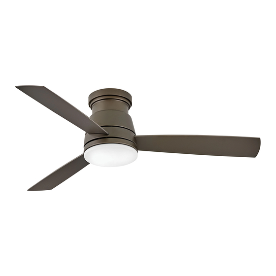
- Page 1 52" TREY ™ INDOOR / OUTDOOR LED FAN DC MOTOR CEILING FAN INSTRUCTION MANUAL...
- Page 2 SO WE’RE HERE IF YOU HAVE A QUESTION, NEED SOME HELP OR WANT TO CHAT ABOUT OUR PRODUCTS. SEND SUGGESTIONS OUR WAY TOO—WE’RE ALWAYS LOOKING TO MAKE YOUR EXPERIENCE WITH HINKLEY A POSITIVE ONE. > SERVICE@HINKLEY.COM > 800.HINKLEY > LET’S SEE THAT HINKLEY STYLE @HINKLEY...
-
Page 3: Table Of Contents
INSTALLING THE HANGING BRACKET TROUBLESHOOTING INSTALLING THE FAN ENERGY GUIDE ELECTRICAL CONNECTIONS SPECIFICATIONS FINISHING THE INSTALLATION SMART BY BOND BLADE ATTACHMENT WARNING: Read and follow these instructions carefully and be mindful of all warnings shown throughout. ©2019 Hinkley Lighting, Inc. | hinkley.com |... - Page 4 The fan can be made to work immediately after installation - the bearings are adequately charged with grease so that, under normal conditions, further lubrication should not be necessary for the life of the fan. To operate the reverse function on this fan, press the reverse button while the fan is running. | hinkley.com...
-
Page 5: Important Safety Precautions
These factors must be supplied by the person(s) installing, caring for and operating the unit. TOOLS & MATERIALS REQUIRED • PHILLIPS SCREWDRIVER • FLAT SCREWDRIVER • WRENCH OR PLIERS • WIRE CUTTER • STEPLADDER • WIRING SUPPLIES AS REQUIRED BY ELECTRICAL CODE ©2019 Hinkley Lighting, Inc. | hinkley.com |... -
Page 6: Unpacking Your Fan
Machine Screws Hardware Bag Bracket Mounting Hardware (wood screws, screws, lock washers, washers, wire nuts), Blade to Motor Screws w/Lock Washers, Balance Kit NOTE: Design of parts shown above may look slightly different for your specific model of fan. | hinkley.com... -
Page 7: Preparation
The bracket outlet box must be able to support a minimum of 35 pounds. Attach mounting bracket to outlet box using screws provided with the Screws outlet box. ©2019 Hinkley Lighting, Inc. | hinkley.com |... -
Page 8: Installing The Fan
Carefully lift fan motor assembly (without the blades) into position by hanging the motor assembly onto the hook from the ceiling mounting plate allowing it to hang freely . You are now ready to make the electrical connections. Outlet Box Motor | hinkley.com... -
Page 9: Electrical Connections
Also connect the two GREEN wires (from fan) to building WHITE (to motor) ground wire. RED (to motor) GRAY (to motor) YELLOW (to motor) YELLOW (motor) Receiver GRAY (motor) RED (motor) WHITE (motor) BLUE (motor) Fig. 1 Fig. 2 ©2019 Hinkley Lighting, Inc. | hinkley.com |... -
Page 10: Finishing The Installation
Raise the decorative ring up against the mounting bracket, the four supports inside the decorative ring should be placed against the four slots on mounting bracket, twist the decorative ring clockwise until snug (Fig. 2). Screws Mounting Bracket Fig. 1 Studs Decorative Ring motor Fig. 2 | hinkley.com... -
Page 11: Installing The Mounting Plate
Line up the two slotted holes with the two loose screws on the mounting hub located on fan motor. Re-install the third screw removed and tighten all three. Mounting Hub Screws Mounting Plate ©2019 Hinkley Lighting, Inc. | hinkley.com |... -
Page 12: Installing The Led Assembly And Glass Shade
Raise glass shade up against mounting plate and secure it to the fan by turning the glass shade clockwise until snug. DO NOT OVERTIGHTEN. Fig. 1 Restore power and your light kit is ready for operation. Mounting Plate Glass Shade Fig. 2 | hinkley.com... -
Page 13: Installing The Wall Control
Install the wall transmitter on the existing wall outlet box using the screws provided. Attached the wall plate with the mounting screws to finish the installation. (Fig. 2) Transmitter Decorative Wall Plate Fig. 2 ©2019 Hinkley Lighting, Inc. | hinkley.com |... -
Page 14: Operation
(suggested speed IV) Light button: Power switch This button is to control optional light. Switch the "D" and "ON" dip switch on the Fig. 2 front of transmitter to decide the light in "ON/OFF" or "Dimmable" condition. | hinkley.com... - Page 15 An UPWARD airflow moves warmer air off the ceiling area as shown in Figure 4. This allows you to set your heating unit on a cooler setting without affecting your comfort. SUMMER MODE WINTER MODE (COUNTERCLOCKWISE DIRECTION) (CLOCKWISE DIRECTION) Fig. 3 Fig. 4 ©2019 Hinkley Lighting, Inc. | hinkley.com |...
-
Page 16: Care And Cleaning
If the blade wobble is still noticeable, interchanging two adjacent (side by side) blades can redistribute the weight and possibly result in smoother operation. Check to assure all dowrods to motor hardware and/or hanger ball are tight. Make sure ceiling box is secure. | hinkley.com... -
Page 17: Energy Guide
SMART BY BOND HINKLEY SMART FAN OPTIONS: In addition to the included wall control, you can control your Hinkley fan through the Bond app. • To use the app, download it for free from the App Store or Google Play. - Page 18 HINKLEY IS PROUD TO PROVIDE YOU WITH CEILING FAN PRODUCTS THAT ENHANCE YOUR SPACE WITH COMFORT, PURPOSE AND STYLE. AS A FAMILY COMPANY, WE ARE COMMITTED TO DESIGN, PERFORMANCE AND QUALITY, AND WHAT’S IMPORTANT TO YOU IS PARAMOUNT TO US.
- Page 19 GLOBAL HEADQUARTERS 33000 Pin Oak Parkway | Avon Lake, Ohio 44012 T (440) 653 5500 | F (440) 653 5555 | hinkley.com...
Need help?
Do you have a question about the 52 TREY and is the answer not in the manual?
Questions and answers
When I tried to apply a new update, it always timed out. I tried it multiple times and it still does not work. The ****/light does not work and I had to take it offline and just use the manual switch to control it. How do solve this problem? (It only happened to my two 52" Trey fans. The 44" Trey and Hover Flush took their updates fine.
To fix the timeout issue when updating the Hinkley 52 TREY fans, follow these steps:
1. Switch off the power supply to the fan.
2. Restore power, then press and hold the “SET” button on the wall control for about 5 seconds and release.
3. Wait for the light kit (if installed) to flash twice and for the signal light on the wall control to turn on when a button is pressed—this confirms successful pairing.
4. Ensure all wall controls are within 30 feet of the fan and repeat the pairing process for each control.
If problems persist, check circuit fuses or breakers, confirm the wall control LED indicator lights up when pressing buttons, and ensure no more than two fans are on one wall control circuit.
This answer is automatically generated