
Related Manuals for Honeywell HUS-NVR-1032/6032-E


Summary of Contents for Honeywell HUS-NVR-1032/6032-E
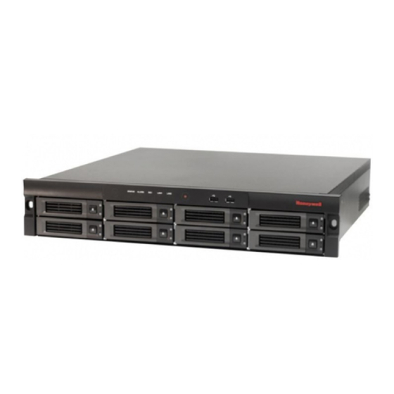
- Page 1 HUS-NVR-1032/6032-E HUS-NVR-1032/6032-C 32CH Network Video Recorder User Guide Document 800-13326 Rev. C...
-
Page 3: Table Of Contents
Contents About This Document ....................... 1 Overview of Contents ........................1 Special Fonts and Symbols ......................1 How to Use This Document ......................1 Introduction ..........................3 Features ............................. 3 Specifications ..........................4 Unpack Everything ........................5 Operating Keys ........................... 6 Front View .......................... - Page 4 Device Operation ........................ 32 Storage ..........................39 PTZ Control ........................43 Patrol ..........................44 Playback ........................... 48 Video Window Operation ....................48 Search and Back Up ......................... 50 Search Videos ........................50 Back Up Videos ........................52 View Log ........................... 54 Operation Log ........................
- Page 5 ............................81 ........................... 81 ......................... 81 ..........................82 ........................... 83 ........................... 83 ........................... 84 ........................... 85 ..........................86 ..........................86 ..........................87 ..........................89 ........................... 89 ....................90 ..........................90 ..........................90 ..........................90 ....................... 90 ....................... 90 ........................... 91 ........................
- Page 6 ........................106 ..........................106 ........................108 ........................... 109 ........................... 111 ........................... 118 ........................... 122 ..........................124 ..........................126 ........................127 ..........................129 ........................... 129 ........................... 130 ..........................133 ........................... 133 ........................... 134 ..........................137 ........................... 137 ........................... 137 ........................... 139 ..........................
- Page 7 Important Safety Instructions Before operating or installing the unit, read and follow all instructions. After installation, retain the safety and operating instructions for future reference. Electrical safety All installation and operation here should conform to local electrical safety codes. We assume no liability or responsibility for fires or electrical shock caused by improper handling or installation.
-
Page 9: About This Document
1 About This Document Thank you for purchasing the HUS-NVR-1032/6032-E (32 Channel Network Video Recorder) NVR. This user guide describes the features, installation, configuration and operation of the HUS- NVR-1032/6032-E, hereinafter referred to as “NVR”. Overview of Contents This user guide includes:... - Page 10 The manual has been reviewed and its accuracy is guaranteed. If there is any uncertainty or controversy, please refer to the final explanation of Honeywell. Honeywell does not take any responsibility for any consequences caused by the misunderstanding...
-
Page 11: Introduction
2 Introduction This chapter provides the features and specifications of the NVR and introduces its front and rear panel keys. Features Real-time Surveillance Supports real-time video on monitors via BNC, VGA and HDMI ports. Supports 16 channels (D1) / 8 channels (720P) / 4 channels (1080P) video signal and one channel audio signal decoded simultaneously. -
Page 12: Specifications
Introduction Video Storage Support RAID 0/1/5/6/10 (For Model 6032 only) 8 SATA HDD slots supporting hot plug. 2 e-SATA ports to connect e-SATA disk or specified disk array (recomended). Options on full HDD – Overwrite or Stop recording. Video recordings are stored in specialized formats to prevent the data from being altered and guarantee its integrity. -
Page 13: Unpack Everything
1 CVBS output, use BNC port (1.0V , 75 ); resolution: D1(4CIF), NTSC 704 * 480, PAL 704 * 576 Video Output 1 VGA output; resolution: 1280*1024/1920*1080 1 HDMI output; resolution: 1280*1024/1920*1080 Intercom Input/Output Reserved Audio Output 1 channel, RCA. Audio Compression G.711 1080P/720P/D1/4CIF/2CIF/CIF/QCIF 1~25 fps/PAL... -
Page 14: Operating Keys
Introduction Table 2-2 Accessory List Item Quantity HUS-NVR-1032/6032-E (32 channels network video recorder) Power cord 1 (Model1032) Power cord 2 (Model6032) Power adapter 2 (Model6032) GIGA LAN CABLE, 3000mm, CAT-5E Accessories box 6#-32 * 1/4 FM M6*12 PB Quality certification... -
Page 15: Rear View
Table 2-3 Name and Description of Keys (Front View) Symbol Name Function Hold it down for over 5 seconds to turn on the NVR. ON/OFF Switch When NVR is turned on, hold the button down over 5 seconds to turn NVR off. Panic Recording Hold it down for over 1 second to start/stop the panic recording. - Page 16 Introduction Model 1032 Table 2-4 Name and Description of Keys (Rear View) Name Description Power Input 1 Power input port 1 (Model 6032); (Model 6032); Power Switch Turn power on/off (Model 1032). (Model 1032) Power Input 2 Power input port 2 (Model 6032); (Model 6032);...
- Page 17 Grounding Screw For grounding 16, 17 Labels MAC address and rating plate Power Alarm Mute Turn on/off the power alarm sound Button...
-
Page 18: Installation And Connections
Installation and Connections 3 Installation and Connections This chapter explains how to install the HDD and connect the NVR to related devices. Attempting to open or disassemble the unit may expose you to dangerous voltage or other hazards and damage the unit. Make sure to ground the cabinet of the NVR! The grounding screw is on the rear panel of the unit. -
Page 19: Video And Audio Input/Output
3. Inset the HDD tray into the NVR. 4. Push the handle until it clicks into the lock. Video and Audio Input/Output Video Input The bandwidth for this NVR is 64Mbps; you can check the network information on the “System Status” screen. See “System Status”... -
Page 20: Alarm Input/Output
Installation and Connections “MIC In” on the rear panel of NVR is for local audio input of the intercom system; “Audio out 2” is for local audio output. Proper settings to Intercom audio enable using active and passive microphones. Earphones and active loudspeakers can be connected to the intercom output interface. -
Page 21: Specifications Of Alarm Output Relay
Specifications of Alarm Output Relay Table 3-2 Alarm Output Relay Model: HFD3 Rated switch capacity 2A 30VDC, 0.5A 125VAC Max switch power 62.5VA 60W Rating (Resistance load) Max switch voltage 250VAC, 220VDC Max switch current Open delay <4ms <4ms Close delay Example of Alarm Input/Output Connection This example is only for your reference. -
Page 22: Usb Connection
Installation and Connections USB Connection There are two USB ports (5V 500mA) on the front panel and one on the rear panel for connecting USB devices. To ensure the NVR runs properly, do not connect USB devices which consume a lot of power. e-SATA e-SATA port is used for connecting SATA disk or specified disk arrays (contact the technical support for the model number of HDD array). -
Page 23: Basic Operations
4 Basic Operations This chapter provides basic configuration and operation information of NVR. Note: Unless otherwise stated, the operations and screenshots in this book are based on the Model 1032. Make sure that HDDs have been installed and all the cables are connected properly before turning on the NVR. -
Page 24: Turning On
Basic Operations Table 4-1 Mouse Operation Keyboard Input Method Icon Keyboard Operations Number Click number/letter/symbol on the keyboard to input the corresponding character. Letter Click to clear the previous (lower case) character. Click to switch upper/lower case. Click to switch CN/EN input method Letter Click... -
Page 25: Default Accounts
After the system startup, the below figure is displayed: Figure 4-2 Language Setting Select “English” and click Next, the login window is displayed: Figure 4-3 Login Default Accounts There are three default accounts: Table 4-2 System Default Users User Name Password Default Authority admin... -
Page 26: Wizard
Basic Operations Wizard “Wizard” helps user complete the basic setup for the system before the NVR starts working, including modifying the user password, setting the date and time, setting the network, formatting hard disk and adding devices, etc. When the “Wizard” is completed, the NVR could start working properly. - Page 27 Time zone, date and time can be set on the above tab. Click Next to go to the “Network” tab as shown in the following figure: Figure 4-6 Obtain an IP address automatically You can set IP address for the NVR on this tab. If select “Use the following IP address for LAN 1”, you should manually set “IP Address”, “Subnet Mask”...
- Page 28 Basic Operations Click Apply to make the new network configuration take effect immediately. Click Next to go to the “Storage” tab as shown in the following figure: Figure 4-8 Storage To format the selected disk, click “Initialization…”. Click Next to go to “Devices” tab as shown in the following figure: Figure 4-9 Devices...
- Page 29 Click Import device table on “Device” tab (Users can generate the template file of Device table with the template tool saved in CD and save the file into USB then connect the USB to the NVR), and the “Import File” window is displayed as shown in the following figure: Figure 4-10 Import File After selecting the target file on the above window, click Import and click Next to...
- Page 30 Basic Operations Check the target devices checkbox on the above window and click Next to go to “Recording Scenario”window as shown in the following figure: Figure 4-12 Recording Scenario You can select “Record with high quality” or “Record with standard quality”on the above window.
-
Page 31: Switch User
Click Done to apply the new configurations. After applying the new configurations, the system will exit the wizard and display the Live screen, as shown in the following figure: Figure 4-14 Live Screen (First Login) Switch User To switch to another user, navigate to Switch User in the top left corner of Live screen and click OK in the pop-up window as shown in the following figure: Figure 4-15 Switch User... -
Page 32: Change Password
Basic Operations Change Password To change the password of current user’s, navigate to Change Password in the top left corner of Live screen, and a window is displayed as shown in the following figure: Figure 4-16 Change Password Input old password, new password and confirm password and then click OK. Log Off To log off the system, navigate to Log Off in the top left corner of the Live... -
Page 33: Restart
Restart To restart the system, navigate to Restart in the top left corner of the Live screen and click OK in the pop-up window as shown in the following figure: Figure 4-18 Restart After clicking OK, the screen displays a pop-up window and restarts several seconds later. Shutdown To shutdown the system, navigate to Shutdown in the top left corner of the Live... -
Page 34: Replacing The Button Cell Battery
Basic Operations Replacing the Button Cell Battery It is recommended that the Lithium batteries should be replaced with the same battery type. To ensure the accuracy of the system time, replace the Lithium battery every two years. Replace the battery when the NVR is powered off and then reset the system time after restarting it. -
Page 35: System Operation And Configuration
5 System Operation and Configuration This chapter describes in detail how to view live video, play back, search and backup video and set system configurations, etc. Live When successfully logged in, the Live screen is displayed. On this screen, you can view live video, check alarm log, switch layout and scenario, manage cameras and disks, record manually, control PTZ, etc. - Page 36 System Operation and Configuration Click in the top left corner on the Live screen and the main menu is displayed as shown in the following figure: Figure 5-2 Main Menu Table 5-1 Menu Function Name Function Enter the “Search & Backup” screen. Refer to the “Search and Back Search &...
-
Page 37: Video Window Operation
Video Window Operation There are 7 (1/4/6/8/9/16/36 windows) window layouts. To switch the window layout, click “Window Layout” on top of the Live screen. To play 16-channel or above video, set up the auxiliary stream of IP Camera: Select CIF for the type of auxiliary stream with size less than 512K, or the video window will not be displayed completely. -
Page 38: Views Settings
System Operation and Configuration PTZ Control Move the cursor to the bottom of the current video window and the hidden tool bar is displayed. Click button to go to the PTZ control screen, see “PTZ Control” section on page 43. Full Window (1 Window) Doble click the target video window to switch to full window layout;... - Page 39 Figure 5-4 Creating a View Close the keyboard after entering the name and click OK. The created view is displayed in the “Views” list. Editing a View Take editing “South Squre” as an example: drag the icon of “South Square” from the “Views” list to the video window, and then click in the bottom right corner of the “Views”...
-
Page 40: Device Operation
System Operation and Configuration Figure 5-6 Editing a View Click OK to save the change; or click Save As to create a new view with the old one remained. Removing a View Select a view in the “Views” list and click in the bottom right corner and when the pop-up window is displayed, click OK. - Page 41 Address”, “Port”, “User”, “Password” and “Camera Name”, as shown in the following figure: Figure 5-8 Add Camera If you choose “Honeywell 4-Channel Streamer HUSS-E4V” in “Device Type”, you need to select the camera (1-4) from the below “Camera” dropdown list.
- Page 42 System Operation and Configuration Figure 5-9 Advanced Settings After the settings are finished, click OK and the added camera is displayed in the “Devices” list. Search Click “Search” tab and select camera’s type from the dropdown list as shown in the following figure: Figure 5-10 Search Camera Click Search and then all the cameras of this type are listed.
- Page 43 Import Connect a USB storage device with the file (.cvs) on it to the NVR. Click “Import” tab on “Add Devices” screen as shown in the following figure: Figure 5-11 Import Devices List Click Import devices list and the “Import File” window is displayed as shown in the following figure: Figure 5-12 Import File...
- Page 44 System Operation and Configuration Select USB device and target file (CVS file) and click Importto enter the “Choose Cameras” window as shown in the following figure: Figure 5-13 Choose Cameras Check the target camera and click to turn page down. Click Add, when the pop-up window is displayed, click OK to add target cameras to the “Devices”...
- Page 45 If you want to set stream, PTZ and multicast, click “Advanced Settings” in the above window and the “Advanced Settings” window is displayed as shown in the following figure: Figure 5-15 Advanced Settings After the settings are finished, click OK and the following pop-up window is displayed: Figure 5-16 Success Click OK to close the window and exit.
- Page 46 System Operation and Configuration Configuring a Camera To configure the camera stream (Codec Type, Resolution, Frame Rate and Bit Rate), right click the icon of the camera and select “Camera Configuration” in the pop-up menu, the configuration window is shown as the following figure: Figure 5-17 Camera Configuration When the settings are finished, click Apply to save the new configuration and click Cancel to close the window.
-
Page 47: Storage
Click on the Live /Playback screen to start the panic recording; click it again to stop recording. Hold down the key on the front panel (Figure 2-1 ) for over 1 second to start the panic recording; hold down it again for over 1 second to stop recording. Storage The “Storage”... - Page 48 System Operation and Configuration For Model 6032, click on the left of “VD xx” to view detailed information including total size, free space, R/W type, status, RAID and channel as shown in the following figure: Figure 5-19 Storage Model 6032 For the setting of Virtual Disk, refer to “Storage Settings”...
- Page 49 Click OK to eject the disk. If it is the only available disk for recording then the below window is displayed: Figure 5-21 Eject Click OK to stop recording and eject the disk. Do not directly pull out the disk during the ejection process. Do not remove the disk while it is still working to avoid losing data and do not plug in the disk during system start up.
- Page 50 System Operation and Configuration Viewing S.M.A.R.T. Information S.M.A.R.T. information is used to detect the status of the disk. To view the S.M.A.R.T. information of a disk, right click the disk icon and select “S.M.A.R.T.” in the pop-up menu. The information will be displayed in a window as shown in the following figure (Please consult technicians):...
-
Page 51: Ptz Control
Click OK to close the window. PTZ Control PTZ function is only available for cameras equipped with PTZ device. To enable PTZ function: Select a camera in the “Device” list and click the icon in the bottom right corner. In the popped up “Edit Camera”... -
Page 52: Patrol
System Operation and Configuration Save Preset A numeric figure represents a preset with a certain shooting direction. The number of presets is decided by camera’s property. Figure 5-28 Save Preset To save a preset, adjust the shooting direction and image. Click to select “Save Preset”, and click to choose a numeric figure in the box. - Page 53 Creating a Patrol Click New Patrol in the above window and the “New Slide” window is displayed as shown in the following figure: Figure 5-31 New Slide Enter the Slide Name in the text box and click OK.The “Edit” window is displayed as shown in the following figure: Figure 5-32 Edit Patrol...
- Page 54 System Operation and Configuration Click window layout icons in the top right corner to select the layout; Click to select the camera in the pop-up window as shown in the following figure: Figure 5-33 Add Camera Click on the right side of the above window to continue adding slide; Click Duration to select the time interval between two slides;...
- Page 55 Playing a Patrol To play a patrol, click on the Live screen and select a patrol in the dropdown list. Click to enter the patrol mode as shown in the following figure: Figure 5-35 Play Patrol Click to pause playing and click to stop playing and exit the patrol mode.
-
Page 56: Playback
System Operation and Configuration Playback Click on the Live screen to enter the Playback screen. On this screen, you can play back recorded videos, search and backup videos. Three window layouts are supported on this screen: 1 window, 4 windows and full screen as shown in the following figure (4 windows): Figure 5-36 Playback Screen... - Page 57 Stop Playback To stop playback, right click the target video window and select “Stop Playing” in the pop-up menu, or select “Stop Playing (All)” to stop all videos. Change the Aspect Ratio Right click the video window and select “Change the Aspect Ratio” in the pop-up menu to switch the aspect ratio of the current video window.
-
Page 58: Search And Back Up
System Operation and Configuration Backward/Pause Click to start or pause reversed playing. Play the video at a lower speed. Each click on the button switches to a different level of speed (2 levels: 1/4x and 1/2x). When the current Speed Down speed is 1/4x, clicking the button again to restore to the normal speed. - Page 59 Click Advanced in the “Filter” window (Figure 5-38) or navigate to Search&Backup on the Live screen. The following screen is displayed: Figure 5-39 Search & Back Up Specify the target time, camera, codec and event in the “Filter” window and the target video is displayed as shown in the below figure: Figure 5-40 Seach Result Select and drag the target video strip (marked with white dashed line) to specify the...
-
Page 60: Back Up Videos
System Operation and Configuration Back Up Videos Video clips can be backed up to an external USB storage device. There are two methods of backup: Back up on the Search&Backup screen: Search the target video by conditions; see “Search Video” section on page 50. Drag on the timeline (marked with red box) to specify the time period to be backed up (in yellow) and select the target cameras. - Page 61 Figure 5-43 Export Video Clips Select the target device and format.Click Start to export the video clips. Click Remove at the bottom of “Backup List” to delete the selected video clips in the list. Back up on the Playback screen: Drag the camera icon to the video window.
-
Page 62: View Log
System Operation and Configuration Select the window that the target camera represents (1, 2, 3 and 4 respectively represents the video window). Select the target device and format. Click Start to export the video clips. The video format is. “avi”, named as “chn-1_2013-6-20-12-11-39_2013-6- 20-12-27-27”. -
Page 63: Alarm Log
Alarm Log The numeric figure on represents the number of unread alarm log, for example: . It only displays when “Show Messeage” is enabled (see Figure 5-64 Figure 5-94 on page and 76). Click to display the “Alarm Log” window. The unread logs are in orange and the read ones are in black as shown in the following figure: Figure 5-47 Alarm Log Click on an unread log and the figure below is displayed:... - Page 64 System Operation and Configuration Figure 5-49 Alarm Log-Menu “Configure Trigger Profiles”, see the “Trigger Profiles” section on page 62; “Configure System Alarm”, see the “System Alarm” section on page 76; Select “Export” to export the target log to the external USB device or click “Remove All” and the below window is displayed: Figure 5-50 Remove All Alarm Log Click OK to remove all alarm log.
- Page 65 Figure 5-51 Input Alarm Log Click to go to the next page; click to skip to the last page. To skip to the designated page, click the text box and scroll the mouse wheel to select the target page number and click Go.
-
Page 66: System Status
System Operation and Configuration Click to go to the next page; click to skip to the last page. To skip to the designated page, click the text box and scroll the mouse wheel to select the target page number and click Go. -
Page 67: Network Status
Network Status Click on “Network Status” in the above window and then below window is displayed: Figure 5-54 Nerwork Status Click Receiving in the above window to view the parameters of data being received and click Transmitting (right next to Receiving button) to view the parameters of data being sent. -
Page 68: Hard Disk Status
System Operation and Configuration In the above window, Y-axis represents the network flow (Mbps) and the X-axis represents the time (200 Ms). Figure 5-56 Bit Rate Chart In the above window, the column with grey writing represents the camera and the column with yellow writing represents the bitrate of the camera (Kbps). -
Page 69: Record Setup
Record Setup This NVR supports manual recording, scenario mode recording, panic recording and trigger profiles. This section describes scenario mode recording and trigger profiles. For manual recording and panic recording, please refer to the “Manual Recording” section on page and the “Panic Recording”... -
Page 70: Trigger Profiles
System Operation and Configuration Figure 5-59 Scenario Mode Target Day—Selects the day to be set in the dropdown list. 0~23—Represents 24 hours. Each square is for half an hour. 1~10—Represents cameras. Copy this schedule to—Select the target day to which the schedule is going to be copied to in the dropdown list. - Page 71 Figure 5-61 Configure Trigger Profiles New Profile Click New Profile and click in the pop-up “Alarm Device” window to add alarm device. Click on the added alarm device to select the trigger condition in the dropdown list; Click in “Triggered Device” window to add triggered device, as shown in the following figure: Figure 5-62 Add Alarm Device and Triggered Device Configure the added device in “Camera Settings”...
-
Page 72: Alarm Schedule
System Operation and Configuration Click Save Profile in Figure 5-64. The new profile is displayed in the “Alarm Profile” list as shown in the following figure: Figure 5-65 Alarm Profile List Edit To edit a profile, select that row and click Edit in “Alarm Profile” list (Figure 5-65), refer to “New Profile”... -
Page 73: Alarm Record
Alarm Record Click Record Setup Alarm Record, the following window is displayed: Figure 5-67 Alarm Record Mode Select the record mode in the “Status” column: High Quality/Standard Quality. The “Alarm schedule” or the “Alarm Record” is one of the “Trigger Profiles” and both can be set up to form the trigger profiles. -
Page 74: System Settings
System Operation and Configuration In the above window, you can view and modify the settings of the “Current User”, “Audio”, “Network-Lan1”, “Date&Time”, etc. System Settings Click System Settings in Figure 5-68 to enter the System Settings screen and where there are 4 options: “Date and Time”, “Audio”, “System Management”... - Page 75 Enable “DST” (Daylight Saving Time) option to display the window as in the following figure: Figure 5-72 DST Audio Click the “Audio” to enable mute and adjust volume as shown in the following figure: Figure 5-73 Live Audio Only when “Live Audio” option on this screen is enabled, can user adjust the volunm on Live screen.
- Page 76 System Operation and Configuration Export Configuration File To export the configuration (except for the IP address setting) file to an external USB device, click Export in the above window and the below window is displayed: Figure 5-75 Export Select the target USB device and file and then click OK to start exporting the configuration file (Config_export.hdc) and wait until it shows that the exporting is complete.
-
Page 77: Display Settings
System Information Click “System Information” to view information such as model name, serial number, firmware version, etc., as shown in the following figure: Figure 5-77 System Information Display Settings Click Display Settings in Figure 5-68 to enter the Display Settings screen and where there are 3 options: “Basic”, “Image”... -
Page 78: User Settings
System Operation and Configuration Image Click “Image” and select HDMI/VGA or CVBS to modify image parameters as shown in the following figure: Figure 5-80 Image Parameters Patrol See “Patrol” section on page 44. User Settings Click User Settings in Figure 5-68 to enter the User Settings screen and where there are 2 options: “User Management”... - Page 79 New User Click New User in the above window and the “New User” window is displayed: Figure 5-83 New User Enter the User Name, Password, and select Role, click OK. If a message pops up indicating the name already exists, it means the name entered for the new user has been occupied.
-
Page 80: Network Settings
System Operation and Configuration Reset Password Click Reset Password in the above window to reset to default password. Only “Administrator” user has the authority to reset the password. Role Authority Click “Role Authority” to check and set authorities of “Operator” and “Guest” users. “Admin” user can not be edited. - Page 81 Basic Click “Basic” and the below window is displayed: Figure 5-87 Network Basic Settings This screen contains the following items: Standalone—set LAN1 and LAN2 seperately. Figure 5-88 Standalone...
- Page 82 System Operation and Configuration Failover—a backup operational mode in which the functions of a system component (such as a processor, server, network, or database, for example) are assumed by secondary system components when the primary component becomes unavailable through either failure or scheduled down time.
-
Page 83: Alarm Settings
Multicast To set a channel to multicast stream, click “Multicast” and the below window is displayed: Figure 5-91 Multicast In the above window, you can enable multicast, set the beginning IP address, etc. Email Click the tab of “Email” and the following window is displayed. Open/Close Email reminder and make relative settings in this window. - Page 84 System Operation and Configuration Figure 5-93 Alarm Settings System Alarm Cliclk “System Alarm” to set “Alarm Output”, “Show Message” and “Audible Alarm” when related events ocurr. Figure 5-94 System Alarm Alarm Output Click “Alarm Output” to set “Trigger Type” and “Duration” as the figure below: Figure 5-95 Alarm Output Alarm Input Click “Alarm Input”...
-
Page 85: Storage Settings
Figure 5-96 Alarm Input Storage Settings Click the tab of “Storage Settings” in Figure 5-68 General Settings, the following window is displayed. Note: Model 6032 has “RAID” and “Storage”, while Model 1032 has only “Storage”. Figure 5-97 Storage Settings (Model 6032) Figure 5-98 Storage Settings (Model 1032) - Page 86 System Operation and Configuration RAID (Model 6032) Click “RAID” and the following window is displayed: Figure 5-99 RAID Window (First login) To create RAID, it is recommended that 8 disks with the same type should be used. Quicly Create RAID (existed only when the RAID list is empty) Click Quicly Create RAID in the “RAID”...
- Page 87 Figure 5-101 RAID List Manually Create RAID (existed only when the RAID list is empty) Click Manually Create RAID in the “RAID” window, the following window is displayed Figure 5-102 Manually Create RAID Input the name of RAID, select the type of RAID and select the target disks Click OK, the manually created RAID will be listed in the “RAID”...
- Page 88 System Operation and Configuration Figure 5-103 Rebuild RAID Select a new disk (the disks auxiliary to a RAID cannot be selected) and click OK, then the RAID can be used normally. Edit the Global Hot Spare Click Edit the Global Hot Spare, the following window is displayed Figure 5-104 Edit the Global Hot Spare Select one or more disks that are not auxiliary to any RAID as a global hot spare, as shown below:...
- Page 89 Figure 5-105 Select Disks for Global Hot Spare Click OK and the following picture is displayed. Figure 5-106 Global Hot Spare Editing Done Auto Rebuild If checked the box before Auto Rebuild, the program will automatically rebuild the RAID using the hot spare when the disk of a RAID breaks down. Edit RAID To edit a RAID, select the target RAID in the RAID list and click Edit, then the following window is displayed:...
- Page 90 System Operation and Configuration Input the new RAID name and click OK to save it. Delete RAID To delete a RAID, select the target RAID in the RAID list and click Delete, then the following window is displayed: Figure 5-108 Delete RAID Click OK to delete the RAID.
- Page 91 Figure 5-110 Configure Disks (Virtual Disk) 1 Click to divide the target virtual disk into two or more virtual disks. The disk’s name, channel and stream can be set as shown below: Figure 5-111 Configure Disks (Virtual Disk) 2 After that, click OK and a pop-up window will tell if the configuration succeeded. If succedded, click OK to return to the list of “Storage”.
- Page 92 System Operation and Configuration Figure 5-113 Before Combine Click Combine and the following window is displayed: Figure 5-114 Combine Virtual Disk Input the name of the new virtual disk and click OK, then the following window is displayed: Figure 5-115 Warning Click OK and a pop-up window will tell if the operation is successful.
- Page 93 Figure 5-116 Combine Done Storage Management (Model 1032) Click the tab of “Storage Mgmt.” and the following window is displayed: Figure 5-117 List of Storage (Model 1032) All the physical disks can be configured in this window. Refer to Model 6032 for detailed configurations.
-
Page 94: Nvr Internet Explorer (Ie) Client
NVR Internet Explorer (IE) Client 6 NVR Internet Explorer (IE) Client NVR can be accessed and controlled from the IE Client via the network. On the IE Client, all the settings of NVR’s on-screen menu can be implemented except for “Wizard”, “Views”, “Patrol”... - Page 95 Figure 6-1 Display Menu Bar On the browser menu bar, open Tools Internet options and select the “Security” tab, as shown in the following figure. Figure 6-2 Internet Options—Security Click Custom Level… and the following window is displayed:...
- Page 96 NVR Internet Explorer (IE) Client Figure 6-3 Security Settings—Internet Zone Check the options marked in red frame as shown in the above figure. Click OK. Figure 6-2, select “Local Intranet” and click Custom Level…. The following window is displayed: Figure 6-4 Security Settings Local Intranet Zone Check the options marked in red frame as shown in the above figure.
-
Page 97: Login
Login Enter the IP address of the NVR in the address bar of Internet Explorer (e.g. http://192.168.1.90/). For the first time login, the following window is displayed: Figure 6-5 Security Warning Click Install. When the installation is completed, the login window is displayed: Figure 6-6 Login Select the user name and enter the password. -
Page 98: Local Record
NVR Internet Explorer (IE) Client Figure 6-7 Live Screen (IE Client) Local Record “Local Record” can manually record the live video and save it to the computer. Drag the IP Camera to the left window in the Live Video window, right click the window, and click Local Record in the pop-up window, then the computer starts to download the video to the computer disks;... -
Page 99: Play Back Video
Figure 6-9 Local Record Save To — Click Browse and choose the path, then the system will set up the “download” and “backup” folders in the selected path. Download — Displays the path that saves the downloading video files Backup — Displays the path the save the backup video files Disk Usage Limit —... -
Page 100: Device Management
NVR Internet Explorer (IE) Client Figure 6-10 Local Playback Device Management “Device Management” is for Internet Explorer (IE) Client only. Users can add, edit and delete one or more NVRs (at most 32) and IP Cameras. Click Device Management at the bottom of the “Devices” list on the right of “Live” screen, and the following window is displayed: Figure 6-11 Device Management On the left of this window, users can add (... - Page 101 Figure 6-12 Advanced Settings...
Need help?
Do you have a question about the HUS-NVR-1032/6032-E and is the answer not in the manual?
Questions and answers