
Subscribe to Our Youtube Channel
Related Manuals for OUMAN S203


Summary of Contents for OUMAN S203
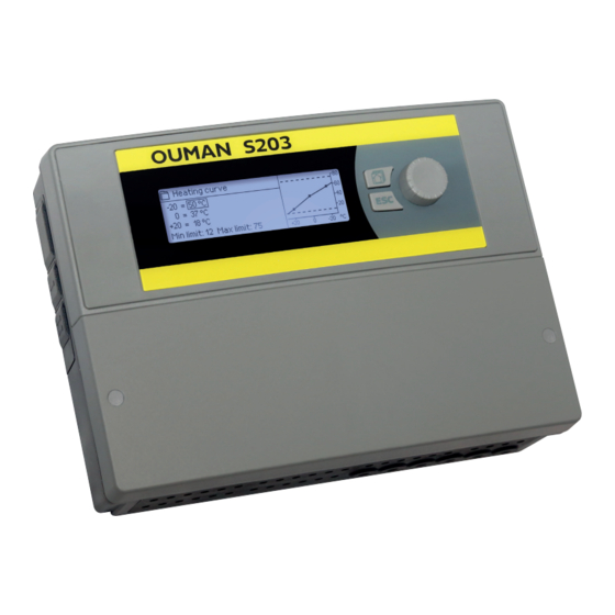
- Page 1 USER MANUAL S203 Controller for three circuits - control for 2 heating circuits - 1 domestic hot water control XM315G: Version 3.0-> Saving energy, creating comfort...
- Page 2 The user manual can also be downloaded from www.ouman.fi /en/document-bank/. The S203 is a heating controller for 3 circuits (two heating circuits and one hot water circuit). Wiring and configurating selections define what is seen on the display screen.
-
Page 3: Table Of Contents
Contents 1 Display menus 1.1 Basic view 1.2 Favourite views 1.3 Menu structure 2 Inputs and outputs 3 Regulation of supply water in heating circuits 3.1 Info 3.2 Heating curve 3.3 Setting values 3.4 Control mode 3.5 Time programs 3.5.1 Weekly schedule 3.5.2 Exception schedule 3.5.3 Special days 3.5.4 Temp. -
Page 4: Display Menus
1 Display menus Different levels of display menus are used to make the S203 clear and easy to use. The basic view shows the most important information for monitoring operation of the unit. Favourite views that can be changed by users enable them to easily access desired menus. Setting values needed by the user can easily be found in the versatile menu structure. -
Page 5: Favourite Views
1.2 Favourite views You can easily navigate from the basic view to the desired menu using the favourite view function. You can navigate from one favourite view to another by pressing the button. There can be a maximum of five of these views. -
Page 6: Menu Structure
1.3 Menu structure In the user manual Page 7 Main menu > Inputs and outputs IInputs and outputs > H1 Control circuit Home/Away mode Home > H2 Control circuit > ---------------------------------------------------- > DHW Domestic hot water control Outdoor temp. -18.2 °C Relay 1 control H1 Supply water 35.1 °C... -
Page 7: Inputs And Outputs
2 Inputs and outputs You can see the inputs and outputs of S203 which are configured Main menu in use. Configuration of the inputs and outputs is done in ser- Inputs and outputs > vice menu (see p. 36-39).General measurements are temperature H1 Control circuit >... - Page 8 Measurement Range Measurement information ----OUTPUTS----- Actuator control 0..100 % Current actuator 1 control Actuator control 2 0..100 % Current actuator 2 control. If series driving is in use, actuator 1 will first open the valve and the controller will then start up actuator 2. P2.1 (2.2, P3.1, P3.2) Off/On Pump control status.
-
Page 9: Regulation Of Supply Water In Heating Circuits
3 Regulation of supply water in heating circuits The S203 enables control of two different supply water circuits Main menu independently (H1 and H2). Inputs and outputs > H1 Control circuit > H2 Control circuit > Regulation of the temperature of supply water is controlled by DHW Control circuit >... - Page 10 Factors effecting the room temperature Explanation ----- ROOM TEMPERATURE -------------- Room temperature setting Room temperature setting set by the user. Time program effect on room temp. Room temperature drop by weekly or exception schedule. Away -control effect Home/Away mode for reduction of room temperature. The trigger can come from the controller (see Inputs and outputs->...
-
Page 11: Heating Curve
H1 (H2) Control circuit-> Heating curve The supply water temperature for different outdoor tempera- H1 Control circuit tures is set with heating curve. With S203 the heating Supply water information > curve can be adjusted exactly to meet the needs of the facility Measurements >... - Page 12 Suppl.w. 3 = 37°C/ Outd.t. 4 = 10°C/ Suppl.w. 4 = 28°C/ S203 will make the requested changes and send a new message H1 Heating curve Suppl.w. (+20) = 18 °C showing the changes made.
-
Page 13: Setting Values
3.3 Setting values The regulator has two types of setting values: those that are al- H1 Control circuit ways visible and those than can only be changed using a service Info > code (see page 35). Heating curve > Setting values >... -
Page 14: Control Mode
Manual Manual mech. control Control mode Explanation Automatic S203 controls the supply water temperature automatically according to the heating demand and time programs. Continuous normal temp. Forced normal heating. All time programs are by-passed. Continuous temp. drop Forced temperature drop. All time programs are by-passed.w Manual The controller runs the valve to manual position. -
Page 15: Time Programs
3.5 Time programs H1 (H2) Control circuit-> Time programs Weekly schedules, special days and exception schedules can be H1 Control circuit added to heating regulation in the S203. You can lower tempera- Heating curve > Setting values > tures desired times by using these time programs. -
Page 16: Exception Schedule
3.5.2 Exception schedule H1 (H2) Control circuit-> Time programs -> Exception schedule You can easily make changes that differ from normal routine Time use by using the exception schedule. The date, time and mode Add new > to which heating will be changed in the period in question are entered in the exception schedule. -
Page 17: Domestic Hot Water Control
4 Domestic hot water control The S203 keeps the temperature of domestic hot water at the Main menu designated value. Because of the danger of bacteria, it is recom- H1 Control circuit > mended that the domestic hot water temperature is not perma- H2 Control circuit >... - Page 18 You can use manual mode for example when a sensor Manual malfunctions. Manual mechanical Automatic S203 maintains the temperature of domestic hot water at the setting value set by the user. Manual The desired position of the valve is set with the setting value ”Actuator Manual position.”...
-
Page 19: Time Programs
4.1 Time programs DHW Control circuit-> Time programs You can change the supply water temperature with time program. DHW Control circuit You can define in Supply water settings how much the time pro- Info > gram deflects the temperature from the normal supply water set- Setting values >... - Page 20 Exception schedule DHW Domestic hot water control -> Time programs -> Exception schedule Time You can easily make changes that differ from normal routine use Add new > by using the exception schedule. The date, time and mode to which domestic hot water temperature will be changed in the pe- riod in question are entered in the exception schedule.
-
Page 21: Relay Control
The setting value is used in domestic hot water control, which is ”Domestic hot water setting value” - ”DHW reduction amount”. 5 Relay control In S203 there are 6 pcs of 24 VAC triac-controls, which can be changed to external controls via relay controls. Relay control 1... - Page 22 Relay 1 control Heating thermostat and time control: The relay is controlled ac- cording to the time program and the temperature. The relay is on when Function Heat therm.. & time ctrl (TR5) Setting value 5.0 °C > the temperature is below the setting value and the time program allows Time program >...
-
Page 23: Trends
6 Trends S203 saves automatically trend data from measurements. Trends Outdoor temp. > When you press OK on the measurement in Trend menu you can ---------------------------------------------------- H1 Supply water > review the trend log, change the sampling interval or save the H1 Return water temperature >... -
Page 24: Alarms
Deviation alarm PR 1 GROUP 1 Alarm signal can be muted by pressing Esc key. It shoud be noted S203.TE02.DA111 H1 Supply water temp. =10.2 °C that the alarms remain unacknowledged. You can find both active Received: 08.11.2020 02:27 alarms and Alarm history in the Alarm menu. - Page 25 Active alarms In the alarm menu of S203 device, you can check the active alarms Alarms and what alarms have been active. The number of active alarms Active alarms > will be shown in the right corner of the main view.
- Page 26 Routing schedule Alarms > Routing schedule S203 default alarm groups are: • Group 1: Urgent alarm that should always be immediately Routing schedule routed. Group 1 Weekly schedule > Group 1 Alarm routing now Team 1 > • Group 2: Malfunction alarms than can be frouted during busi- Group 2 Weekly schedule >...
-
Page 27: System Settings
Enter hours 19:44 The S203 clock takes daylight savings and leap years into account automatically. The clock has a backup for power outages lasting hh:mm about two days. -
Page 28: Text Message (Sms) Settings
(the number does not appear on the display). Test for communication. SMS PIN: If the SIM card has PIN inquiry in use, S203 device asks you to enter the PIN. Entering the code: •... -
Page 29: Network Settings
8.3 Network settings If you want to connect the S203 unit to an Ethernet network, you S203 will need M-LINK device (additional equipment). M-LINK is con- nected to RJ-45 port 1 located in the side of the controller. The maximum length of the RJ-45 cable is 10m and all 4 pairs must be connected. - Page 30 503 > Modbus RTU settings: If S203 is connected to the Modbus RTU bus as a slave, you have to set the address of the S203 device. Note! All the slave devices connected to the bus must have unique address.
- Page 31 - - - - - - - - - - - - - - - - - - - - - - - - - - - - - - - - - - - - - - tivate the ACCESS-service in order to be able to use it. OUMAN ACCESS- service is “off” by default in S203. The S203 de- vice will be connected to a C port of M-LINK device or as a slave device to the Modbus RTU bus.
-
Page 32: Display Settings
The factory setting of lock code is 0000. Approve: Press OK for a number of seconds 1. S203 device asks you to enter the current code. The factory set- Cancel: Press ESC for a number of seconds ting of lock code is 0000. -
Page 33: Connection Guide
OUMAN RJ45 Port I. If M-Link device is connected to current supply GSMMOD S203 RJ45 port 1, the modem should be con- nected to M-LINK device’s contact C. RJ45-1 Operating voltage for the GSM modem can be taken from the external power supply. - Page 34 Alternative connections M4, M7, M12, M13 and M14 M 4: H1 Room temperature measurement M 4: Temperature measurement (H1 Heat exchanger DH Return water sensor) TMR or 2x0,8 2x0,8 TMW/TMS 0-10V transm. M 7: H2 Room temperature measurement M 7: Temperature measurement (H2 Heat exchanger DH Return water sensor) TMR or 2x0,8...
- Page 35 Analog outputs Triac controls Actuators control of H1 Heating circuit H1 Voltage controlled actuator Y1 output 3-point controlled actuator 0-10V DC-ctri 3x0,8 Open 3x0,8 24 VAC 51 or 52 24VAC Connect 24 VAC to strip connector 55, if it is selected that Manual mechanical control is Closed “available”...
- Page 36 The bus cable’s shield (FE) is connected to the BG 120 Ω device connector of the S203. In the master device the shield can be left disconnected or be connected to a potential free contact. A 120 Ω terminating Master- Data resistor is connected to both ends of the bus.
-
Page 37: Connections And Configuration
9.1 Connections and configuration The user interface is grouped according to the control circuits Connections and configuration and the functions. UI 1: Outdoor temp. In use > UI 2: H1 Supply water In use > When you press OK on the input/output, opens a menu, where UI 3: H1 Return water Not in use >... - Page 38 Alternative measurement Inputs Attention options Name: Meas. M12; other specify ____________________________________ Meas. 12 Temperature measurement -> Pressure transmitter: Pressure switch Pressure switch: Measuring area _____(16.0 bar) Digital input type: Pressure transmitter V Measurement adjustment ______ (0.0) Pressure transmitter mA normally open Name: (Pressure measurement 1) , other normally closed specify _______________________________...
- Page 39 ACTUATOR CONTROLS Name Output Actuator selection Running time / factory setting (setting range) Running time open ____ 150 s (10...500 s) H1 Actuator control 0-10 V / 2-10 V / Running time close ____ 150 s (10...500 s) 10-0 V / 10-2 V Manual mech.
- Page 40 RELAY CONTROL Meas. controlling the relay/Name of Output Control mode Setting values (default) control TR 5 Relay control 1 Heating/ Heating thermostat Outdoor temperature Cooling thermostat: Measurement 10 Cooling thermostat Setting value _____(21.0°C) Hysteresis _____(1.0 °C) Name of control (TR5 control) Defrost thermostat other, specify Defrost thermostat:...
-
Page 41: Service Settings
10 Service settings Service mode includes all settings of the controller. Some of the settings can be found also from “setting” menus of the heating circuits (H1, H2, DHW). CONTROL CIRCUIT SETTINGS Setting Factory setting Range Explanation Control circuit In use In use/ Control circuits are already taken into use in start-up wizard. - Page 42 Summer function Pump summer stop In use In use/ If S203 controls also the pump, the pump can be stopped while the sum- Not in use mer function mode is active. Summer function outd. 19.0 10 ...
- Page 43 Explanation setting Not in In use/ Outdoor temp. forecast S203 uses temperature forecasts from bus for continousing. Not in use Valve summer shut-down In use In use/ The setting is used to select whether or not the regulation valve is closed Not in use when the summer function is in use.
- Page 44 Factory Setting Range Explanation setting Return water compensation Return water compensation 0 ... 7.0 If the return water temperature decreases below the low limit (freeze risk), the supply water temperature will be increased. The amount of ratio increase is the amount of undershoot (low limit - return water tempera- ture) multiplied by the compensation ratio.
- Page 45 Alarms Enable DIsable/ It’s possible to disable all alarms of S203. This can be done e.g. in the Enable cases when the measurements are configured before any sensors are linked to controller. When alarms are disabled, a symbol is shown in the start menu.
- Page 46 Factory Setting Range Explanation setting Tuning values H1 and H2 Tuning values: P-area 2...600 °C Supply water temperature change at which the actuator runs the valve at 100%. E. g. If the supply water temperature changes 10 °C and the P area is 200 °C the position of the actuator changes 5 % (10/200 x 100 % = 5 %).
-
Page 47: Restore Settings And Updates
Insert microSD memory card which includes new software to con- troller S203 asks: ”Would you like to restart device?” Select: ”Yes” S203 reboot to start the update of the new software. The updating of the software takes few minutes. Update external display firmware S203 Insert the memory card containing the new firmware for the external display in the controller. -
Page 48: Turn The Display Unit
12 Turn the display unit If you want to bring the cables to the regulator from above, you must turn the display unit ac- cording to the following instructions. When you turn the display, the controller will be no electricity. Open the front cover screws and remove the front cover. -
Page 49: Optional Accessories
Insert SIM card into the slot and make sure it settles properly. Push the slot back to its place. Set the SIM card PIN code as S203 device PIN code. Make sure PIN inquiry is in use in the SIM card. -
Page 50: Text Message Quick Reference
Text message quick reference If a GSM modem is connected to the S203 you can communicate with the controller by text messages using command words. Send the following text message to the controller: KEY WORDS. If the controller has a device ID in use, always write the device ID in front of the key word (example. -
Page 51: Index
Index 5-point curve 11-12 External display 32, 47, 49 Restore factory settings 47 External power source connection 36 Return water compensation 37, 44 Access 29, 31 Return water freezing risk alarm 45 Active alarms 4, 25 Favorite views 5 Return water temperature 7, 37 Actuator running time 39, 46 Floor heating anticipation 42, 43 Room compensation 43... -
Page 52: Tecnical Information
S203 Tecnical information Dimensions width 230 mm, height 160 mm, depth 60 mm Weight 1.3 kg Protection class IP 41 Operating temperature 0 ºC…+50 ºC Storing temperature -20 ºC…+70 ºC Power supply L(91), N (92) Operating voltage /Power require- 230 Vac / 200 mA. The controller always requires 230 Vac / 200 mA. In addition,...
Need help?
Do you have a question about the S203 and is the answer not in the manual?
Questions and answers