Table of Contents
Advertisement
Quick Links
Freely programmable automation device
- Ouflex is a DIN-rail-attachable, monitoring-, controlling- and regulating device.
- The DIN-standard-compatible structure of the Ouflex device enables installation
to most common cabinets.
- Detachable strip connectors make installation easier.
KEY WORDS
Key words:
Active alarms
Alarm history
Use of a GSM phone requires that
the GSM modem (optional) is con-
nected to the controller.
OUFLEX
USER MANUAL
OUNET
Internet-based on-line control room
for professional remote
control and monitoring (optional).
EH-net
Local Web Server
remote control and monitoring (op-
tional).
Advertisement
Table of Contents

Related Manuals for OUMAN Outflex


Summary of Contents for OUMAN Outflex
- Page 1 OUFLEX Freely programmable automation device USER MANUAL - Ouflex is a DIN-rail-attachable, monitoring-, controlling- and regulating device. - The DIN-standard-compatible structure of the Ouflex device enables installation to most common cabinets. - Detachable strip connectors make installation easier. KEY WORDS Key words: Active alarms Alarm history...
- Page 2 Ouflex is a DIN-rail-attachable and freely programmable device designed for monitoring, controlling and re- gulating. The device is programmed with OuflexTool utility and the prepared program is loaded to the Ouflex device via Ethernet connection. It is possible to increase the number of I/O-points with external I/O-modules via Modbus RTU connections.
-
Page 3: Table Of Contents
Contents 1 System settings ..............................4 1.1 Setting date, time and language ..........................4 1.2 Text message (SMS) settings ........................4 1.3 Network settings ..............................5 1.3.1 IP settings ................................. 6 1.4 Display settings ..............................9 1.5 Type info ................................9 1.7 Backup ................................ -
Page 4: System Settings
1 System settings M a i n m e n u System settings include setting the time, date and language, as well System settings > as text message (SMS) settings, network settings, display settings and Alarms > Point info > device type information. -
Page 5: Network Settings
A network connection mode it is shown whether Ouflex device is in the network or not. Ouflex device can be connected to a local network or the Internet. If you use a protected VPN connection via OUMAN Access service, the controller displays the network mode OUMAN Access. -
Page 6: Ip Settings
1.3.1 IP settings System settings > Network settings > IP settings IP settings IP settings DHCP Off > Setting the IP address via DHCP function: Gateway adress 0.0.0.0 > Subnet mask 0.0.0.0 > IP address 0.0.0.0 > Go to DHCP and press OK. Nameserver address 0.0.0.0 >... - Page 7 Internet are open. OUMAN ACCESS- service is “off” by default in Ouflex. OUMAN ACCESS- service is taken in use in following way: Ouman support feeds in the target and billing information to the Ouman system and activates the service based on the serial number of the Ouflex device. After that, you have to activate the ACCESS service from the device.
- Page 8 System settings > Network settings -> Modbus TCP/IP Modbus TCP/IP settings Modbus TCP slave (server) settings are changed via Modbus TCP/IP Modbus TCP/IP settings. It is possible to communicate with an Ouflex device and the Modbus TCP port (internal registers) 5 0 2 >...
-
Page 9: Display Settings
Serial number xxxxxxx by the user of Tool. This information is useful especially in case of Application version 0.0.0 Ouman Ouflex 0.0.0 maintenance or upgrade. Display 1 .1 .1 75 >... -
Page 10: Alarms
2 Alarms Ouflex can send an alarm for a number of different reasons. Infor- A l a r m s mation about the alarm is shown on the display. The alarm also Active alarms > sounds a beeping noise. Alarm history >... -
Page 11: Routing Schedule
2.4 Routing schedule Alarms > Routing schedule (SMS use only) R o u t i n g s c h e d u l e You can see where alarms are currently being routed in the routing Group 1 Weekly schedule >... -
Page 12: Alarm Parameters
2.5 Alarm parameters Alarms > Alarm parameters All the alarms can be found there. Each application has its own Alarm parameters ”alarm parameter”-folder. A person who knows the service code Burglar monitoring > can change the alarm parameters. Fire monitoring >... -
Page 13: Point Information
3 Point information Point info In the point info you can see wiring info, bus points and time pro- Wiring info > Bus points grams. > Time programs > 3.1 Wiring info Point info -> Wiring info Wiring info Point information shows all the inputs and outputs of the Ouflex INPUTS: device and where the inputs and outputs have been connected. -
Page 14: Weekly Schedule
3.3.2 Weekly schedule Time programs -> Weekly schedule Graph Weekly programs have a general graphic view and an editing view, Weekly/24-hour program where you can see when the control is activated. (e.g., temperature Monday > drop, car heating on, lights on). Tuesday >... -
Page 15: Special Days
3.3.3 Special days Time program > Special days You can enter special day programs as exceptions to normal week- ly programs. You can designate a maximum of 7 special day po- Graph Relay 3 Special days grams (SD). A special day program is typically created for each SD 1 >... -
Page 16: Settings
4 Settings In Ouflex, settings can be classified into the following categories: Asetusarvot Settings • Main settings Huonelämpötila Room temperature 21.0 °C > 21.0 °C > • Hidden settings Lämmönpudotus ( huonelämpö ) Temperature drop (room temperature ) 1.5 °C > 1.5 °C >... -
Page 17: Naming
6 Naming There may be fields that you can rename in your Ouflex device. You Room selection often download an application where general names have been gi- Name of room 1 Room 1 > Name of room 2 Room 2 > ven to the controls, and you may want to rename them more accu- rately. -
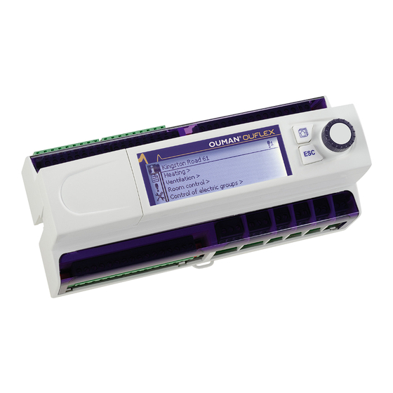
Page 18: Ouflex Device I/O Connections And Structure
7 Ouflex device I/O connections and structure Ouflex is a freely programmable and DIN-rail-attachable building automation system for cont- rol and monitoring. The DIN-standard-compatible structure of the Ouflex device enables instal- lation to most common cabinets. Detachable strip connectors make installation easier. Detachable connector shield Home button Control knob and OK button... - Page 19 Ouflex includes 34 I/O-points, and also versatile data transfer and field bus connections. In additi- on, the device contains 24 Vac and 15 Vdc outputs. Display unit is detachable, and can be relocated. It is possible to increase the number of I/O-points with external I/O-modules via bus connections. 10 11 12 13 14 15 16 21 22 71 72 73 74 75 76...
-
Page 20: Communication Via A Mobile Phone
8 Communication via a mobile phone If a GSM modem is connected to the Ouflex you can communicate with the KEY WORDS regulator by text message using key words. Send the following text message to the controller: KEY WORDS. Key words: You can send the text message question mark to the controller to get a list of Active alarms Alarm history... - Page 21 Ouman GSM modem (GSMMOD6) can be connected to the straight to controller. The modem has a fixed antenna that can be changed to an external antenna with a 2,5m cord (optional equipment) if needed. The modem’s indicator light shows what mode it is in.
- Page 22 Product disposal: The enclosed marking on the ad- ditional material of the product indicates that this product must not be disposed of together with household waste at the end of its life span. The product must be processed separately from other waste to prevent damage caused by un- controlled waste disposal to the environment and the health of fellow human beings.
-
Page 23: Extension Units
Extension units Flex Combi 32 is a DIN-rail-attachable and RS-485-connected univer- sal I/O extension unit. It has comprehensive I/O space, and 24Vac and 15Vdc outputs. The device has: 16 pcs. universal measurement inputs (UI) that can read: - Passive sensors - Transmitters - Digital inputs - Pulse information 4 pcs. -
Page 24: Technical Information
OUFLEX Freely programmable automation system Technical information Protection class IP20 Operating temperature 0 ºC…+40 ºC Storing temperature -20 ºC…+70 ºC Power supply Operating voltage 24 Vac, 50 Hz (22 Vac - 33 Vac) Power required (15 Vdc output = 0 A) 13 VA (15 Vdc output = 750 mA) 34 VA Notice! Please consider 24 Vac operating voltage and power required for Triac outputs.
Need help?
Do you have a question about the Outflex and is the answer not in the manual?
Questions and answers