OUMAN EH-800 Series User Manual
Hide thumbs
Also See for EH-800 Series:
- Installation instructions manual (12 pages) ,
- Quick manual (2 pages)
Table of Contents
Advertisement
Quick Links
Advertisement
Table of Contents

Related Manuals for OUMAN EH-800 Series


Summary of Contents for OUMAN EH-800 Series
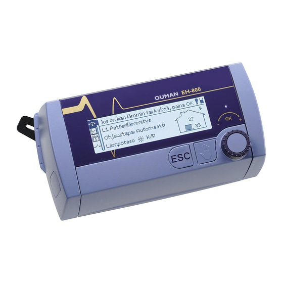
- Page 1 OUMAN EH-800 Heating controller USER MANUAL...
- Page 2 EH-800 is a heating controller for private homes and business facilities having heating systems with circulating wa- ter. An extension unit can be obtained as optional equipment making it possible to take a second control circuit into use. If a second control circuit has been taken into use, numbers 1 or 2 will appear on the main display indicat- ing which control circuit is in use.
-
Page 3: Table Of Contents
Table of contents Fine adjustment ..............T aking the H2 control circuit into use ........H2 Process settings ............... Heating curve settings ............. Selection of heating mode ..........Actuator selection ............. Säätöpiirikohtainen perusvalikko ........Actuator driving time............Measurements ................Selection of type of heating curve ......... Graphic presentation of meas. -
Page 4: Fine Adjustment
Fine adjustment The fine adjustment function enables you to make small changes Instructions: in temperature. It pays to use this function when the room tempe- rature remains the same but it is too cold or too hot. Press OK in the main display. Room temperature measurement in use: Turn the control knob in the desired direction and press OK to confirm. -
Page 5: Heating Curve Settings
The supply water temperature for different outdoor temperatu- The heating curve needs to be adjusted if the room tempera- res is set in heating curve settings. With Ouman EH-800 the heating ture does not remain even when the temperature is below ze- curve can be adjusted exactly to meet the needs of the facility from ro and falling. -
Page 6: Säätöpiirikohtainen Perusvalikko
Basic menu: Measurements Basic menu -> Measurements The measurements menu displays present information about connected sensors and valve posi- tions. A factory set supply water sensor is connected to the controller. It has a separate plug-in for > Measurements outdoor temperature. Information about measurement channels 3 and 4 on pages 23-25. Measu- H1 Supply water temperature 35.1 °C rements 5 and 6 are also in use if an extension unit has been connected to the controller. -
Page 7: Graphic Presentation Of Meas. History Information
Use the trend display to easily monitor, e.g., temperature drops and You may use Ouman Trend software to look at a trend file as a chart. Go to www.ouman.fi to download the software. -
Page 8: Supply Water Info
Basic menu: Supply water info Basic menu -> H1 (H2) Supply water info The supply water info shows which factors are effecting the supply water temperature at the time of inspection. The starting point is the supply water temperature according to the >H1 Radiator heating...H1 Supply water info outdoor temperature (according to the heating curve). - Page 9 Supply water info Factors effecting the supply water temp. Explanation Supply water temperature drop due to the maximum limit. Effect of maximum limit Supply water temperature increase due to the minimum limit. Effect of minimum limit Both the general minimum limit set for the supply water and -20°C outdoor temperature effect the mi- nimum limit.
-
Page 10: Room Temperature Info
Basic menu: Room temperature info Basic menu -> H1 (H2) Room temperature info If a room sensor is connected to the controller, you can check the room temperature info to > H1 Radiator heating > Basic menu see which factors determine the room temperature at the time of inspection. Measurements >... - Page 11 Basic menu: Settings Basic menu -> H1 (H2) Settings The EH-800 controller’s settings are divided into two groups; main settings and less frequent- > H1 Radiator heating > Settings ly adjusted special settings which can be seen by pressing OK for a number of seconds. The- Room temperature 21.0 °C >...
-
Page 12: Settings
Settings Note! Some of the settings (special settings) are hidden. Press OK for a number of seconds to alternately make them appear or disappear. Factory- Range Information about settings Setting setting Supply water minimum limit 5.0...95.0°C Minimum allowed supply water temperature. A higher minimum temperature is used in damp radiator heating 12.0°C rooms and tiled rooms than in, e.g., rooms having a parquet floor to ensure a comfortable tem-... -
Page 13: Control Modes
Basic menu: Control modes Basic menu -> H1 (H2) Control modes The selected control mode always appears in the controller’s basic display. Radiator heating > Basic menu Supply water info > Changing the control mode: Turn the control knob to move to control mode in the basic display. -
Page 14: Other Controls
The Home/Away control is only in effect if the controller is on automatic control. Home When you send a Home or Away message, the controller sends back an OUMAN mes- Away sage showing that the HOME or AWAY control is on. -
Page 15: Relay Control
Other controls: Relay control Other controls -> Relay control Relay control is in use if an extension unit is connected to the controller. Relay control is ta- >Other controls ken into use from the controller’s device settings. Relay control can be used to stop the pump Home/Away control No H/A control >... - Page 16 Relay control Other controls -> Relay control Relay use Explanation Relay control according to the temperature difference: > Other controls > Relay control Relay control Accord. to the temp. difference Two different temperatures are compared, e.g., the temperatures of the solar collector and ac- Control mode Automatic> cumulator. When the temperature difference is large enough, e.g., 10 °C, the solar collector’s Temp. of solar collector (A) 68.3°C >...
- Page 17 Relay use Explanation Relay control according to the time program: The relay changes its mode according to its week/24 hour program. The controller’s display > Other controls > Relay control shows the present control mode. The relay’s week/24 hour program can also be found under Relay control Accord. to the time program clock programs.
-
Page 18: Clock Functions
Temperature drop Weekly/24-hour program Clock functions -> H1 (H2) Weekly/24-hour program Adding a new switch time: Clock functions Press OK at the “Add new” row. 09:02 Press OK. Set the switch time (set hours and minutes separately) Fr 05.02.2009 and press OK. Press OK and then turn the control knob to set the temperature le- vel and press OK. -
Page 19: Exception Calendar
When you send a Home or Away message, the cont- e.g., when going on a vacation for a longer period of time. If the roller sends back an OUMAN message showing that the HOME or controller’s pre-increase function has been taken into use, set the AWAY control is on. -
Page 20: Setting The Time And Date
Time and date Alarm notice Clock functions -> Time and date Danger of freezing alarm It is important that the time and date are correct, because, e.g., Supply water temperature 10.2 °C Received: 08.11.2008 klo 02:27 in alarms you can see when the alarm has become activated and when it has become inactive. Press control knob to acknowledged the alarm. -
Page 21: Alarms
Alarms Alarms You can set alarm limits from the controller’s alarm menu. Turn the control knob so the num- Alarms ber is outside of the setting range to take the alarm out of use. The text “Not in use“ will Alarm limits appear on the display. -
Page 22: Device Settings
Alarms Emptying the alarm history: Active alarms: The controller asks for confirmation before it empties the alarm his- Alarms tory. Alarm limits Active alarms > Notice Inactive alarms > Empty alarm log > Empty alarm history Active alarms Yes 17.10.2009 13:29 Outdoor temperaturmpötila > 19.01.2009 14:12 Supply water temperatur > Relaying alarm information to a mobile phone: If a modem has been connected to the controller and Each active alarm is displayed on a separate row with its activati- a phone number has been given to which the alarm... -
Page 23: Settings For Measurement Channels
Device settings: Measurement channel settings Device settings-> Measurement channel settings 3. Select the measurement channel use. (additional information about uses on the next page). Press OK. Device settings 4. Measurement channel 3 is now being used for room temperatu- Language/Kieli/Språk... English > Measur. channel settings >... - Page 24 Measurement Measurement channel Measurement information Outdoor temperature If the controller is taken into use as a constant temperature controller, the outdoor temperatu- re measurement is activated here and also inactivated if necessary. H1 Supply temerpature H1 control circuit’s supply water sensor connected to the controller. 3 and 4 Room temperature TMR The controller uses the TMR room sensor to measure the room temperature.
- Page 25 Connection of measurements 5 and 6 using the extension unit You may examine trend via browser using Ouman Trend RJ45-2 plug connection Extension unit software. Go to www.ou- EXU-800 man.fi to download the soft-...
-
Page 26: H1 Process Settings
Device settings: H1 Process settings/ Heating mode Device settings -> H1 Process settings -> Heating mode Radiator heating, normal: this heating mode is a factory setting. Device settings...H1 Process settings Heating mode Radiator heating, normal > H1 Heating curve The curve is Direction of valve Open clockwise> -20 = 58 °C equivalent to the Heating curve type 3-point heating curve >... - Page 27 Heating mode Device settings -> H1 Process settings -> Heating mode Special application for the constant temperature controller: Constant temperature controller: When the controller is being used as a constant temperature cont- The controller keeps the supply water temperature constant re- roller, the set temperature for the supply water can be compensated gardless of the outdoor temperature (special use).
-
Page 28: Direction Of Valve
Valve direction The range of movement of boiler valves is mechanically limited to 90°. There- fore, it is easy to find the limits by turning the valve to the extreme limits using the manual control knob or axle. Sometimes it may be difficult to determine the Device settings->... -
Page 29: Selection Of Type Of Heating Curve
Selecting the type of curve Device settings -> H1 Process settings -> Heating curve type A 5 point curve offers even more possibilities to make a curve of Heating curve type just the right shape to exactly meet the heating need of your facili- 3-point heating curve ty. -
Page 30: Labeling Heating Circuits
Control circuit name Device settings-> Process settings -> Name of control circuit Labelling: The EH-controller automatically names the control circuit according to the selected heating mode (radiator heat, floor heat, damp rooms, Turn the control knob and press OK to confirm. constant heating controller). -
Page 31: Cascade Control
Boiler 2. source of heat accumulator E.g. oil-fired boiler 24 VDC 0 - 10 V max. 24 VDC/3W actuator e.g.. Belimo HTC24-SR Cascade control actuator connection A diagram illustrating cascade control. For more diagrams, see www.ouman.fi. to EXU-800 extension unit. -
Page 32: Hybrid Heating
24 VDC/3W actuator temperature measurement, Meas. 4: Meas. 3 Connecting charge pump e.g. TME Accum. actuator and solar collector tem- A diagram illustrating hybrid heating control. temp. perature sensor to EXU-800 ex- See www.ouman.fi for more diagrams. tension unit. - Page 33 Hybrid heating Device settings -> Hybrid heating Factory Setting Information about the setting: Setting: setting range Hybrid heating Not in use If hybrid heating is taken into use, the controller automatically reserves measurement chan- Not in use In use nels 4 and 5 to hybrid heating temperature measurements (meas. 4 for accumulator tempe- rature, meas.
-
Page 34: Taking The H2 Control Circuit Into Use
Initiation of the second control circuit and relay controls on pa- .Actuator selection EXU-800 ge 32-35. These functions can be taken into use if the controller 0-10 V is connected to the extension unit, OUMAN EXU-800 (optional 8 (24 VDC OUT) 9 (Y) 2-10V equipment). -
Page 35: Relay Control
Relay control Relay control according to the temperature: Device settings -> Relay control Relay control can be taken into use if an extension unit has been con- > Laiteasetukset... Pumpun kesäpysäytys Device settings > Relay control nected to the controller using an RJ45-2 channel. Select the relay use. Relay control According to the temperature >... - Page 36 Relay control according to the temperature difference: Relay control according to the valve position:: > Laiteasetukset... Pumpun kesäpysäytys > Laiteasetukset... Pumpun kesäpysäytys Device settings > Relay control Device settings > Relay control R e l a y c o n t r o l A c c o r d . t o t e m p . d i f f e r e n c e Relay control Accord. to H1 valve position Meas. A that controls relay Solar collector >...
-
Page 37: Valve Flushing
Valve flushing Device settings -> Valve flushing It pays to take the valve flushing function into use when there are im- V1 valve position during flushing purities in the fluid circulating in the pipes or if the position of the val- Not in use ve is not changed in a long time (e.g., the summer function is taken into use). -
Page 38: Text Message Settings
Approve: Press OK a few seconds Cancel: Press ESC a little file RJ45-2 Me s sage c entre number s: B. Using the extension unit +35844 798 3500 Saunalahti +35845 110 0100 OUMAN TeliaSonera +35840 520 2000 Tele Finland +35840 520 2330 GSMMOD5 Extension unit Modem Elisa +35850 877 1010... - Page 39 Alarm numbers 1 and 2: The controller sends alarm information to two GSM numbers designated here. Text message limiting (24 h): You can limit the number of text mes- sages that the controller sends in a 24 hour period here. The cont- Alarm number 1 roller also has a limiting function that allows only 5 messages to be sent about the same alarm in a 24 hour period.
-
Page 40: Eh-800 Network Settings
4. Write down the following information: ded intranet and can be controlled using a computer’s browser. - IP-address, for example, 10.2.74.146 When connecting the device to the internet, Ouman recommends - Subnet mask, for example, 255.255.255.0 using Ouman internet and information security solution 3G STD - Gateway, for example, 10.2.74.1... - Page 41 OUMAN ® Ouman products 3G PRO and 3G STD make it easy to establish an internet connection. The EH-800 controller can be found with the na- me you have given it ( e.g., http://avenue1.ouman.net). Necessary information and settings that are needed daily appear on EH-800’s basic display.
-
Page 42: Display Settings
Display settings Taking the locking code into use Device settings -> Display settings Device settings -> Locking code Device settings> Display settings Device settings Adjusting the contrast 75 > Valve flushing Turning the display Normal > Telecommunication settings > Display settings Locking code Not in use > Adjusting the contrast: You can adjust the contrast. At 0 the display is If you take the locking code into use, you can read controller infor- bright and at 255 it is black. -
Page 43: Changing The Locking Code
0 0 0 re are several locations to control. Approve: Press OK a few seconds Cancel: Press ESC s little while Device settings > Type information Type: OUMAN EH-800 > Write the new code on top of the old locking code. Program version: V2.2.2.B4 > Serial number: 05146838 > Select a new locking code Location >... -
Page 44: Communication Via A Mobile Phone
Type information controller to a temperature drop or nominal temperature. Send the following text message to the controller: KEY WORDS. The Ouman key word gives you temperature Text message measurement information (outdoor temp., supp- You can send the text message question mark to the controller to... - Page 45 (auto, ON or OFF). From: EH-800 Home formative OUMAN message as a return messa- Exception calendar: You can change the present exception calen- ge. The message shows the temperature to which OUMAN: Outdoor temperature = -1.2/...
-
Page 46: Special Settings
Special settings Basic menu -> H1 (H2)Settings -> Press OK for a number of seconds Other settings for room control > Here are more seldom needed settings which are hidden during normal use. Press OK for a number of seconds for them to appear and disappear in turn. The symbol appears in front of special settings. - Page 47 Setting Factory Setting Information about settings setting range Other settings for room control > Room temp. range, 5.0°C 0.0...95.0°C Limiting the lower limit for the room temperature range. Limiting the range can prevent an minimum value incorrect setting from being set. Room temp.
- Page 48 Special settings Basic menu -> H1 (H2) Settings -> Press OK for a number of seconds Setting Factory Setting Information about settings: setting: range: Supply water range, 0.0°C 0.0...95.0°C When the controller has been taken into use as a constant temperature controller, the supp- min value ly water constant temperature range can be limited by giving the range a minimum limit.
- Page 49 Setting Factory Setting Information about settings: setting: range: Stand-by settings: Supply water free 10 °C 0...50 °C In the stand-by function, the lower limit of the supply In the stand-by function the Supply water lower limit of the supply wa- °C temp.
- Page 50 Special settings Basic menu -> H1 (H2) Settings -> Press OK for a number of seconds Setting Factory Setting Information about settings: setting: range: Autumn drying function and settings: Autumn drying Room temperatur 1.0°C 0...5°C The amount the room temperature is raised when autumn drying is in use. (room sensor re- Supply water quired).
-
Page 51: Optional Equipment
Home/Away switch ANT1, External antenna surface or flush mounting An external antenna for the Ouman GSM/GPRS modem • Antenna with a small magnet base • Surface mounting, electr. no. 71 655 48 • 2,5 m antenna cable, FME connection • Flush mounting, electr. -
Page 52: Installation Guide
EH-800 installation instructions You can easily install the EH-800 controller yourself by following the instructions below. 1. Use the manual control knob to turn the valve all the way to the left, so the valve is either completely open or closed. If the valve is completely open, the valve direction in the controller’s menu must be changed to open in the counterclockwise direction. -
Page 53: Connections
EH-800 connections Detach the protective cover of the controller’s connection space (slides off at a right angle to the controller) and connect the outdoor sensor to the controller. H1 Supply water sensor Is attached to the controller 24 V Power source AC/DC H2 Supply water sensor Connected to the controller’s RJ45-2... -
Page 54: Initial Setup
EH-800 initial setup The settings of measuring channels (measurements 3 and 4): You can change the language of the controller, set the If you do not take additional connections into use, go to section 4. time and date and select the controller use during the ini- tial setup. - Page 55 Heating mode selection: Taking the second control circuit into use The controller has factory set curves and settings suitable for diffe- Connect the extension unit to the controller using the RJ45-2 and ta- rent heating modes that usually do not have to be changed. ke the H2 control circuit into use through the controller’s device set- Heating mode tings (see p.
-
Page 56: What To Do If There Is A Fault
(90°). At the same time, check that the valve direction is correct. If ler lever. Send the device to Ouman Oy. Include your name, address, te- the valve is stiff, ask an HVAC installer to clean the valve axle and hole lephone number and a description of the fault. -
Page 59: Index
Alarm that can be freely labelled 21, 23 Message centre number 38 Summer function 12, 15, 35, 49 Automatic control 13 Ouman key word 44 Summer stop 12, 15, 35, 49 Autumn drying 50 Outdoor temperature 2, 6 Supply water info 8-9 Big temperature drop 11, 13, 18-19 Outdoor temperature ’s 24-hour average 6... -
Page 60: Technical Information
3 ye Approvals: 89/336/EEC, 92/31/EEC EMC-directive Manufacturer: Ouman Oy -Interference tolerance EN 61000-6-1 Kempele Finland -Interference emissions EN 61000-6-3 Tel. +358 424 8401 Small voltage directive 73/23/EEC Fax +358 8 815 5060 -Safety EN 60730-1 www.ouman.fi OUMAN EH-800 v. 2.1.0_09112011...
Need help?
Do you have a question about the EH-800 Series and is the answer not in the manual?
Questions and answers