Table of Contents
Advertisement
Quick Links
Advertisement
Table of Contents

Related Manuals for TownSteel e-Elite 3000


Summary of Contents for TownSteel e-Elite 3000
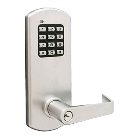
- Page 1 TownSteel e-Elite 3000 Installation Guide...
-
Page 2: Table Of Contents
Table of Contents Package Content Getting Started Door Preparation Step 1 - Latch Bolt & Strike Step 2 - Installing Outside Assembly Step 3 - Installing Backplate Step 4 - Connecting Wires Step 5 - Installing Inside Assembly Step 6 - Installing Covers Step 7 - Installing Inside Lever Addendum Exploded View... -
Page 3: Package Content
Package Content Parts in the box Backplate Inside Assembly Inside Lower Cover Outside Assembly Inside Upper Cover Collar Bearing Ring Inside Lever Latch Bolt & Screws Strike & Screws Backplate Screws Additional Parts Included Inside Assembly Screws Inside Cover Screw... -
Page 4: Getting Started
Getting Started Tools needed for lock installation Phillips Screw Driver (Not included) Lever Removal Tool Torx Wrench Note: Do not use a power drill for installation of lock - it can damage the lock. Handing Information... -
Page 5: Door Preparation
Door Preparation Prepare door and jamb per template provided. The backset is the dimension from the edge of the door to the centerline of the lock. Important: Door stop is where the door will stop when normally operated. The stop includes any gasket, smoke seal, or bumpers. -
Page 6: Step 1 - Latch Bolt & Strike
Step 1 Install the latch bolt and secure with 2 screws. Install strike and secure with 2 screws. Note: A right hand (RH) lock will be depicted in the following guide - for left hand (LH) install opposite. During installation keep the door open. Do not use power tools for assembly or you can potentially damage the door. -
Page 7: Step 2 - Installing Outside Assembly
Step 2 Install the outside lock assembly in the cutout. Guide the wire harnesses through the cutout. Line up the retractor on the lock body with the latch tail piece. Tighten the latch screws. Note: Do not pull or pinch the wire harnesses. Bearing ring should sit flush on outside lock... -
Page 8: Step 3 - Installing Backplate
YW1930... -
Page 9: Step 4 - Connecting Wires
Step 4 Plug in the wire harnesses where indicated on the inside assembly. Inside Motor Remote access assembly plug plug Motor Keypad conn plug Keypad conn... -
Page 10: Step 5 - Installing Inside Assembly
Step 5 Install inside assembly with 4 screws. Do not pinch wires. Install the 4 AA alkaline batteries provided. The keypad will light up green and the motor will run. -
Page 11: Step 6 - Installing Covers
Step 6 Install inside lower cover first. Tighten the bearing ring to hold cover in place. Install the inside upper cover - slide down from top - secure with screw using the wrench provided. Inside upper cover Torx wrench Inside lower Lever removal cover tool... -
Page 12: Step 7 - Installing Inside Lever
Step 7 Install the inside lever - ensure the lever is seated and is locked in place. Lever catch is on the side of lever and it should snap into place. Note: Check lock for correct operation before closing the door. See programming guide for help. -
Page 13: Addendum
Addendum 2. Insert lever removal tool into the lever catch hole and push back the lever catch. Lever catch hole 3. Remove lever. -
Page 14: Exploded View
Exploded View 1 x Inside Cover Screw Inside Upper Cover Inside Backplate Lever Bearing Ring Inside Lower Cover 4 x Inside Assembly Screws Inside Assembly Outside Collar Assembly Latch Bolt 2 x Backplate Screws 2 x Latch Screws... -
Page 15: Troubleshoot
Troubleshoot Problem Cause Solution Keypad does not light up. Batteries are dead. Replace batteries by removing back cover. Keypad is locked out due to Wait 60 seconds and try again. amount of incorrect codes Not fully plugged in wires or Check wire connection. - Page 16 20 cm from all persons and must not be co-located or operating in conjunction with any other antenna or transmitter. End-users and installers must be provide with antenna installation instructions and transmitter operating conditions for satisfying RF exposure compliance. VISIT WWW.TOWNSTEEL.COM FOR 17901 RAILROAD STREET CITY OF INDUSTRY, CA 91748...
Need help?
Do you have a question about the e-Elite 3000 and is the answer not in the manual?
Questions and answers