
Related Manuals for Agilent Technologies E5252A


Summary of Contents for Agilent Technologies E5252A
- Page 1 Installation Guide Agilent E5252A 10´12 Matrix Switch Agilent Part No. E5252-90000 Printed in Japan January 2000 Edition 2...
-
Page 2: Legal Notice
If Agilent Technologies receive notice of such defects during the warranty period, Agilent Technologies will, at its option, either repair or replace products which prove to be defective. - Page 3 To the extent allowed by local law, the remedies in this warranty statement are customer’s sole and exclusive remedies. Expect as indicated above, in no event will Agilent Technologies or its suppliers be liable for loss of date or for direct, special, incidental, consequential (including lost profit or date), or other damage, whether based in contract, tort, or otherwise.
- Page 4 The caution sign denotes a hazard. It calls attention to an operating procedure, practice, condition or the like, which, if not correctly performed or adhered to, could result in damage to or destruction of part or all of the product. Agilent E5252A Installation Guide, Edition 2...
-
Page 5: Printing History
Printing History November 1995 Edition 1: January 2000 Edition 2: Agilent E5252A Installation Guide, Edition 2... -
Page 6: Product Description
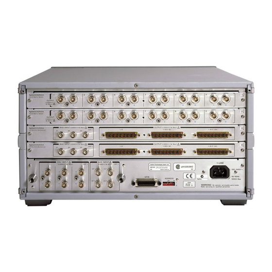
Product Description Agilent E5252A 10´12 Matrix Switch is a 10-input to 12-output switching matrix card for Agilent E5250A Low Leakage Switch Mainframe. The E5252A is designed for semiconductor dc parametric measurement applications that need to switch some instruments connected to Device Under Test (DUT), or need to scan instrument input/output for many DUTs, automatically. - Page 7 WARNING Do not touch the force and guard terminals of the output connectors while the E5250A is turned on. Dangerous voltages up to the maximum input voltage may be present at the output connectors. Agilent E5252A Installation Guide, Edition 2...
-
Page 8: Installation
1. Disconnect the power cable. 2. Disconnect all cables from input/output terminals. CAUTION When the E5252A is shipped from factory, it has been confirmed that the E5252A satisfies its specifications. But after you install the E5252A into your E5250A, the specifications of your E5250A with the card are not guaranteed. - Page 9 To remove blank panel, do as follows: Loosen the screws on both the left and right edges of the blank panel by using the wrench furnished with the E5252A, then remove the blank panel. • To remove a card, do as follows: a.
- Page 10 After executing the relay test, if the Fail LED turns on, the cause is one of the following: a. The Relay Test Adapter is not connected. b. A plug-in card may be defective. Contact your nearest Agilent Technologies Service Center. Agilent E5252A Installation Guide, Edition 2...
- Page 11 E5252A. To verify the specifications, return the E5250A with the cards installed to your nearest Agilent Technologies Service Center. The performance verification should be done by service personnel who are trained to service the E5250A, and should be performed once a year.
- Page 12 Copyright Ó 1995 Agilent Technologies, Inc. Printed in Japan 01/00 Reorder No. or Manufacturing Manual Part No. Part No. E5252-90000 E5252-90002...