Table of Contents
Advertisement
Quick Links
Advertisement
Table of Contents

Related Manuals for Riken Keiki SD-2500


Summary of Contents for Riken Keiki SD-2500
- Page 1 PT2E-15913 Furnace Gas Monitor SD-2500 Operating Manual (PT2E-159) (PT2-159)
- Page 2 In addition, because this is a safety unit, it is recommended that a regular maintenance and a gas calibration are performed every six months in accordance with the regulations. SD-2500...
-
Page 3: Table Of Contents
<Contents> Outline of the Product ....................1 1-1. Preface ........................1 1-2. Purpose of use ......................1 1-3. Definition of DANGER, WARNING, CAUTION, and NOTE ........1 1-4. Method of confirmation for Standards and Explosion proof specification....Important Notices on Safety ..................3 2-1. -
Page 4: Outline Of The Product
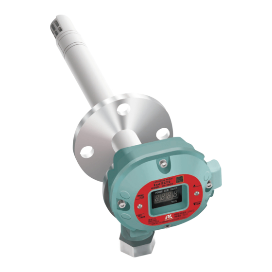
Outline of the Product 1-1. Preface Thank you for choosing our furnace gas monitor SD-2500. Please check that the model number of the product you purchased is included in the specifications on this manual. This manual explains how to use the gas monitor and its specifications. It contains information required for using the gas monitor properly. -
Page 6: Important Notices On Safety
Do not open the lid when applying current. Do not attempt to repair the detector. For the lid, use hexagon socket head bolts specified by RIKEN KEIKI. Do not apply a strong force or shock to the window plate. The explosion-proof performances may be deteriorated due to damages. -
Page 7: Precautions
Since this is a safety unit, a regular maintenance must be performed to ensure safety. Continuing to use the gas monitor without performing a maintenance will deteriorate the sensitivity of the sensor, thus resulting in inaccurate gas detection. SD-2500 - 4 -... -
Page 9: Product Components
Dedicated control key Flange gasket Exhaust air direction nameplate CAUTION Use the supplied dedicated control key to operate the gas monitor. If products other than these accessories are used, key operations cannot be accepted properly. SD-2500 - 6 -... -
Page 11: Block Diagram
Gas alarm contact (ALARM) Contact activation Magnetic operation part • De-energized (MENU/ESC) (▲) (▼) (SET) (De-energized at a normal environment) • ON-ALARM (Closed contact at an alarm time) Sensor Transmitter • 4 – 20 mA transmission SD-2500 - 8 -... -
Page 12: How To Use
Gas sensor part: 0 to +160C <TIIS Specifications> Main unit case part: The detector head must be installed in a stable place where the operating temperature is -20 to +60C and do not change suddenly. Gas sensor part: 0 to +160C SD-2500 - 9 -... -
Page 13: Precautions For System Designing
Take appropriate measures in accordance with the importance of the facilities and the environment. Protection against lightning Provide protection by a lightning arrester (cable arrester). (Although inductive lightning surge can be transmitted through the cable, it is SD-2500 - 10 -... - Page 14 It may be recommended that the surge absorbing part should be attached to the contact for certain load conditions. It must be attached to an appropriate position by checking how the load is activated. SD-2500 - 11 -...
-
Page 17: How To Wire
From Φ9.6 to less than Φ11.0 Φ11 Φ12 From Φ11.0 to less than Φ11.5 Φ12 Φ12 From Φ11.5 to less than Φ12.0 Φ12 Φ14 From Φ12.0 to less than Φ13.0 Φ13 Φ14 Φ13.0 Φ13.5 Φ14 SD-2500 - 14 -... - Page 21 The grounding must be made as D type grounding (below 100 Ω of grounding resistance). <Wiring Example> Connecting to the indicator SD-2500 1 2 3 4 5 RM-593, etc. +24 V Connecting to the upper unit (DCS, PLC)
-
Page 24: How To Operate
2-4.D Password Setting 2-4.E Sensor Fault Alarm Pattern Setting Display various electrical settings. Display This is not typically used by the user. Switch to factory mode Not used Switch to user mode Returns to the user mode. SD-2500 - 21 -... -
Page 28: Operations And Functions
The contact activation is reset automatically when the gas concentration drops below the alarm setpoint value. Alarm setpoint Time Alarm lamp (ALM) Alarm contact (terminal plate 4, 5) Alarm delay time (2 seconds) SD-2500 - 25 -... -
Page 29: Fault Alarm Activation
(initial clear). If the gas monitor has problems and is repeatedly malfunctioning, contact our overseas sales department or local representatives immediately. NOTE For information on malfunctions (error messages), see "9. Troubleshooting". SD-2500 - 26 -... -
Page 32: Maintenance
To maintain the safety operation of the gas monitor, please use our maintenance service. The followings are typical maintenance services. For more information, please contact our overseas sales department or local representative. SD-2500 - 29 -... - Page 33 Replaces parts which are cracked or damaged. (visual diagnosis) Gas Monitor Uses the keys to check the operation of functions and parameters. Operation Check Replacement of Replaces consumable parts, such as a sensor, filter and pump. Consumable Parts SD-2500 - 30 -...
-
Page 34: Regular Maintenance Mode
2-4.D Password Setting 2-4.E Sensor Fault Alarm Pattern Setting Display various electrical settings. Display This is not typically used by the user. Switch to factory Not used. mode Switch to user Returns to the user mode. mode SD-2500 - 31 -... -
Page 43: Parts Replacement
The above replacement intervals are recommendation only. The intervals may change depending on the operating conditions. These intervals do not mean the warranty periods either. The result of the regular maintenance may determine when to replace the parts. SD-2500 - 40 -... -
Page 44: Storage, Relocation And Disposal
For information on readjustment including a gas calibration, please contact our overseas sales department or local representatives. 8-3. Disposal of products When the gas monitor is disposed of, it must be treated properly as an industrial waste in accordance with the local regulations. SD-2500 - 41 -... -
Page 45: Troubleshooting
Check the power supply, and supply the rated supplied to the gas voltage. System monitor. abnormalities Abnormalities of ROM, Please contact our overseas sales department RAM, or EEPROM inside or local representatives. of the gas monitor SD-2500 - 42 -... - Page 46 Because the gas monitor cannot be used under sudden and frequent environmental changes, the user should take some preventive actions to eliminate them. Deteriorated sensor Slow response Replace the sensor with a new one. sensitivity SD-2500 - 43 -...
-
Page 47: Product Specifications
(linear・load resistance less than 300Ω・resolution ability 200division) Transmission cable CVVS worth of shield cable(1.25mm )・3-core or 5-core (by using alarm contact) Transmission Less than 1km distance Power supply DC24V(DC20~26.4V) Power consumption MAX.3W Cabling port Flame proof packing method SD-2500 - 44 -... - Page 48 Direct-insert type Explosion-proof Flame proof structure structure Explosion-proof Ⅱ2G Ex db ⅡC T3 Gb(ATEX) / Ex db ⅡC T3 Gb(IECEx) grade Outer dimension Approx.148(W)×167(H)×458(D)mm(protection excluding) Weight Approx.4.6kg Color Munsell 7.5BG5/2 * Specifications subject to changes without notice. SD-2500 - 45 -...
- Page 49 Initial clear Approx.25sec Operating Sensor:0~+160℃(non-rapidly-vary) temperature Case:0~+50℃(non-rapidly-vary) Structure Direct-insert type Explosion-proof Flame proof structure structure Explosion-proof Ex dⅡC T3 (TIIS<Japan>) grade Outer dimension Approx.148(W)×167(H)×458(D)mm(protection excluding) Weight Approx.4.6kg Color Munsell 7.5BG5/2 * Specifications subject to changes without notice. SD-2500 - 46 -...
-
Page 50: List Of Accessories
Dedicated control key ・・・・・・・・・・・・・・・・・・・・ Depends on ordered quantity of the unit. 1 pce. 1~10 units 2 pcs. 11~20 units 3 pcs. 21~50 units 51 units and above 4 pcs. Flange gasket ・・・・・・・・・・・・・・・・・・・・・・・・・・・ 1pce. Exhaust air direction nameplate ・・・・・・・・・・ 1pce. SD-2500 - 47 -... -
Page 52: Definition Of Terms
Zero suppression A function to cut off the specific drifting that the sensor has. A function which temporarily suspends activation to prevent a false alarm caused Alarm delay time by noise from its outside. SD-2500 - 49 -...
Need help?
Do you have a question about the SD-2500 and is the answer not in the manual?
Questions and answers