Table of Contents

Related Manuals for Riken Keiki GX-3R


Summary of Contents for Riken Keiki GX-3R
- Page 1 PT0E-1767 Portable Gas Monitor GX-3R Operating Manual (PT0-164) 2-7-6 Azusawa, Itabashi-ku, Tokyo, 174-8744, Japan Phone : +81-3-3966-1113 Fax : +81-3-3558-9110 E-mail : intdept@rikenkeiki.co.jp Web site : http://www.rikenkeiki.co.jp/...
-
Page 2: Table Of Contents
Contents 1 Product Overview ............................4 1-1. Introduction ............................4 1-2. Intended use ............................4 1-3. DANGER, WARNING, CAUTION, and NOTE ..................6 1-4. Checking standards and explosion-proof specifications ............... 6 2 Important Safety Information ......................... 7 2-1. Danger information ..........................7 2-2. - Page 3 6-4-6. Lunch break: ON/OFF ......................54 6-4-7. Confirmation beep setting ......................55 6-4-8. LCD lighting time setting ......................57 6-4-9. Key tone: ON/OFF ........................57 6-4-10. Display mode item display: ON/OFF ..................58 6-4-11. Date and time setting ......................58 6-4-12.
-
Page 4: Product Overview
Product Overview 1-1. Introduction Thank you for your purchase of the GX-3R Portable Gas Monitor (“product” hereinafter). First, please confirm that the model number of the product you purchased matches the model number of the product covered by this manual. - Page 5 <List of detection target gases (installed sensor models) by type> Detection target gases (installed sensor models) Carbon Combustible Hydrogen Carbon Carbon Type Oxygen monoxide/hydrogen sulfide monoxide monoxide (ESR-X13P) sulfide <HC > (ESR-A13i) (ESR-A13P) (ESR-A1CP)* (NCR-6309) (ESR-A1DP) Type A ...
-
Page 6: Danger, Warning, Caution, And Note
1-3. DANGER, WARNING, CAUTION, and NOTE This manual uses the following headings to ensure safe and effective work: This indicates situations in which improper handling may result in fatal or DANGER serious injury to persons or serious damage to property. This indicates situations in which improper handling may result in serious WARNING injury to persons or serious damage to property. -
Page 7: Important Safety Information
Important Safety Information To maintain the performance of the product and to ensure safe use, always observe the following DANGER, WARNING, and CAUTION instructions. 2-1. Danger information DANGER Explosion-proofing Do not modify or alter the circuitry or configuration. When measuring oxygen concentrations, do not measure anything but mixtures of air and combustible or toxic gases. -
Page 8: Warning Information
2-2. Warning information WARNING If an abnormality is discovered in the product If an abnormality is discovered in the product, contact Riken Keiki immediately. Visit our website for information on the nearest Riken Keiki office. Website: http://www.rikenkeiki.co.jp/ Sensor handling ... -
Page 9: Caution Information
2-3. Caution information CAUTION Do not use the product in locations where it may be exposed to oil or chemicals, etc. ‧ Avoid using the product in locations where the product may be splashed with liquids such as oil and chemicals. - Page 10 Doing so may discolor or damage the surfaces of the product. ‧ After a period of extended storage, be sure to perform calibration before resuming use. For information on readjustment including calibration, please contact Riken Keiki. - 10 -...
-
Page 11: Safety Information
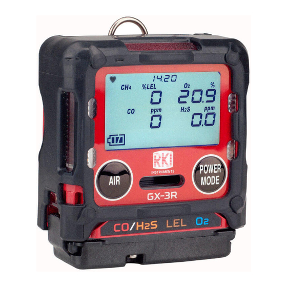
Overview The GX-3R can measure up to 4 gases using 3 sensors. The GX-3R measures the combustible gases (LEL), oxygen (O2), hydrogen sulfide (H2S), and carbon monoxide (CO). This model displays measurement results on an LCD and issue gas alarms (via LED and buzzer) as needed. - Page 12 WARNING Do not attempt to disassemble or modify the instrument. The combustible gas sensor NCR-6309, to measure LEL, is the only part of this Gas Monitor system with flame - proof construction. This product is an explosion-proof product and is not to be disassembled or modified with the exception of specified parts.
- Page 13 Instruments No. INST. No. 00 0 000 0000 00 A: Year of manufacture (0 to 9) B: Month of manufacture (1 to 9 for Jan.-Sep.; XYZ for Oct., Nov., Dec.) C: Manufacturing lot D: Serial number E: Factory codes <Japan Ex specification> Explosion proof structure Intrinsically safe explosion-proof construction Explosion proof class...
-
Page 14: Product Configuration
3-1. Main unit and standard accessories Open the box and packaging and inspect the product and accessories. If anything is missing, contact Riken Keiki. Main unit For detailed information on the names and functions of product parts and the LCD display, see “3-2. Part names and functions”... -
Page 15: Standard Accessories
Standard accessories AC adapter Rubber protection ×1 cover ×1 Protects the product from impact if it is hit by something or dropped. Alligator clip Calibration adapter ×1 (simple type) ×1 Allows attaching the product to a pocket. Used to perform gas * ATEX/IECEx calibration and bump specification only... -
Page 16: Part Names And Functions
3-2. Part names and functions This section describes the names and functions of the various parts of the main unit and the LCD display. Main unit (4), (5) Name Main function LCD display Displays information such as gas type and gas concentration. Turns the power on and off. -
Page 17: Lcd Display
NOTE In this operating manual, buttons that have multiple functions are described as follows in the operational procedures: Example: “POWER/MODE button” is described as follows: POWER button when turning the power on and off MODE button when confirming settings LCD display Name Main function... -
Page 18: Alarm Activation
Alarm Activation 4-1. Gas alarm activation <Alarm types> A “gas alarm” is triggered if the concentration of the detected gas reaches or exceeds the alarm setpoints shown in the following table. (Self-latching) Gas alarm types include the first alarm (WARNING), second alarm (ALARM), third alarm (ALARM H), TWA alarm, STEL alarm, OVER alarm (over scale), and M OVER alarm (minus sensor failure). - Page 19 <Gas alarm buzzer sounding and lamp flashing patterns> When a gas alarm occurs, the user is notified by the buzzer sounding, alarm LED array flashing, and vibration, in two stages. The individual operations are as follows: Alarm First Second Third STEL OVER M OVER...
-
Page 20: Fault Alarm Activation
Sensor abnormality If a fault alarm occurs, determine the cause and take appropriate action. If the problem lies with the product and the fault occurs repeatedly, contact Riken Keiki immediately. NOTE For more information on malfunctions (error messages), see “... -
Page 21: Usage Instructions
Usage Instructions 5-1. Before using the product The operating precautions apply to both first-time users and those who have previously used the product. Ignoring these precautions may damage the product and result in inaccurate gas detection. 5-2. Preparing startup Check the following before starting gas detection: ・... - Page 22 CAUTION Be sure to turn off the power for the product before charging the battery. Do not use the product while charging the battery. The measurements obtained will not be correct. Additionally, doing so will degrade the battery more quickly and reduce battery life. ...
-
Page 23: Startup
5-3. Startup When the power is turned on, various settings including date and time and alarm setpoints are displayed, and then the measuring mode screen is displayed. Turning on the power Hold down the POWER button (for at least 3 seconds) until the buzzer blips. The power turns on. -
Page 24: Screen Transition From Powering On To Displaying Measurement Screen
Screen transition from powering on to displaying measurement screen When the power is turned on, the LCD display changes automatically as shown below before the measurement screen is displayed. <Display examples: Default settings> ( about 40 seconds ) Date and time display Calibration notification Calibration expiration date display screen... - Page 25 -” appears in the concentration display area of the gas for which the sensor abnormality occurred, and detection will not be possible for that gas type. Contact Riken Keiki immediately. After startup, perform “5-4. Air calibration” on page 27.
- Page 26 NOTE If there is an abnormality in the built-in clock, a “FAIL CLOCK” fault alarm may be triggered. If this occurs, press the MODE button. The fault alarm will be temporarily reset, and measurement will be started with the clock time remaining incorrect. Lunch break When the lunch break setting is enabled, the screen is displayed with a five-second countdown to allow the user to confirm whether to retain the TWA and PEAK values from the last time the power...
-
Page 27: Air Calibration
5-4. Air calibration Air calibration refers to zero adjustment required to ensure accurate measurement of gas concentrations. WARNING When air calibration is performed in the atmosphere, check the atmosphere for freshness before starting. The presence of interference gases will make it impossible to perform air calibration correctly and potentially result in hazardous conditions in the event of actual gas leaks. -
Page 28: Gas Detection
5-5. Gas detection DANGER If measuring inside manholes or enclosed spaces, never lean over or look into the manhole or enclosed space. There is a danger that oxygen-deficient air or other gases may be discharged from such locations. WARNING ... -
Page 29: Measurement Mode
5-5-2. Measurement mode In measurement mode, read the values on the LCD display. Combustible gas Oxygen (%LEL) Carbon Hydrogen monoxide sulfide Display example CAUTION Note that if combustible gas sensors are used in an environment where silicone compounds, halides, high concentrations of sulfides, or high concentrations of solvent gases are present, sensor life may be reduced, sensitivity to combustible gases may deteriorate, and accurate readings may not be obtained. - Page 30 The carbon monoxide sensor (ESR-A1CP) includes a correction function to reduce interference due to hydrogen. This function works for hydrogen concentrations up to 2,000 ppm. If hydrogen is detected at a concentration of 2,000 ppm or higher, “H2” and “rich” are displayed alternately in the concentration display area.
-
Page 31: Turning Off The Power
5-6. Turning off the power CAUTION If the concentration display does not return to zero (or 20.9 % for the oxygen concentration display) after measurement is completed, allow the product to stand in fresh air until the display returns to zero before turning off the power. Hold down the POWER button. -
Page 32: Setting Procedure
Setting Procedure 6-1. Display mode Display mode lets users review and change various display settings and perform other operations. Changed settings are saved. 6-1-1. Displaying display mode Press the MODE button on the measurement mode screen. Pressing the MODE button displays the various screens in sequence. - Page 33 Screen notation Display contents LCD display Reference page (Setting item) Displays the STEL value since the power was turned on. The STEL value refers to the sum STEL of 15 pieces of average value (STEL display) data for measured values over a ----- * Displays only CO and period of 60 seconds divided by...
-
Page 34: Display Mode Settings
6-2. Display mode settings Switch to display mode from the measurement screen, and check and change settings in display mode. 6-2-1. Clearing PEAK value display This clears the PEAK value (the maximum gas concentration or minimum oxygen concentration measured since the power was turned on). Press the MODE button on the measurement screen to display the PEAK screen. -
Page 35: Combustible Conversion Gas Selection
6-2-2. Combustible conversion gas selection Combustible gas measurements can be displayed as a concentration converted to a gas registered in the product. The following combustible gases can be converted: <Combustible conversion gas list> Calibration gas Conversion Gas name conversion when Conversion gas displayed conversion is... - Page 36 The concentration display when converted should be treated as approximate. To display accurate concentrations, you must perform calibration using the target gas. To perform span adjustment using the target gas, please contact Riken Keiki. For information on the list of gases that can be converted, see the “Combustible conversion gas list”...
-
Page 37: Long-Life Battery Setting
6-2-3. Long-life battery setting This enables/disables the long-life battery setting. The default setting is “OFF”. When set to “ON”, the combustible gas concentration is refreshed every 15 seconds instead of every 5 seconds. NOTE The setting is retained even when the power is turned off. ... -
Page 38: Calibration Data Display
6-2-4. Calibration data display This displays the calibration date. NOTE Calibration data is not displayed if the calibration expiration date setting is disabled in user mode. Calibration data is displayed only on general ATEX/IECEx specification. Press the MODE button on the measurement screen several times to display the CAL DATA screen. -
Page 39: Bump Data Display
6-2-5. Bump data display This displays the bump test date. NOTE Bump data is not displayed if the bump test expiration date setting is disabled in user mode. After the gas calibration, the date is updated automatically. 1 Press the MODE button on the measurement screen several times to display the BUMP DATA screen. -
Page 40: Alarm Setpoint Display
6-2-5. Alarm setpoint display This allows alarm setpoints to be displayed and testing of LED, buzzer, and vibrator operations. NOTE TWA and STEL are displayed only on models that detect gases other than combustible gases and oxygen. 1 Press the MODE button on the measurement screen several times to display the ALARM-PT screen. -
Page 41: User Mode
6-3. User mode User mode lets you set the date and time, alarm setpoints, and other settings. 6-3-1. Displaying user mode With the power turned off, press the AIR button and POWER button at the same time. Release the buttons when the buzzer blips. -
Page 42: User Mode Settings
6-3-2. User mode settings Reference Screen display (setting item) LCD display page BUMP (Bump test) P. 44 GAS CAL (Calibration) P. 44 CAL SET (Calibration expiration date setting) P. 44 * Displayed on general ATEX/IECEx specification only BUMP SET (Bump test setting) P. - Page 43 Reference Screen display (setting item) LCD display page DATE (Date and time setting) P. 58 PASSWORD (Password setting) P. 59 ROM/SUM (ROM/SUM display) P. 60 START (Measurement start) - 43 -...
-
Page 44: User Mode Settings
The product’s GAS CAL mode allows automatic calibration (AUTO CAL) using preset gas concentrations in addition to air calibration. Span adjustment requires dedicated tools and a calibration gas. Contact Riken Keiki. After successful gas calibration, the screen will automatically move to the measurement start screen. - Page 45 Setting item LCD display Reference page <Calibration expiration date: ON/OFF> CAL RMDR P. 45 <Calibration expiration date interval> CAL INT P. 46 <Operation after calibration date CAL EXPD expired> P. 46 ESCAPE <Calibration expiration date: ON/OFF> This lets you enable and disable the calibration expiration date. Press the AIR button to select “CAL RMDR”, then press the MODE button.
- Page 46 <Calibration expiration date interval> This lets you select the number of days until the calibration expires. Press the AIR button to select “CAL INT”, then press the MODE button. Press the AIR button to select the number of days for calibration expiration.
-
Page 47: Bump Test Setting
6-4-4. Bump test setting This lets you set the various conditions for bump testing. <Bump test setting menu> Press the AIR button on the user mode menu to select “BUMP SET”, then press the MODE button. The bump test menu screen is displayed. Press the AIR button to select the required setting, then press the MODE button. - Page 48 <Bump time selection> This sets the time for introducing the test gas. Press the AIR button to select “SETTINGS”, then press the MODE button. The bump test setting menu is displayed. Press the AIR button to select “GAS TIME”, then press the MODE button. The bump time is displayed.
- Page 49 <Bump tolerance selection> This sets the threshold for checking the test gas. Gases other than oxygen: Calibration concentration ± (calibration concentration × tolerance) Oxygen: Calibration concentration ± (difference between calibration concentration and 20.9% × tolerance) Press the AIR button to select “SETTINGS”, then press the MODE button.
- Page 50 <Calibration after bump test: ON/OFF> This enables/disables the function for automatic calibration if a bump test fails. Press the AIR button to select “SETTINGS”, then press the MODE button. The bump test setting menu is displayed. Press the AIR button to select “AUTO CAL”, then press the MODE button.
- Page 51 <Bump expiration date interval selection> This sets the interval until the bump test expiration date notification is given after a bump test. Press the AIR button to select “BUMP INT”, then press the MODE button. You can select the number of days until the bump test expiration date.
-
Page 52: Alarm Setpoint Setting
6-4-5. Alarm setpoint setting This section describes the settings for the first to third alarm setpoints, STEL alarm setpoint, and TWA alarm setpoint and how to restore the default settings. <Alarm setpoint setting> Alarm setpoints can be set using one-digit units. Detection target gas 1 digit Lower limit... - Page 53 NOTE For information on how to reset settings, see “Resetting alarm setpoints” on page 53. The alarm setpoint reset screen may not appear if the product is not set correctly. If this occurs, contact Riken Keiki. For more information on alarm setpoints, see “4 Alarm Activation”...
-
Page 54: Lunch Break: On/Off
6-4-6. Lunch break: ON/OFF This lets you enable and disable the lunch break function. The lunch break function retains TWA and PEAK values from the last time the power was turned off and loads them to continue measurement the next time the power is turned on. Press the AIR button on the user mode menu to select “LUNCH”, then press the MODE button. -
Page 55: Confirmation Beep Setting
6-4-7. Confirmation beep setting This function provides an audible indication of whether the product is operating normally. The buzzer sounds at preset intervals while measurement is underway. The following functions can also be operated with "BUMP / CAL", "ALM ALRT" and "B / C / ALM”. 1. - Page 56 NOTE Once setting is complete, press the AIR button to select “ESCAPE”, then press the MODE button. The display returns to the user mode menu. <Beep operation setting> This lets you set the confirmation beep operation. Press the AIR button to select “BEEP SEL”, then press the MODE button.
-
Page 57: Lcd Lighting Time Setting
6-4-8. LCD lighting time setting This lets you set the duration for which the LCD display remains lit. Press the AIR button on the user mode menu to select “BL TIME”, then press the MODE button. The backlight lighting time setting screen is displayed. -
Page 58: Display Mode Item Display: On/Off
6-4-10. Display mode item display: ON/OFF This lets you set whether display mode items that can be set are displayed or hidden. When set to OFF, items such as “HC GAS” (combustible conversion gas selection) are not displayed in display mode. Press the AIR button on the user mode menu to select “DISP SET”, then press the MODE button. -
Page 59: User Password Setting
6-4-12. User password setting This lets you protect access to user mode using a password. The password can be set as a four-digit number in the range 0000 to 9999. Press the AIR button on the user mode menu to select “PASSWORD”, then press the MODE button. -
Page 60: Rom/Sum Display
6-4-13. ROM/SUM display This displays the program number and SUM value of the product. * This is not normally used by the user. Press the AIR button on the user mode menu to select “ROM/SUM”, then press the MODE button. The ROM/SUM screen is displayed. -
Page 61: Maintenance
The built-in sensors have finite service lives and must be replaced regularly. If the sensors cannot be calibrated using span adjustment, the readings are not restored after air calibration, or the readings fluctuate, the sensors are at the end of their life. Contact Riken Keiki for replacement. -
Page 62: Maintenance Service
Our certified service engineers have expert knowledge of the dedicated tools used for these services, along with expertise in products. Please take advantage of the Riken Keiki maintenance service to maintain safe operation of the product. -
Page 63: Calibration
The product can be calibrated using automatic calibration with preset gas concentrations in addition to air calibration. Span adjustment requires dedicated tools and a calibration gas. Contact Riken Keiki. CAUTION Do not use lighter gas to check the sensitivity of the product. Constituents in the lighter gas may degrade sensor performance. - Page 64 <Gas supply method> Attach a calibration adapter (simple type) to the product, connect the gas sampling bag as shown in the figure below to introduce gas at a flow rate of 250 mL/min, and wait 60 seconds after the reading increases before calibrating.
-
Page 65: Calibration Setting Menu
7-2-2. Calibration setting menu This section describes “Air calibration”, “Auto calibration concentration setting”, “Auto calibration cylinder setting”, “Auto calibration”, and “CO zero calibration”. Press the AIR button on the user mode menu to select “GAS CAL”, then press the MODE button. The calibration menu screen is displayed. -
Page 66: Air Calibration
7-2-3. Air calibration WARNING When air calibration is performed in the atmosphere, check the atmosphere for freshness before starting. The presence of interference gases will make it impossible to perform zero adjustment correctly and potentially result in hazardous conditions in the event of actual gas leaks. CAUTION ... -
Page 67: Auto Calibration
The current concentration after air calibration appears. The display returns to the calibration menu screen. “FAIL” is displayed if calibration was unsuccessful. “END” appears and the display returns to the calibration menu screen. NOTE If air calibration fails, “FAIL” appears next to the measurement for the faulty sensor together with “AIR CAL”. - Page 68 “PASS” is displayed if auto calibration was successful. “FAIL” is displayed if calibration was unsuccessful. The concentration after auto calibration is displayed. On Japan Ex specification only, the concentration and sensor reserve value after auto calibration are displayed after auto calibration has been successfully performed.
-
Page 69: Switch From Auto Calibration To Measurement Start Screen
7-2-5. Switch from AUTO calibration to measurement start screen In this section, it explains about switchment from AUTO calibration to measurement start screen. Press the AIR button and select “AUTO CAL” and press the MODE button. AUTO calibration screen is displayed. Press the AIR button and select “START”, then press the MODE button. -
Page 70: Auto Calibration Cylinder Setting
7-2-6. Auto calibration cylinder setting This section describes how to set gas groups (cylinders) for calibration. Five cylinders can be set as A to Press the AIR button to select “AUTO CAL”, then press the MODE button. The auto calibration screen is displayed. Press the AIR button and select “CYL SEL”, then press the MODE button. -
Page 71: Auto Calibration Gas Concentration Selection
7-2-7. Auto calibration gas concentration selection This section describes how to select the calibration gas concentration for the individual sensors. Calibration gas concentration can be set in one-digit units within the setting range. <Calibration gas concentration setting range> Detection target gas Sensor model Calibration gas 1 digit... -
Page 72: Bump Test
7-3. Bump test The product includes a function for performing a bump test (function check). 7-3-1. Perform bump test (BUMP TEST) A bump test can be performed for gas types selected from cylinders A to E. Prepare a bump test gas in the same way as for the calibration gas (P. -
Page 73: Switching From Bump Test (Bump Test) To Measurement Start Screen
CAUTION For models with a combustible gas sensor installed, the screen shown on the right may be displayed if calibration is performed after a bump test failure. If this screen is displayed, some combustible gases cannot be converted using the combustible gas conversion function. For information on the types of gases that cannot be converted, see “6-2-2. -
Page 74: Cleaning Instructions
7-4. Cleaning instructions Clean the product if it becomes excessively dirty. Be sure to turn off the power before cleaning, and wipe clean using a rag or cloth soaked in water and firmly wrung out. Do not clean using water, organic solvents or commercially available cleaners for cleaning, as these may cause the product to malfunction. -
Page 75: Parts Replacement
Battery cycles * A functional check by a qualified service engineer is required after replacement. To ensure safety and the stable operation of the product, request checking by a qualified service engineer. Contact Riken Keiki to request checking. NOTE The above replacement intervals are guidelines only. Replacement intervals may vary depending on actual operating conditions. -
Page 76: Filter Replacement
7-5-2. Filter replacement The dust filter and interference gas removal filters are consumables. Check the extent of contamination and replace them regularly. <Dust filter replacement procedure> Loosen the two screws on the underside of the main unit and release Screws the two tabs. - Page 77 Be sure to use only dust filters and interference gas removal filters specifically intended for use with the product (GX-3R). Use of non-approved parts may adversely affect gas detection performance and allow water to get inside the product.
- Page 78 Be sure to use only dust filters and interference gas removal filters specifically intended for use with the product (GX-3R). Use of non-approved parts may adversely affect gas detection performance and allow water to get inside the product.
-
Page 79: Storage And Disposal
Perform calibration if the product is used again after a period in storage. CAUTION Contact Riken Keiki to request readjustment and gas calibration. If there is a temperature difference of 15 °C or more between the storage and usage locations, turn on the power and allow the product to stand for about 10 minutes in a similar environment to the usage location to acclimatize before performing air calibration in fresh air. -
Page 80: Product Disposal
8-3. Product disposal Dispose of the product as industrial waste (incombustible) in accordance with local regulations. WARNING Never attempt to disassemble electrochemical type sensors, as they contain electrolyte. Electrolyte may cause inflammation if it comes into contact with the skin and may cause blindness if it comes into contact with the eyes. -
Page 81: Troubleshooting
Provide fresh air. surrounded by fresh air. Air calibration is not possible. <FAIL SENSOR> The sensor sensitivity has Contact Riken Keiki to request sensor degraded. replacement. The bump test gas Check to confirm that the bump test gas concentration setting differs... - Page 82 <FAIL SENSOR> (only for ESR-A1CP H2) perform gas calibration again. The sensor sensitivity has Contact Riken Keiki to request sensor degraded. replacement. Symptoms Cause Action <Screen display>...
-
Page 83: Reading Abnormalities
<Screen display> Sensor drift Perform air calibration. It is difficult to completely eliminate the effects of Presence of interference interference gases. Contact Riken Keiki for The reading rises gases information on countermeasures, such as (or drops) and interference gas removal filters. -
Page 84: Product Specifications
Product Specifications 10-1. Specifications list <Common specifications> Concentration LCD digital (7 segments + 14 segments + icons) display Detection method Diffusion type Clock, battery level, operation status Displays Buzzer volume Approx. 95 dB (mean value at 30 cm) Gas alarm Lamp flashing, continuous modulating buzzer sounding, gas concentration indication display blinking, vibration... - Page 85 ATEX II1G Ex da ia IIC T4 Ga / IM1 Ex da ia I Ma ( With combustible gas sensor) II1G Ex ia IIC T4 Ga / IM1 Ex ia I Ma ( No combustible gas sensor) IECEx Explosion-proof Ex da ia IIC T4 Ga / Ex da ia I Ma ( With combustible gas sensor) class Ex ia IIC T4 Ga / Ex ia I Ma ( No combustible gas sensor) Japan Ex...
- Page 86 <Individual sensor specifications> Combustible gas Detection Item target gas Isobutane (i-C ) or Methane (CH Detection range 0 to 100 %LEL 1 digit 1 %LEL 1st alarm: 10 %LEL Alarm setpoint 2nd alarm: 25 %LEL (General ATEX/IECEx 3rd alarm: 50 %LEL specification) OVER alarm: 100 %LEL 1st alarm: 10 %LEL...
-
Page 87: Accessory List
10-2. Accessory list Standard accessories (general ATEX/IECEx specification) Part name Part number Hand strap 0888 0605 90 Belt clip (with attachment screw) 4777 9202 40 Rubber protection cover 4777 4161 10 AC adapter 2594 0898 30 EU plug 2594 0933 60 Calibration adapter (simple type) 4777 9307 40 Standard accessories (Japan Ex specification) -
Page 88: Appendix
NOTE The data logger management program (sold separately) is required to check data recorded using the data logger function. Contact Riken Keiki for more information. The data logger provides the following five functions: (1) Interval trend Records the changes in measured concentration from when the power is turned on until it is turned off. - Page 89 (4) Trouble event Records fault alarm occurrences as events. This function records the time when the fault alarm was triggered, the measurement target gas, device information, and the type of trouble event. Records the 100 most recent events. If the number of events exceeds 100, the oldest data will be overwritten by the latest data. (5) Calibration history Records data when calibration is performed.
-
Page 90: 100 %Lel = Ppm Conversion List
100 %LEL = ppm conversion list The following table shows the standard conversion for 100 %LEL and ppm: Standard Methane 50,000 ppm 44,000 ppm 44,000 ppm Isobutane i-C4H10 18,000 ppm 13,000 ppm 15,000 ppm Hydrogen 40,000 ppm 40,000 ppm 40,000 ppm Methanol CH3OH 55,000 ppm... -
Page 91: Revision Or Abolition History
Revision or Abolition History Edition Revision Issue date First issue 2019/2/27 Words added 2019/3/7 Clerical corrections 2019/3/22 Clerical corrections, Words added 2019/4/11 Clerical corrections 2019/5/8 Add item 2019/7/1 Clerical corrections, 2-4/5-3/6-4/7-2 corrections 2019/10/10 Clerical corrections, change dust filter, add standard accessory 2019/12/1 - 91 -... - Page 92 - 92 -...
- Page 93 - 93 -...
Need help?
Do you have a question about the GX-3R and is the answer not in the manual?
Questions and answers