
Related Manuals for Riken Keiki GX-2012 Series


Summary of Contents for Riken Keiki GX-2012 Series
- Page 1 PT0E-1075 Portable Multi-Gas Monitor GX-2012 Series GX-2012 GX-2012GT Operating Manual (PT0-107)
-
Page 2: Safety Information
Safety information <ATEX/IECEx specifications> The Portable Gas Monitor Model GX-2012 is a gas monitor designed to provide continuous exposure monitoring of combustible gas (LEL,VOL), oxygen (O2), toxic gas such as carbon monoxide (CO) and hydrogen sulfide (H2S) in hazardous environments. Model GX-2012GT is a gas monitor designed to provide continuous exposure monitoring of combustible gas (ppm,LEL,VOL), oxygen (O2), toxic gas such as carbon monoxide (CO). -
Page 3: Table Of Contents
<Contents> Outline of the Product ....................2 1-1. Preface ........................2 1-2. Purpose of use ......................2 1-3. Definition of DANGER, WARNING, CAUTION, and NOTE ........2 Important Notices on Safety ..................3 2-1. Danger cases ......................3 2-2. Warning cases ......................5 2-3. -
Page 4: Outline Of The Product
Outline of the Product 1-1. Preface Thank you for choosing our portable multi-gas monitor GX-2012 series. Please check that the model number of the product you purchased is included in the specifications on this manual. This manual explains how to use the gas monitor and its specifications. It contains information required for using the gas monitor properly. -
Page 5: Important Notices On Safety
2 Important Notices on Safety 2-1. Danger cases Important Notices on Safety 2-1. Danger cases DANGER Nameplate location Main unit Battery unit About explosion-proof of main unit Do not modify or change the circuit or structure, etc. When measuring the oxygen concentration, do not measure anything but a mixture of air and combustible gases or vapors and toxic gases. - Page 6 Product model: Main unit GX-2012,GX-2012GT Dry battery unit BUD-2012 Lithium ion battery unit BUL-2012,BUL-2012(G1) Manufacture: RIKEN KEIKI Co., LTD. Explosion-proof grade: ExiaⅡCT4X(GX-2012,GX-2012GT) ExiaⅡCT4(BUD-2012,BUL-2012,BUL-2012(G1)) Ambient temperature: -20℃~+50℃ Warnings: Inhibit to take off battery unit in non-hazardous area. (GX-2012,GX-2012GT) Inhibit to take off dry battery in non-hazardous area. (GX-2012,GX-2012GT,BUD-2012) Powered by three series AA size alkaline batteries, model LR6 by TOSHIBA.
-
Page 7: Warning Cases
2 Important Notices on Safety 2-2. Warning cases 2-2. Warning cases WARNING Sampling point pressure The gas monitor is designed to draw gases around it under the atmospheric pressure. If excessive pressure is applied to the gas inlet and outlet (GAS IN, GAS OUT) of the gas monitor, detected gases may be leaked from its inside, thus leading to danger. -
Page 8: Precautions
2 Important Notices on Safety 2-3. Precautions 2-3. Precautions CAUTION Do not use the gas monitor where it is exposed to oil, chemicals, etc. Do not submerge the gas monitor under water on purpose. Do not use in a place where the gas monitor is exposed to liquids such as oil and chemicals. ... - Page 9 2 Important Notices on Safety 2-3. Precautions CAUTION Others Pressing buttons unnecessarily may change the settings, preventing alarms from activating correctly. Operate the gas monitor using only the procedures described in this operating manual. Do not drop or give shock to the gas monitor. The water-proof and explosion-proof properties and accuracy may be deteriorated.
-
Page 10: Product Components
3-1. Main unit and standard accessories Product Components 3-1. Main unit and standard accessories After opening the package, check the main unit and accessories. If anything in the following list is not included, contact RIKEN KEIKI. <Main Unit> <Standard Accessories> Alkaline dry batteries: 3... - Page 11 Product model: Main unit GX-2012,GX-2012GT Dry battery unit BUD-2012 Lithium ion battery unit BUL-2012,BUL-2012(G1) Manufacture: RIKEN KEIKI Co., LTD. Explosion-proof grade: ExiaⅡCT4X(GX-2012,GX-2012GT) ExiaⅡCT4(BUD-2012,BUL-2012,BUL-2012(G1)) Ambient temperature: -20℃~+50℃ Warnings: Inhibit to take off battery unit in non-hazardous area. (GX-2012,GX-2012GT) Inhibit to take off dry battery in non-hazardous area. (GX-2012,GX-2012GT,BUD-2012)
-
Page 12: Names And Functions For Each Part
3 Product Components 3-2. Names and functions for each part 3-2. Names and functions for each part <Outline Drawing> (Main Unit) (10) Gas inlet (11) Gas outlet (14) Filter case (3) Alarm LED (1) LCD (2) Buzzer sound arrays (13) Sensor cover display opening (12) Holes for... - Page 13 3 Product Components 3-2. Names and functions for each part CAUTION Do not jab the buzzer sound opening with a sharp-pointed item. The unit may malfunction or get damaged, allowing water or foreign substance, etc. to get inside. Do not remove the panel sheet on the surface. The water-proof and dust-proof performances will be deteriorated.
-
Page 14: Lcd Display
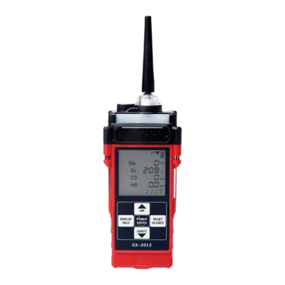
3 Product Components 3-2. Names and functions for each part <LCD Display> GX-2012 GX-2012GT <Normal Mode> (1) Pilot indicator (2) Pump operations status indicator (3) Battery level icon (4) Combustible gas concentration (5) Oxygen concentration (6) Carbon monoxide concentration (7) Hydrogen sulfide concentration (8) Clock display Pilot indicator... - Page 15 3 Product Components 3-2. Names and functions for each part <LCD Display> GX-2012GT <Leak Check Mode> (1) Pilot indicator (2) Pump operation status indicator (3) Battery level icon (5) Combustible gas bar display (4) Combustible gas concentration (6) Leak check full scale value display Pilot indicator Displays the operating status.
-
Page 16: How To Use
4 How to Use 4-1. Before using the gas monitor How to Use 4-1. Before using the gas monitor Not only the first-time users but also the users who have already used the product must follow the operating precautions. Ignoring the precautions may damage the gas monitor, resulting in inaccurate gas detection. 4-2. - Page 17 4 How to Use 4-2. Preparation for start-up <Attaching Batteries> When the gas monitor is used for the first time, or when the battery level is low, attach new AA alkaline batteries. DANGER Do not modify or change the circuit or structure, etc. ...
- Page 18 4 How to Use 4-2. Preparation for start-up <Charging Batteries> (When the option unit BUL-2012, BUL-2012(G1) are used) When the gas monitor is used for the first time, or when the battery level is low, be sure to use the dedicated charger to charge the batteries.
- Page 19 Taper nozzle <Connecting Taper Nozzle> Connect the taper nozzle to the gas inlet of the gas monitor. Gas inlet * Belt clip is optional. CAUTION Use only the parts specified by RIKEN KEIKI on this gas monitor.
-
Page 20: Basic Operating Procedures
4 How to Use 4-3. Basic operating procedures 4-3. Basic operating procedures <GX-2012> Normally, the detection mode is used for normal operations. (The detection mode is activated after the power is turned on.) (* Operations are slightly different depending on the type) <<Detection Mode>>... - Page 21 4 How to Use 4-3. Basic operating procedures <GX-2012GT> Normally, after the power is turned on, the detection mode (normal mode or leak check mode) is selected for use. (* Operations are slightly different depending on the type) <<Mode Selection>> ENTER <<Detection Mode>>...
-
Page 22: How To Start The Gas Monitor
4 How to Use 4-4. How to start the gas monitor 4-4. How to start the gas monitor <<GX-2012 Start-up Procedure>> (* Operations are slightly different depending on the type) Keep the POWER switch pressed for three seconds or more. All LCDs light up. - Page 23 ---, and start gas detection. However, notify the abnormality to RIKEN KEIKI promptly. Gas for which there was an abnormality in the sensor cannot be detected. However, the alarm cannot be reset if there is an abnormality in all the sensors.
- Page 24 4 How to Use 4-4. How to start the gas monitor <<GX-2012GT Start-up Procedure>> (* Operations are slightly different depending on the type) Press the POWER switch for at least 3 seconds. All LCDs light up. Alarm lamp lights up. Buzzer sounds once (Beep).
- Page 25 ---, and start gas detection. However, notify the abnormality to RIKEN KEIKI promptly. Gas for which there was an abnormality in the sensor cannot be detected. However, the alarm cannot be reset if there is an abnormality in all the sensors.
-
Page 26: How To Detect
4 How to Use 4-5. How to detect 4-5. How to detect In each mode, put the taper nozzle close to the detection area and take the reading on the display. (* Operations are slightly different depending on the type) GX-2012 GX-2012GT <Normal Mode>... - Page 27 4 How to Use 4-5. How to detect WARNING The gas monitor is designed to draw gases around it under the atmospheric pressure. If excessive pressure is applied to the gas inlet and outlet (GAS IN, GAS OUT) of the gas monitor, detected gases may leak out from its inside and may cause dangerous conditions.
- Page 28 4 How to Use 4-5. How to detect <Leak Check Mode>(GX-2012GT <Leak Check Mode>) Depending on the concentration of combustible gas, bar display is increased or decreased and the buzzer sounds intermittent beeps. As the concentration becomes higher, the interval of intermittent beeps of the buzzer becomes shorter.
- Page 29 4 How to Use 4-5. How to detect <Manual Memory> (GX-2012, GX-2012GT <Normal Mode>) Any instantaneous value during measurement can be recorded. Up to 256 points of data can be recorded. When the number of recorded data points reaches the maximum, recorded data will be overwritten, starting from the oldest data.
- Page 30 4 How to Use 4-5. How to detect <About Auto Range Switching Point> (GX-2012 TYPE-A, E, GX-2012GT <Normal Mode>(*Only the types which detect high-concentration combustible gases <vol%>) If Auto Range is set on a type with the vol% range for combustible gases, the display is automatically switched to the vol% range when the concentration of a detected combustible gas exceeds 100% LEL.
-
Page 31: Modes
4 How to Use 4-6. Modes 4-6. Modes (GX-2012, GX-2012GT <Normal Mode>) Details on each mode are provided as follows. (* Operations are slightly different depending on the type) Mode Item LCD display Details Detection Display Normal state. Mode Air Calibration Air CAL Perform the zero adjustment. - Page 32 4 How to Use 4-6. Modes Mode Item LCD display Details Display/Setting Clear Log Data LG CLEAR Clears the log data. Mode User ID UId SEL Displays and selects the ID. Display/ Displays an ID if it has been set in advance. Selection Default setting is ----.
-
Page 33: Air Calibration Mode
4 How to Use 4-7. Air calibration mode 4-7. Air calibration mode (GX-2012, GX-2012GT) (* Operations are slightly different depending on the type) Press the AIR switch. When the AIR switch is pressed, the display changes to Adj - HOLD AIR. When RELEASE is displayed, release the AIR switch. - Page 34 4 How to Use 4-7. Air calibration mode NOTE Air calibration can be performed even when there is a gas alarm. If the air calibration fails, it displays "FAIL" - "AIR CAL" and which sensor has become faulty. Press the RESET button to reset the fault alarm (calibration failure).
-
Page 35: Display/Setting Mode
4 How to Use 4-8. Display/setting mode 4-8. Display/setting mode (GX-2012, GX-2012GT <Normal Mode>) This mode allows you to change various displays and settings. Every time the DISPLAY switch is pressed, various screens are displayed in turn. (* Operations are slightly different depending on the type) Detection Mode Press the DISPLAY switch. - Page 36 4 How to Use 4-8. Display/setting mode Operation Time Display Displays the operation time. Date/Time Display Displays the time based on the built-in clock. Data Logger Remaining Time Display Displays the remaining time which data logger can record. Clear Log Data Clear Log Data Clears the log data.
- Page 37 4 How to Use 4-8. Display/setting mode SnapLog Data Display SnapLog Data Display Displays data recorded in the P41 ENTER manual memory. Peak Display ON/OFF Setting Peak Display ON/OFF Setting Selects ON (display)/OFF (hide) P42 ENTER of the peak display in the bar graph.
- Page 38 4 How to Use 4-8. Display/setting mode <Combustible Gas Measurement Range Setting "HC RANGE"> (GX-2012, GX-2012GT <Normal Mode>(*Only the types which detect high-concentration combustible gases <vol%>) The type which can display combustible gas levels in two ways, "%LEL range" and "vol% range," automatically switch between these two displays according to the gas concentration or oxygen concentration, from "%LEL range"...
- Page 39 4 How to Use 4-8. Display/setting mode CAUTION No gas alarm is triggered in the combustible gas vol% range-only setting. In the vol% range-only setting, the screen displays [No ALARM] because no alarm is triggered. No ALARM display vol% range only NOTE During vol% range-only measurement, "vol%"...
- Page 40 4 How to Use 4-8. Display/setting mode <Full Scale Display/Alarm Setpoint Display/Alarm Test "ALARM-P"> (GX-2012, GX-2012GT <Normal Mode>)(*Operations are slightly different depending on the type) Displays the full scale or alarm setpoint values and performs the alarm test for the settings displayed. (1) Press the DISPLAY switch and select the full scale display / alarm setpoint display / alarm test from the display/setting mode menu.
- Page 41 4 How to Use 4-8. Display/setting mode <Clear Log Data "LG CLEAR"> (GX-2012, GX-2012GT <Normal Mode>) Clears the log data which was recorded. (1) Press the DISPLAY switch and select the Clear Log Data from the display/setting mode menu. The following screens are displayed in turn on the gas monitor. (2) Press the ENTER switch.
- Page 42 The data logger management program (option) is required to register or change an ID. Please contact RIKEN KEIKI. (3) Press either the ▲ or ▼ switch to select an ID. Every time the ▲ or ▼ switch is pressed, the ID number changes.
- Page 43 4 How to Use 4-8. Display/setting mode <SnapLog Data Display "REC.DATA"> (GX-2012, GX-2012GT <Normal Mode>) Display concentration data recorded to the manual memory. (1) Press the DISPLAY switch and select the log data display from the display/setting mode menu. The following screens are displayed in turn on the gas monitor. (2) Press the ENTER switch to display the log data.
- Page 44 4 How to Use 4-8. Display/setting mode <Peak Display ON/OFF Setting "bAr SEL"> (GX-2012, GX-2012GT <Normal Mode>) Selects ON (display)/OFF (hide) of the peak display in the bar graph. (1) Press the DISPLAY switch and select the Peak ON/OFF setting from the display/setting mode menu. The following screens are displayed in turn on the gas monitor.
-
Page 45: How To Exit
4 How to Use 4-9. How to exit 4-9. How to exit Make the gas monitor draw in fresh air. After the display returns to zero (or 20.9% for oxygen), keep the POWER/ENTER switch pressed until the power is turned off. -
Page 46: Operations And Functions
5 Operations and Functions 5-1. Gas alarm activation Operations and Functions 5-1. Gas alarm activation (GX-2012, GX-2012GT <Normal Mode>) Gas alarm: Triggered when the concentration of detected gas reaches or exceeds the alarm setpoint value. <<Self-latching>> Alarm display: Notifies by blinking of a gas concentration value display, sounding of the buzzer, and lighting of the lamp. -
Page 47: Display Operation
5 Operations and Functions 5-1. Gas alarm activation <Display Operation> Gas Concentration Display In a gas alarm, the gas concentration display and the alarm type display blink. When the concentration of gas exceeds the detection range (over scale), "∩∩∩" will be displayed on the LCD screen. Display example Alarm lamp The alarm consists of two steps. -
Page 48: Fault Alarm Activation
Low flow rate, sensor abnormality, battery voltage low, system abnormality, and calibration failure Determine the causes and take appropriate actions. If the gas monitor has problems and is repeatedly malfunctioning, contact RIKEN KEIKI immediately. <Display Operation> LCD display Displays an error message. -
Page 49: Other Functions
<Calibration History/Various Trend/Event History Functions> (GX-2012, GX-2012GT <Normal Mode>) The gas monitor has history and trend functions. To use these functions, contact RIKEN KEIKI. NOTE The data logger management program (option) is required to use the history and trend functions. Please contact RIKEN KEIKI. - Page 50 5 Operations and Functions 5-3. Other functions NOTE Data logger function of this gas monitor is entirely based on the overwrite system (the oldest data is deleted and the latest data is recorded). The recorded data can be read out by the "Data Logger Management Program" (option). For details, see Operating Manual "Data Logger Management Program."...
-
Page 51: Maintenance
6 Maintenance 6-1. Maintenance intervals and items Maintenance The gas monitor is an important instrument for the purpose of safety. To maintain the performance of the gas monitor and improve the reliability of safety, perform a regular maintenance. 6-1. Maintenance intervals and items ... -
Page 52: Gas Calibration Method
Our qualified service engineers have expertise and knowledge on the dedicated tools used for services, along with other products. To maintain the safety operation of the gas monitor, please use our maintenance service. The followings are typical maintenance services. For more information, please contact RIKEN KEIKI. Main Services Battery level : Checks the battery level. -
Page 53: How To Clean
The sensor life has expired if, for example, the sensors cannot be calibrated in span adjustment, the readings do not come back after fresh air adjustment, or the readings fluctuate. Contact RIKEN KEIKI. The warranty period is one year for all the sensors. - Page 54 6 Maintenance 6-4. Parts replacement (3) Attach the filter case that has been removed. Absorbent Filter case cotton Wire mesh Teflon filter * Belt clip is optional. Sensor part The sensor part contains various filters. The filters need to be replaced regularly. (*Different filters are attached depending on the type) CAUTION ...
- Page 55 The operation of most of the periodical replacement parts must be checked after replacement by a qualified service engineer. For the stable operation of the detector and safety, ask a qualified service engineer to take care of replacement of the parts whose operation must be checked. Please contact RIKEN KEIKI.
-
Page 56: Storage And Disposal
Therefore, it is necessary to store the gas monitor with the batteries in it. 7-2. Procedures to use the gas monitor again CAUTION When you use a stopped or stored gas monitor again, never fail to perform a gas calibration. For information on readjustment including gas calibration, please contact RIKEN KEIKI. -
Page 57: Disposal Of Products
7 Storage and Disposal 7-3. Disposal of products 7-3. Disposal of products When the gas monitor is disposed of, it must be treated properly as an industrial waste in accordance with the local regulations. WARNING Do not disassemble the electrochemical type sensor or galvanic cell type sensor because they contain electrolyte. -
Page 58: Troubleshooting
Error No. 022 internal FLASH memory Sensor A sensor has failed. Request RIKEN KEIKI to replace the sensor. abnormalities (Only at power-on, press the RESET switch to continue FAIL SENSOR the operation using only the normal sensors to detect other gases.) - Page 59 When the low flow rate alarm is displayed, turn off the unit a long time without once and then on again. Repeat this procedure several being used (6 months times. If the problem still persists, request RIKEN KEIKI to or longer) replace the pump. Fresh air Fresh air is not supplied Supply fresh air.
- Page 60 8 Troubleshooting <Abnormalities of Readings> Symptoms Causes Actions The reading rises Drifting of sensor output Perform the zero adjustment. (drops) and it Presence of Disturbances by interference gases, such as solvents, remains so. interference gas cannot be eliminated completely. Slow leak A very small amount of the gas to be detected may be leaking (slow leak).
-
Page 61: Product Specifications
9 Product Specifications 9-1. List of specifications Product Specifications 9-1. List of specifications GX-2012 <TIIS specifications> Detection principle Galvanic cell type (OS) New ceramic type (NC) Electrochemical type Electrochemical type /Thermal conductivity (ES) (ES) type (TE)(*) Gas to be detected Oxygen (O2) Combustible gas Hydrogen sulfide (H2S) - Page 62 9 Product Specifications 9-1. List of specifications GX-2012 <ATEX/IECEx specifications> Detection principle Galvanic cell type (OS) New ceramic type (NC) Electrochemical type Electrochemical type /Thermal conductivity (ES) (ES) type (TE)(*) Gas to be detected Oxygen (O2) Combustible gas Hydrogen sulfide (H2S) Carbon monoxide (CO) (HC/CH4) Detection range...
- Page 63 9 Product Specifications 9-1. List of specifications GX-2012GT <TIIS specifications> Detection principle Galvanic cell type (OS) New ceramic type (NC) Hot-wire semiconductor Electrochemical type /Thermal conductivity type (SH) (ES) type (TE)(*) Gas to be detected Oxygen (O2) Combustible gas Combustible gas Carbon monoxide (CO) (HC/CH4) (HC/CH4)
- Page 64 9 Product Specifications 9-1. List of specifications GX-2012GT <ATEX/IECEx specifications> Detection principle Galvanic cell type (OS) New ceramic type (NC) Hot-wire semiconductor Electrochemical type /Thermal conductivity type (SH) (ES) type (TE)(*) Gas to be detected Oxygen (O2) Combustible gas Combustible gas Carbon monoxide (CO) (HC/CH4) (HC/CH4)
-
Page 65: List Of Accessories
9 Product Specifications 9-2. List of accessories 9-2. List of accessories Dry battery unit (BUD-2012) Alkaline dry batteries: 3 Taper nozzle: 1 Standard accessories Hand strap: 1 Operating manual Product warranty Float probe ... -
Page 66: Definition Of Terms
10 Definition of Terms Definition of Terms vol% Gas concentration indicated in the unit of one-hundredth of the volume Gas concentration indicated in the unit of one-millionth of the volume An abbreviation for "Lower Explosion Limit." LEL refers to the lowest concentration of a combustible gas in air capable of causing explosion when ignited.
Need help?
Do you have a question about the GX-2012 Series and is the answer not in the manual?
Questions and answers