
Subscribe to Our Youtube Channel
Related Manuals for Intel NEXXUS4080AL


Summary of Contents for Intel NEXXUS4080AL
- Page 1 NEXXUS4080AL User’s Guide A Guide for Technically Qualified Assemblers of VXTECH Products *27176* N4080AL_27176_USG_R_1_1.doc December 2006 Printed in Canada...
- Page 2 VXTECH products are not designed, intended or authorized for use in any medical, life saving, or life sustaining applications or for any other application in which the failure of the Intel product could create a situation where personal injury or death may occur. VXTECH may make changes to specifications and product descriptions at any time, without notice.
-
Page 3: Safety Information
Safety Information Important Safety Instructions Read all caution and safety statements in this document before performing any of the instructions. Wichtige Sicherheitshinweise Lesen Sie zunächst sämtliche Warnund Sicherheitshinweise in diesem Dokument, bevor Sie eine der Anweisungen ausführen. Consignes de sécurité Lisez attention toutes les consignes de sécurité... - Page 4 重要安全指导 在执行任何指令之前,请阅读本文档中的所有注意事项及安全声明。 和/或 上的 Intel http://support.intel.com/support/motherboards/server/sb/CS-010770.htm Server Boards and Server Chassis Safety Information(《Intel 服务器主板与服务器机箱安全信息》)。 NEXXUS4080AL User’s Guide...
-
Page 5: Warnings
Take care to grip with, but not squeeze, the pliers or other tool you use to remove a jumper, or you may bend or break the pins on the board. NEXXUS4080AL User’s Guide... - Page 6 NEXXUS4080ALAL User’s Guide...
-
Page 7: Preface
BIOS Setup screens, how to perform a BIOS update, and how to reset the password or ® CMOS. Information about the specific BIOS settings and screens is available in the Intel 5000 Series Chipsets Server Board Family Datasheet. See "Additional Information and ®... -
Page 8: Table Of Contents
If You Cannot Access Setup ..................15 Setup Menus .......................15 Upgrading the BIOS ......................17 Preparing for the Upgrade ...................17 Upgrading the BIOS ....................18 Clearing the Password ......................18 Clearing the CMOS ......................19 Chapter 4: Hardware Installations and Upgrades ..........21 NEXXUS4080AL User’s Guide... - Page 9 System Cooling Fans Do Not Rotate Properly ............46 Drive Activity Light Does Not Light ................46 CD-ROM Drive or DVD-ROM Drive Activity Light Does Not Light ......46 Cannot Connect to a Server ..................47 Problems with Network ....................47 NEXXUS4080AL User’s Guide...
- Page 10 Hard Drive(s) are not Recognized ................49 Bootable CD-ROM Disk Is Not Detected ..............49 LED Information ......................50 BIOS POST Beep Codes ....................50 Appendix D: LED Decoder ..................53 ® Appendix E: Intel Server Issue Report Form ............59 NEXXUS4080AL User’s Guide xiii...
- Page 11 NEXXUS4080AL User’s Guide...
- Page 12 Table 7. LED Information ......................50 Table 8. POST Error Beep Codes ...................50 ® Table 9. Error Beep Codes Generated by Intel Remote Management Module ....51 Table 10. POST Progress Code LED Example ...............53 Table 11. Diagnostic LED POST Code Decoder ..............54...
- Page 13 NEXXUS4080AL User’s Guide...
- Page 14 Figure 13. Installing the Processor..................24 Figure 14. Removing the Socket Cover .................. 25 Figure 15. Installing the Heat Sink ..................26 Figure 16. Replacing the Backup Battery................29 Figure 17. Diagnostic LED Placement Diagram..............54 NEXXUS4080AL User’s Guide xvii...
- Page 15 NEXXUS4080AL User’s Guide xviii...
-
Page 16: Chapter 2: Server Board Features
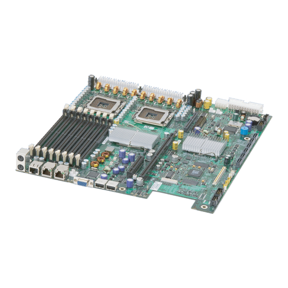
Server Board Features ® This chapter briefly describes the main features of the Intel Server Board S5000PAL. This chapter provides a photograph of the product, a list of the server board features, and diagrams showing the location of important components and connections on the server board. -
Page 17: Table 2. Server Board Features
Table 2. Server Board Features Feature Description ® ® Processor Support for up to two Dual-Core Intel Xeon processors 5000 sequence • Memory Eight DIMM slots supporting stacked DDR2 533/667 MHz FBDIMM memory •... -
Page 18: Connector And Component Locations
Connector and Component Locations V U S TP02071 NEXXUS4080AL User’s Guide... -
Page 19: Figure 2. Server Board Connector And Component Locations
Serial B Configuration Jumper System Fan 4 Header System Fan 3Header ® ® M. DIMM Sockets Intel 5000P MCH or Intel Processor 1 Socket 5000X MCH Processor 2 Socket Processor Fan 1 Header Voltage Regulator Heat Sink Processor Fan 2 Header... -
Page 20: Configuration Jumpers
Jumper Purpose BIOS Select If pins 1-2 are jumpered, the BIOS in the lower bank will be selected on the next reset. These pins should be jumpered on 2-3 for normal operation. Figure 3. BIOS Select Jumper NEXXUS4080AL User’s Guide... -
Page 21: Figure 4. Recovery Jumpers
These pins should be jumpered on 1-2 for normal operation. BMC Force Update Mode If pins 2-3 are jumpered, BMC Force Update Mode is enabled. These pins should be jumpered on 1-2 for normal operation. Figure 4. Recovery Jumpers NEXXUS4080AL User’s Guide... -
Page 22: Intel Light Guided Diagnostics
® Intel Light Guided Diagnostics The server board contains diagnostic LEDs to help you identify failed and failing components, and to help you identify the server from among several servers. Except for the ID LED, the status LED, and the 5V standby LED, the LEDs turn on (amber) only if a failure occurs. -
Page 23: Back Panel Connectors
Back Panel Connectors TP02081 Mouse Keyboard Serial Port B NIC 1 (10/100/1000 Mb) NIC 2 (10/100/1000 Mb) Video USB Port 6 USB Port 5 Figure 6. Back Panel Connectors NEXXUS4080AL User’s Guide... -
Page 24: Raid Support
To enable RAID 5, this activation key is placed on the SATA Key connector that ® is located at the left side of the server board. For information on how to install the Intel RAID Activation Key AXXRAKSW5 accessory to enable RAID 5, see the documentation that is included with the accessory kit. -
Page 25: Hardware Requirements
For a list of qualified components, see the links under "Additional Information and Software." Processor ® ® One or two Dual-Core Intel Xeon processors 5000 sequence. For a complete list of supported processors, see the links under "Additional Information and Software."... -
Page 26: Memory
For performance reasons, when configuring four DIMMs, DIMM pairs A2 and B2 should never be populated before DIMM pair C1 and D1. A four DIMM configuration should be populated as A1 and B1; C1 and D1. See Figure 8 for a four DIMM configuration example. NEXXUS4080AL User’s Guide... -
Page 27: Figure 8. Four Dimm Configuration Example
DIMMs installed. Since the data is duplicated across DIMMs, it means that up to one-half of the installed DIMMs are actively in use at any one time. The remaining DIMMs are used for mirroring. NEXXUS4080AL User’s Guide... -
Page 28: Power Supply
The Intel RAID Activation Key AXXRAKSW5 can be purchased and installed to enable ® RAID 5 support on your server board. An Intel RAID Activation Key can be installed in the SATA RAID 5 Key connector. Installation instructions for the RAID Activation Key are included with the accessory. -
Page 29: Chapter 3: Server Utilities
You can run BIOS Setup with or without an operating system ® being present. See “Additional Information and Software” for a link to the Intel 5000 Series Chipsets Server Board Family Datasheet where you will find details about specific BIOS setup screens. -
Page 30: Table 4. Setup Menu Key Use
If "No" is selected and the <Enter> key is pressed, or if the <Esc> key is pressed, the user is returned to where they were before <F9> was pressed without affecting any existing field values. NEXXUS4080AL User’s Guide... -
Page 31: Upgrading The Bios
Press <F2> Key if you want to run SETUP 2. Write down the current settings in the BIOS Setup program. Note: Do not skip step 2. You will need these settings to configure your computer at the end of the procedure. NEXXUS4080AL User’s Guide... -
Page 32: Upgrading The Bios
1. Power down the system and disconnect the AC power. 2. Open the server chassis. 3. Move the jumper from the normal operation position, Password Clear Protect, at pins 1 and 2 to the Password Clear Erase position, covering pins 2 and 3. NEXXUS4080AL User’s Guide... -
Page 33: Clearing The Cmos
1. Power down the system and disconnect the AC power. 2. Open the server. 3. Move the jumper from the normal operation position, CMOS Clear by BMC, at pins 1 and 2 to the CMOS Clear Force Erase position, covering pins 2 and 3. NEXXUS4080AL User’s Guide... -
Page 34: Figure 10. Clear Cmos Jumper
5. Return the CMOS Clear jumper to the CMOS Clear by BMC location, covering pins 1 and 2. 6. Close the server chassis. 7. Reconnect the AC power and power up the system. 8. The CMOS is now cleared and can be reset by going into the BIOS setup. NEXXUS4080AL User’s Guide... -
Page 35: Chapter 4: Hardware Installations And Upgrades
Hardware Installations and Upgrades Before You Begin Before working with your server product, pay close attention to the “Safety Information” at the beginning of this manual. Tools and Supplies Needed • Phillips* (cross head) screwdriver (#1 bit and #2 bit) •... -
Page 36: Figure 11. Installing The Memory
9. Insert the bottom edge of the DIMM into the socket. 10. When the DIMM is inserted, push down on the top edge of the DIMM until the retaining clips snap into place. Make sure the clips are firmly in place. NEXXUS4080AL User’s Guide... -
Page 37: Removing Dimms
(1) Touch the metal chassis before touching the processor or server board. Keep part of your body in contact with the metal chassis to dissipate the static charge while handling the processor. (2) Avoid moving around unnecessarily. NEXXUS4080AL User’s Guide... -
Page 38: Installing The Processor
TP02074 Figure 12. ILifting the Processor Socket Handle 6. Raise the CPU load plate (see Figure 13). TP02075 Figure 13. Installing the Processor Note: Do not touch the socket pins; they are very sensitive and easily damaged. NEXXUS4080AL User’s Guide... -
Page 39: Figure 14. Removing The Socket Cover
14). Note: Retain the protective socket cover for use when removing a processor that will not be replaced. TP02076 Figure 14. Removing the Socket Cover 9. Lower the CPU load plate and lower the socket lever completely. NEXXUS4080AL User’s Guide”... -
Page 40: Installing The Heat Sink(S)
4. Reinstall and reconnect any parts you removed or disconnected to reach the processor sockets. 5. Replace the server's cover and reconnect the AC power cord. See the documentation that came with your server chassis for instructions on installing the server's cover. NEXXUS4080AL User’s Guide... -
Page 41: Removing A Processor
9. Lift the processor lever. 10. Raise the CPU load plate. 11. Remove the processor. 12. If installing a replacement processor, see “Installing the Processor”. Otherwise, install the protective socket cover over the empty processor socket and reinstall the chassis cover. NEXXUS4080AL User’s Guide”... -
Page 42: Replacing The Backup Battery
Varning: Explosionsfara vid felaktigt batteribyte. Använd samma batterityp eller en ekvivalent typ som rekommenderas av apparattillverkaren. Kassera använt batteri enligt fabrikantens instruktion. Varoitus: Paristo voi räjähtää, jos se on virheellisesti asennettu. Vaihda paristo ainoastaan laitevalmistajan suosittelemaan tyyppiin. Hävitä käytetty paristo valmistajan ohjeiden mukaisesti. NEXXUS4080AL User’s Guide... -
Page 43: Figure 16. Replacing The Backup Battery
8. Remove the new lithium battery from its package, and, being careful to observe the correct polarity, insert it in the battery socket. 9. Close the chassis. 10. Run Setup to restore the configuration settings to the RTC. NEXXUS4080AL User’s Guide”... - Page 44 NEXXUS4080AL User’s Guide”...
-
Page 45: Appendix A: Getting Help
Appendix A: Getting Help World Wide Web http://www.vxtech.com/. Telephone U.S. and Canada 1-877-VXTECH8... - Page 46 NEXXUS4080AL User’s Guide...
-
Page 47: Appendix B: Regulatory And Compliance Information
Product EMC Compliance - Class A Compliance Note: Legally this product is required to comply with Class A emission requirements as it is intended for a commercial type market place. Intel targets 10db margin to Class A Limits. ® The Intel... -
Page 48: Certifications / Registrations / Declarations
This product is provided with the following Product Certification Markings: Table 5. Product Certification Markings Regulatory Region Marking Compliance UL Mark USA/Canada CE Mark Europe FCC Marking (Class A) EMC Marking (Class Canada CANADA ICES-003 CLASS A CANADA NMB-003 CLASSE A NEXXUS4080AL User’s Guide... -
Page 49: Electromagnetic Compatibility Notices
• Reorient or relocate the receiving antenna. NEXXUS4080AL User’s Guide... -
Page 50: Industry Canada (Ices-003)
Directive (73/23/EEC) and EMC Directive (89/336/EEC). The product has been marked with the CE Mark to illustrate its compliance. Taiwan Declaration of Conformity (BSMI) The BSMI Certification Marking and EMC warning is located on the outside rear area of the product. NEXXUS4080AL User’s Guide... -
Page 51: Korean Compliance (Rrl)
Korean Compliance (RRL) English translation of the notice above: 1. Type of Equipment (Model Name): On License and Product 2. Certification No.: On RRL certificate. Obtain certificate from local Intel representative 3. Name of Certification Recipient: Intel Corporation 4. Date of Manufacturer: Refer to date code on product 5. -
Page 52: Restriction Of Hazardous Substances (Rohs) Compliance
Restriction of Hazardous Substances (RoHS) Compliance Intel has a system in place to restrict the use of banned substances in accordance with the European Directive 2002/95/EC. Compliance is based on declaration that materials banned in the RoHS Directive are either (1) below all applicable substance threshold limits or (2) an approved/pending RoHS exemption applies. -
Page 53: Appendix C: Troubleshooting
In addition to the server firmware and files, also update any drivers used for components you have installed in your system, such as video drivers, network drivers, and SATA drivers. Intel provides a package called the "Platform Confidence Test" that may help with your diagnostics. See “Additional Information and Software”... -
Page 54: Problems Following Initial System Installation
• Are all integrated components from the tested components lists? Check the tested memory, and chassis lists, as well as the supported hardware and operating system list. See “Additional Information and Software” for links to the tested component lists. NEXXUS4080AL User’s Guide... -
Page 55: Hardware Diagnostic Testing
Confirming Loading of the Operating System Once the system boots up, the operating system prompt appears on the screen. The prompt varies according to the operating system. If the operating system prompt does not appear, “No Characters Appear on Screen”. NEXXUS4080AL User’s Guide... -
Page 56: Specific Problems And Corrective Actions
• Remove the processor(s) and re-seat them. • Make sure the chassis standoffs are installed only below mounting holes. Misplaced standoffs can contact the pins on the bottom of the server board and cause a short. NEXXUS4080AL User’s Guide... -
Page 57: No Characters Appear On Screen
Characters Are Distorted or Incorrect Check the following: • Are the brightness and contrast controls properly adjusted on the video monitor? See the manufacturer's documentation. • Are the video monitor's signal and power cables properly installed? NEXXUS4080AL User’s Guide... -
Page 58: System Cooling Fans Do Not Rotate Properly
CD-ROM Drive or DVD-ROM Drive Activity Light Does Not Light Check the following: • Are the CD-ROM/DVD-ROM drive's power and signal cables properly installed? • Are all relevant switches and jumpers on the drive set correctly? • Is the drive properly configured? NEXXUS4080AL User’s Guide... -
Page 59: Problems With Network
Make sure the other adapter supports shared interrupts. Make sure your operating system supports shared interrupts. • Try reseating the add-in adapter. The add-in adapter stopped working without apparent cause • Reseat the adater. • Put the adapter in a different slot. NEXXUS4080AL User’s Guide... -
Page 60: System Boots When Installing Pci Card
• If you are running the software from a CD-ROM or DVD-ROM, try a different disk. • Check your system for a virus infection. • Uninstall and reinstall the software. Make sure all necessary files are installed. NEXXUS4080AL User’s Guide... -
Page 61: Devices Are Not Recognized Under Device Manager (Microsoft* Windows* Operating System)
• If using a RAID configuration with SCSI or SATA drives, make sure the RAID card is installed correctly. Bootable CD-ROM Disk Is Not Detected Check the following: • Make sure the BIOS is configured to allow the CD-ROM to be the first bootable device. NEXXUS4080AL User’s Guide... -
Page 62: Led Information
Replace or reseat the system video add-in card. If on-board video is bing used, the server board may be faulty. NEXXUS4080AL User’s Guide... -
Page 63: Table 9. Error Beep Codes Generated By Intel
® In addition to the beep codes above, additional beep codes are provided if an Intel ® Remote Management Module is installed. The Intel Remote Management Module provides the following additional beep codes. ® Table 9. Error Beep Codes Generated by Intel... - Page 64 NEXXUS4080AL User’s Guide...
-
Page 65: Appendix D: Led Decoder
Appendix D: LED Decoder During the system boot process, BIOS executes a number of platform configuration processes, each of which is assigned a specific hex POST code number. As each configuration routine is started, BIOS will display the given POST code to the POST Code Diagnostic LEDs found on the back edge of the server board. -
Page 66: Table 11. Diagnostic Led Post Code Decoder
DIMM) 0x23h Detecting presence of memory 0x24h Programming timing parameters in the memory controller 0x25h Configuring memory parameters in the memory controller 0x26h Optimizing memory controller settings 0x27h Initializing memory, such as ECC init 0x28h Testing memory NEXXUS4080AL User’s Guide... - Page 67 Enabling the video controller (VGA) Remote Console 0x78h Resetting the console controller 0x79h Disabling the console controller 0x7Ah Enabling the console controller Keyboard (PS2 or USB) 0x90h Resetting the keyboard 0x91h Disabling the keyboard 0x92h Detecting the presence of the keyboard NEXXUS4080AL User’s Guide...
- Page 68 Trying boot device selection 0xD3 Trying boot device selection 0xD4 Trying boot device selection 0xD5 Trying boot device selection 0xD6 Trying boot device selection 0xD7 Trying boot device selection 0xD8 Trying boot device selection 0xD9 Trying boot device selection NEXXUS4080AL User’s Guide...
- Page 69 Entering Sleep state 0xF5h Exiting Sleep state 0xF8h Operating system has requested EFI to close boot services (ExitBootServices ( ) has been called) 0xF9h Operating system has switched to virtual address mode (SetVirtualAddressMap ( ) has been called) NEXXUS4080AL User’s Guide...
- Page 70 Crisis recovery has been initiated because of a user request 0x31h Crisis recovery has been initiated by software (corrupt flash) 0x34h Loading crisis recovery capsule 0x35h Handing off control to the crisis recovery capsule 0x3Fh Unable to complete crisis recovery. NEXXUS4080AL User’s Guide...
Need help?
Do you have a question about the NEXXUS4080AL and is the answer not in the manual?
Questions and answers