H3C S12500R Series Installation, Quick Start
Ethernet switch router
Hide thumbs
Also See for S12500R Series:
- Installation manual (102 pages) ,
- Hardware reference manual (69 pages) ,
- Configuration examples (19 pages)

Related Manuals for H3C S12500R Series


Summary of Contents for H3C S12500R Series
- Page 1 H3C S12500R Ethernet Switch Router Series Installation Quick Start New H3C Technologies Co., Ltd. http://www.h3c.com Document version: 5PW101-20200426...
- Page 2 The information in this document is subject to change without notice. All contents in this document, including statements, information, and recommendations, are believed to be accurate, but they are presented without warranty of any kind, express or implied. H3C shall not be liable for technical or editorial errors or omissions contained herein.
-
Page 3: Table Of Contents
Contents 1 Preparing for installation ······························································· 1-1 ESD prevention ······················································································································ 1-1 Examining the installation site ···································································································· 1-1 Installation tools and equipment ································································································· 1-2 2 Installing the device ····································································· 2-1 Device dimensions ·················································································································· 2-1 Rack requirements ·················································································································· 2-3 ... -
Page 4: Preparing For Installation
EMI, grounding, power supply, ventilation, and space requirements. As a best practice, reserve a minimum clearance of 1.2 m (3.94 ft) between the device and walls or other devices. For more information about the installation site requirements, see H3C S12500R Switch Router Series Installation Guide. -
Page 5: Installation Tools And Equipment
Installation tools and equipment No installation tools and equipment are provided with the device. Prepare them yourself as required. -
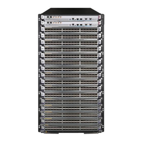
Page 6: Installing The Device
Installing the device Device dimensions Figure 2-1 S12516R dimensions (1) Fan tray handle (2) Mounting bracket (3) Cable management bracket... - Page 7 Figure 2-2 S12508R dimensions (1) Fan tray handle (2) Mounting bracket (3) Cable management bracket Figure 2-3 S12504R dimensions (with the LSXM104XFAN fan trays) (1) Fan tray handle (2) Mounting bracket (3) Cable management bracket Figure 2-4 S12504R dimensions (with the LSXM104XFANH fan trays) (1) Fan tray handle (2) Mounting bracket (3) Cable management bracket...
-
Page 8: Rack Requirements
Rack requirements Table 2-1 Device dimensions and rack requirements Model Device dimensions Rack requirements • Height—931 mm (36.65 in) (21 RU) • Width—440 mm (17.32 in) • Total depth—977 mm (38.46 in) 857 mm (33.74 in) for the chassis 102 mm (4.02 in) from the rear side of S12516R the mounting bracket front ear to the management bracket front end... -
Page 9: Slide Rail Requirements
Slide rail requirements IMPORTANT: The device is heavy. Install the device at the lowest possible position. Attach the required slide rails to the rack before you mount the device in the rack. For more information about attaching slide rails, see the installation guide for the slide rails. Before attaching the slide rails, read signs on the slide rails to identify the right and left slide rails and their front and rear ends. - Page 10 Figure 2-5 Installing cage nuts (S12516R)
- Page 11 Figure 2-6 Installing cage nuts (S12508R) Figure 2-7 Installing cage nuts (S12504R)
-
Page 12: Mounting The Device In A Rack
Mounting the device in a rack WARNING! To avoid device damage or bodily injury, follow these guidelines to lift and move the device: • The device is heavy. As a best practice, use a forklift to lift and move the device. •... -
Page 13: Grounding The Device
Figure 2-8 Mounting the device in the rack (S12516R) (1) Chassis handle (2) Slide the chassis into the rack (3) Use screws to secure the mounting brackets to the rack Grounding the device CAUTION: • Grounding the device reliably is crucial to lightning protection and EMI protection. Ground the device reliably before you use it. - Page 14 Figure 2-9 Connecting the grounding cable to a grounding strip (S12516R) (1) Use the grounding screws to attach the two-hole grounding lug to the grounding point (2) Grounding sign (3) Grounding strip (4) Grounding post (5) Ring terminal (6) Hex nut...
-
Page 15: Installing Frus
This section describes the installation procedures for the MPUs, service modules, fabric modules, fan trays, and power modules. For the compatibility matrix between these modules and the device models, see H3C S12500R Switch Router Series Installation Guide. WARNING! Long-time exposure to strong air flow might cause discomfort. As a best practice, do not stand close to the air outlet vents while the device is operating. -
Page 16: Installing Mpus For The S12504R
As shown by callout 4 in Figure 3-1, continue to push the MPU by its middle part on the front panel until you cannot move it. As shown by callout 5 in Figure 3-1, push the ejector levers inward until they come in close contact with the front panel. -
Page 17: Installing Service Modules
Figure 3-2 Installing an MPU (S12504R) (1) Loosen the captive screws and remove the filler panel (2) Pivot up the handle (3) Push the MPU into the slot along the guide rails (4) Push the MPU until the handle makes close contact with the slot edges (5) Push the handle until the MPU is secure in position (6) Fasten the screws on the MPU Installing service modules... - Page 18 Installing service modules CAUTION: Install filler panels in the empty service module slots. The service module ejector levers and the ejector lever seats on the service module slots have purple marks. To install a service module: Remove the filler panel from the target service module slot. The filler panel removal procedure is the same for service module and MPU slots.
-
Page 19: Installing Cable Management Brackets
Figure 3-3 Installing a service module (S12516R) (1) Push the service module slowly along the guide rails into the slot (2) Pull the ejector levers outward (3) Push the service module by the middle part on the front panel (4) Pull the ejector levers inward (5) Fasten the captive screws on the service module Installing cable management brackets The cable management brackets are installed on the two sides of the service module slots. -
Page 20: Installing Fabric Modules
Figure 3-4 Installing a cable management bracket (S12516R) (1) Spring tab on the cable management bracket (2) Align the cable management bracket with the bracket hole NOTE: You must press the spring tab while you are removing a cable management bracket. Installing fabric modules WARNING! When you hot swap a fabric module, only one fan tray is operating and it automatically increases... - Page 21 To install a fabric module: Place the fabric module on a workbench and remove the protection box from the connector side of the fabric module. See Figure 3-5. Release the ejector levers by pressing the spring clips. Orient the fabric module with the side marked "Up" facing up. Hold the fabric module front panel near the ejector levers with one hand and support the module bottom with the other.
-
Page 22: Installing A Filler Panel In A Fabric Module Slot
Figure 3-6 Installing a fabric module (S12516R) (1) Push the fabric module slowly into the slot (2) Rotate the ejector levers inward until the spring clips lock the ejector levers in place Installing a filler panel in a fabric module slot The device comes with empty fabric module slots. -
Page 23: Removing A Filler Panel From A Fabric Module Slot
Figure 3-7 Installing a filler panel in a fabric module slot (S12516R) (1) Push the filler panel slowly into the slot (2) Simultaneously rotate the ejector levers inward (3) Fasten the captive screws on the ejector levers Removing a filler panel from a fabric module slot As shown by callout 1 in Figure 3-8, loosen the captive screws on the ejector levers. -
Page 24: Installing Fan Trays
Figure 3-8 Removing the filler panel from a fabric module slot (S12516R) (1) Loosen the captive screws on the ejector levers (2) Rotate the ejector levers outward (3) Pull the filler panel out of the slot along the guide rails Installing fan trays WARNING! •... -
Page 25: Installing Fan Trays For The S12516R Or S12508R
Installing fan trays for the S12516R or S12508R WARNING! The fan tray is high and heavy. To avoid device damage or bodily injury, use two people to install or remove a fan tray. To install a fan tray for the S12516R or S12508R: Orient the fan tray with the lettering on it facing upward and align the fan tray with the fan tray slot. -
Page 26: Installing Fan Trays For The S12504R
Installing fan trays for the S12504R Orient the fan tray correctly. To install a fan tray in the FAN1 slot, orient the fan tray so that the LEDs are on the left side of the front panel. To install a fan tray in the FAN2 slot, orient the fan tray so that the LEDs are on the right side of the front panel. -
Page 27: Connecting The Power Cord
Figure 3-11 Removing a filler panel Figure 3-12 Installing a power module (S12516R) Connecting the power cord WARNING! • Make sure a circuit breaker is provided for each power input line. • Before you connect a power cord, make sure the circuit breaker for it is turned off. CAUTION: Before powering on the device, make sure the fan trays are installed correctly. -
Page 28: Connecting A Dc Power Cord
Figure 3-13 Using a releasable cable tie to secure the power cord to the device (S12516R) Connecting a DC power cord Connect the DC power cord connector to the DC-input receptacle on the power module. Fasten the screw on the connector to secure the DC power cord in place. Connect the other end of the DC power cord to a DC power source. -
Page 29: (Optional) Installing Transceiver Modules
(Optional) Installing transceiver modules CAUTION: • If you are not to install a transceiver module or cable in an SFP+ port, keep the dust plug in the port, to prevent particles from entering the port. • If you are not to install a transceiver module or cable in a QSFP28 port, install a dust plug that comes with the service module in the QSFP28 port, to prevent particles from entering the port. -
Page 30: Connecting An Sfp+/Qsfp+/Qsfp28/Qsfp+ To Sfp+ Dac Cable
Connecting an SFP+/QSFP+/QSFP28/QSFP+ to SFP+ DAC cable CAUTION: When you connect a fiber cable, make sure the bend radius of the cable is no less than eight times the fiber diameter. The cables are hot swappable. Use SFP+ DAC cables to connect SFP+ ports, QSFP+ DAC cables to connect QSFP+ ports, QSFP28 DAC cables to connect QSFP28 ports, and QSFP+ to SFP+ DAC cables to connect QSFP+ and SFP+ ports. -
Page 31: Cabling Recommendations
Cabling recommendations Routing network cables The cable management brackets are attached to the chassis front edges on its two sides. As a best practice, route the cables from the left half of the chassis through the left cable management bracket and the cables from the right half of the chassis through the right cable management bracket, as shown in Figure 4-1. -
Page 32: Accessing The Device
Accessing the device The first time you access the device you must use a console cable to connect a console terminal, for example, a PC, to the console port on the device. Connecting the console cable IMPORTANT: • Identify the mark on the console port and make sure you are connecting to the correct port. •... -
Page 33: Iewing Device Startup Information
The cooling system is working, and you can hear fan rotating noise and feel air being blown out. The LEDs on the MPUs show that the system is operating correctly. For more information • about LEDs, see H3C S12500R Switch Router Series Hardware Reference.
Need help?
Do you have a question about the S12500R Series and is the answer not in the manual?
Questions and answers