H3C S12500R Series Hardware Reference Manual
Switch router
Hide thumbs
Also See for S12500R Series:
- Installation manual (102 pages) ,
- Hardware reference manual (42 pages) ,
- Installation, quick start (33 pages)

Related Manuals for H3C S12500R Series


Summary of Contents for H3C S12500R Series
- Page 1 H3C S12500R Switch Router Series Hardware Reference New H3C Technologies Co., Ltd. http://www.h3c.com Document version: 6W104-20221025...
- Page 2 The information in this document is subject to change without notice. All contents in this document, including statements, information, and recommendations, are believed to be accurate, but they are presented without warranty of any kind, express or implied. H3C shall not be liable for technical or editorial errors or omissions contained herein.
- Page 3 Preface This document describes the hardware information for the H3C S12500R switch routers, including chassis views and technical specifications, FRUs and compatibility matrixes, LEDs, and cables. This preface includes the following topics about the documentation: • Audience. • Conventions. •...
- Page 4 Symbols Convention Description An alert that calls attention to important information that if not understood or followed WARNING! can result in personal injury. An alert that calls attention to important information that if not understood or followed CAUTION: can result in data loss, data corruption, or damage to hardware or software. An alert that calls attention to essential information.
- Page 5 Documentation feedback You can e-mail your comments about product documentation to info@h3c.com. We appreciate your comments.
-
Page 6: Table Of Contents
Contents 1 Chassis views and technical specifications ·············································· 1-1 Chassis views ················································································································································· 1-1 Chassis components ······································································································································· 1-4 Technical specifications ································································································································ 1-10 Weights and dimensions ······················································································································· 1-10 Module power consumption and system power consumption······························································· 1-14 Heat dissipation ····································································································································· 1-17 Environmental specifications ················································································································· 1-17 Chassis ordering information ························································································································... -
Page 7: Chassis Views And Technical Specifications
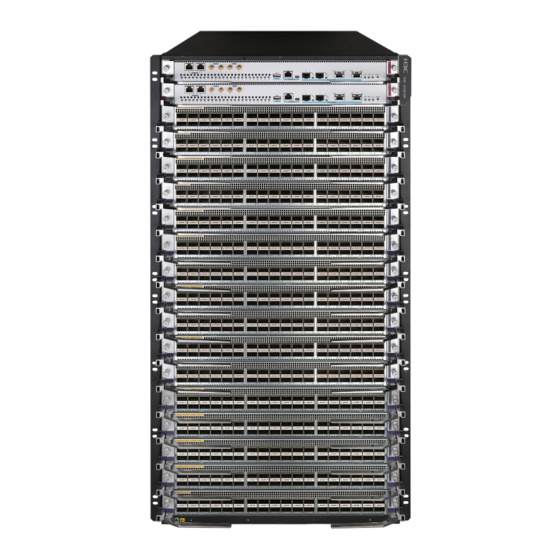
Chassis views and technical specifications The H3C S12500R Ethernet Switch Router Series is a set of next-generation rack switch routers designed for data center core networks. It optimizes the CLOS switching fabric architecture and uses the variable cell-based traffic scheduling and control forwarding mechanism to deliver higher forwarding efficiency, more refined congestion control, and hierarchical scheduling. - Page 8 Figure 1-2 S12508R Figure 1-3 S12504R...
- Page 9 Figure 1-4 S12516CR Figure 1-5 S12508CR...
-
Page 10: Chassis Components
Figure 1-6 S12500R-2XL Figure 1-7 S12500R-2L Chassis components The device has a service module section, power module section, fan tray section, fabric module section, MPU section, and environment management module section. The S12500R-2XL and S12500R-2L use built-in fabric modules and do not have a fabric module section. Only the S12508CR and S12516CR have environment management module sections. - Page 11 Figure 1-8 Front and rear views of the S12500R-2L (1) SEU section (2) Interface module section (3) Power supply section (4) Fan tray section Table 1-1 Section descriptions for the S12500R-2L Section Description No SEUs are provided with the device. Purchase SEUs SEU section yourself.
- Page 12 Figure 1-9 Front and rear views of the S12516R (1) MPU section (2) Service module section (3) Power module section (4) Fan tray section (5) Fabric module section Table 1-2 Section description for the S12516R Section Description MPU section • (S12516R and S12508R—Ejector levers No MPUs are provided with the device.
- Page 13 Section Description No power modules are provided with the device. Purchase power modules yourself. • S12516R—16 power module slots, with eight on each side of the chassis rear. • S12508R—8 power module slots, with four on each side of the chassis rear. •...
- Page 14 Figure 1-10 Front and rear views of the S12516CR Table 1-3 Section description for the S12516CR Section Description No power trays or power supplies are provided with the device. Purchase power trays and power supplies yourself. • S12516CR—Six power tray slots. Each power tray has six power supply slots.
- Page 15 Section Description the device, you can install it in either of the MPU slots. No interface modules are provided with the device. Purchase interface modules yourself. Interface module section • S12516CR—16 interface module slots. (The edges or ejector levers of the interface •...
-
Page 16: Technical Specifications
Environ ment Service Power Power Model manage Fabric module module module tray tray ment module are covered by tray FAN 2. provide • s six Slots 24 and 25 power are covered by supply FAN 3. slots • Slots 26 and 27 PWR 1 are covered by to PWR... - Page 17 Model Weight Height Width Depth 111.6 kg (246.03 1331 mm (52.40 in)/30 S12516CR 442 mm (17.40 in) 920 mm (36.22 in) S12508CR 82.4 kg (181.66 lb) 842 mm (33.15 in)/19 RU 442 mm (17.40 in) 920 mm (36.22 in) S12500R-2L 22.6 kg (49.82 lb) 133 mm (5.24 in)/3 RU 440 mm (17.32 in)
- Page 18 Model Weight Height Width Depth LSXM1CDMS36KC 11.8 kg (26.01 50.0 mm (1.97 in) 446.4 mm (17.57 in) 519.8 mm (20.46 in) LSXM1CDQ24KBR 10.0 kg (22.05 50.0 mm (1.97 in) 432.6 mm (17.03 in) 519.8 mm (20.46 in) LSXM1CDQ36KBR 13.1 kg (28.88 50.0 mm (1.97 in) 446.4 mm (17.57 in) 519.8 mm (20.46 in)
- Page 19 NOTE: Module dimensions are expressed as follows: • Height—Height of the front panel of the module. • Width—Width of the front panel of the module. • Depth—Depth from the front panel of the module to the connector (Including the connector, but excluding the ejector levers and captive screws).
-
Page 20: Module Power Consumption And System Power Consumption
Table 1-10 Power module weights and dimensions Model Weight Height Width Depth PSR1800-56A 1.6 kg (3.53 lb) 40.1 mm (1.58 in) 82.6 mm (3.25 in) 297.7 mm (11.72 in) PSR1800-56D 2.0 kg (4.41 lb) 40.1 mm (1.58 in) 82.6 mm (3.25 in) 297.7 mm (11.72 in) PSR2400-54A 1.9 kg (4.19 lb) - Page 21 • The static power consumption of a module refers to the power consumed by the module when module is running but all ports on the module are down and when no transceiver module is available on the optical interface of the module. •...
- Page 22 Minimum static Typical power Maximum dynamic Model power consumption consumption power consumption LSXM1CGQ72KCR1 530 W 635 W 980 W LSXM1TGS48HFR1 136 W 161 W 230 W LSXM1CGQ18QGHFR1 316 W 425 W 650 W LSXM1CGQ6QGHFR1 132 W 171 W 325 W LSXM1TGS48HBR1 111 W 127 W...
-
Page 23: Heat Dissipation
Fan tray Minimum power Typical power Maximum power Device model model consumption consumption consumption LSXM108XFAN 17 W 103 W 395 W S12508R LSXM108XFAN 86 W 317 W 1239 W S12504R LSXM104XFAN 14 W 66 W 255 W LSXM104XFAN S12504R 19.4 W 87 W 588 W LSXM104XFAN... -
Page 24: Chassis Ordering Information
Chassis ordering information To purchase an S12500R chassis, contact the sales agent or H3C sales personnel. Table 1-16 S12500R chassis ordering information Product code Product name Description 0235A2FL S12516R H3C S12516R Ethernet switch router chassis 0235A2FN S12508R H3C S12508R Ethernet switch router chassis... - Page 25 Contents 2 FRUs and compatibility matrixes ······························································ 2-1 FRUs compatibility ·········································································································································· 2-1 S12500R ················································································································································· 2-1 S12500CR ··············································································································································· 2-1 MPUs ······························································································································································ 2-2 Environment management module ················································································································· 2-4 Interface module adapter ································································································································ 2-5 Service modules·············································································································································· 2-5 Interface modules············································································································································ 2-8 Fabric modules················································································································································ 2-8 Fabric module slot filler panels························································································································...
-
Page 26: Frus And Compatibility Matrixes
FRUs and compatibility matrixes FRUs compatibility S12500R Table 2-1 S12500R modules compatibility Device model Fabric module Service module • LSXM2SFH16CR1 • LSXM1SFH16ER1 S12516R • LSXM1SFK16ER1 • LSXM1SFK16GR1 LSXM1SUPER1 Type H service modules • LSXM1SUPEAR1 LSXM1SFH08CR1 (LSXM1TGS48HFR1 for • LSXM1SFH08DR1 example) and Type K S12508R •... -
Page 27: Mpus
Environment Device model management Fabric module Service module module • Table 2-10. LSXM1SFK0 8FR1 • LSXM1SFK0 8GR1 Table 2-3 S12500CR Type S modules compatibility Environment Device model management Fabric module Service module module • LSXM3SFS1 Type S service S12516CR • LSXM3SFS1 modules (LSXM3TGS48SF... - Page 28 LSXM1SUPKR1 LSXM1SUPER1 Item LSXM1SUP04TR1 LSXM1SUPKAR1 LSXM1SUPEAR1 LSXM1SUPRS2 Flash 4GB EMMC 8GB EMMC 4GB EMMC NVRAM 512 KB • • RJ-45 RJ-45 • RJ-45 • • • Port connector type • • USB (Type A) USB (Type A) • USB (Type A) •...
-
Page 29: Environment Management Module
Item LSXM1SUP02LR1 LSXM1SUP02TR1 • Coaxial RF connector • One console port • One 10/100/1000BASE-T port for • management and upgrade One console port • • One Gigabit SFP port for One 10/100/1000BASE-T port for management and upgrade management and upgrade Ports •... -
Page 30: Interface Module Adapter
For the transceiver modules or cables available for modules, see H3C S12500R Switch Series Cards and Transceiver Modules Compatibility Matrixes and H3C S12500R Switch Router Series Port Splitting and Compatibility With Transceivers and Cables. - Page 31 Service Service Compatible device Description Port quantity module module models type model 36-port 400G • S12516CR LSXM1CDQ36 QSFP-DD Ethernet • KBR1 optical interface S12508CR module • S12516R • 48-port 200G S12508R LSXM1CCQ48 QSFP56 Ethernet • S12504R KBR1 optical interface • S12516CR module •...
- Page 32 Service Service Compatible device module module Description Port quantity models type model • module S12504R 18-port 100G QSFP28 Ethernet • S12516R optical LSXM1CGQ1 • S12508R interface/36-port 40G 8QGHBR1 • QSFP+ Ethernet S12504R optical interface module 18-port 100G QSFP28 Ethernet • S12516R optical LSXM1CGQ1...
-
Page 33: Interface Modules
Service Service Compatible device Description Port quantity module module models type model interface module Interface modules The LSXM1MOD24KBR1 supports installation of interface modules. Table 2-11 describes the interface modules available for the LSXM1MOD24KBR1. Table 2-11 Interface modules available for the LSXM1MOD24KBR1 Model Description Port quantity and type... -
Page 34: Fabric Module Slot Filler Panels
NOTE: You can install a maximum of six Type S fabric modules (LSXM3SFS08F2 for example) on an S12516CR or S12508CR. For an S12508CR, install Type S fabric modules in slots 14 to 19. For an S12516CR, install Type S fabric modules in slots 22 to 27. Fabric module slot filler panels The device comes with empty fabric module slots. -
Page 35: Power Trays And Power Modules
Power trays and power modules CAUTION: You must install power modules of the same model for the device. The device supports N+N (dual power input lines) or N+1 (single power input line) power module redundancy. Determine the number of power modules based on the power supply mode and system power consumption. - Page 36 Item Specifications Maximum input current 16 A Maximum output current 55.6 A • 1200 W @ 100 to 175 VAC Maximum output power • 3000 W @ 175 to 240 VAC Dimensions (H × W × D) 41 × 100 × 332 mm (1.61 × 3.94 × 13.07 in) Operating temperature –10°C to +50°C (–14°F to +122°F) Ambient temperature...
- Page 37 Item PSR2000B-54D PSR3000B-54AHD • 240 VDC • 336 VDC • 90 to 150 VAC @ 47 to 63 Hz • 176 to 290 VAC @ 47 to 63 Hz Input voltage range –39 to –72 VDC • 180 to 290 VDC •...
-
Page 38: Fan Trays
Table 2-2 PSR1800-56D power supply specifications Item Specifications Rated input voltage –48 to –60 VDC Rated output voltage 56 VDC Maximum input current 45 A Maximum output current 32.2 A Maximum output power 1800 W Dimensions (H × W × D) 40.1 ×... -
Page 39: Dc Power Cords
Select 16A AC power cords for the device. For the connector types of different countries or regions, see http://www.h3c.com/en/Support/Resource_Center/EN/Home/Switches/00-Public/Install/Install ation_Guides/H3C_Power_Cords_Cables_UG-6W100/. Chassis component ordering information To purchase chassis components, contact the sales agent or H3C sales personnel. Table 2-5 Chassis component ordering information Product code Product name Description... - Page 40 0231AJC0 LSXM1CMURS2 H3C S12500CR switch environment management module Fabric modules 0231AD26 LSXM2SFH16CR1 H3C S12516R fabric module, Type H (Class C) 0231AD2A LSXM1SFH16ER1 H3C S12516R fabric module, Type H (Class E) 0231AD28 LSXM1SFH08CR1 H3C S12508R fabric module, Type H (Class C)
- Page 41 (QSFP-DD)(KC) H3C S12500R 36-port 200GBASE Ethernet optical interface 0231AGX6 LSXM1CGQ72KCR1 (QSFP56)/72-port 100GBASE Ethernet optical interface module (QSFP28)(KC) H3C S12500 16-port 400G Ethernet optical interface module 0231AGJ5 LSXM3CDQ16SF2 (QSFP-DD)(SF) H3C S12500 8-port 400G Ethernet optical interface module 0231AGJ6...
- Page 42 Fan module for the H3C S12508R 0231A2X9 LSXM104XFAN Fan module for the H3C S12504R 0231A4WX LSXM116XFANH High speed fan module for the H3C S12516R 0231A4X0 LSXM108XFANH High speed fan module for the H3C S12508R 0231A4X1 LSXM104XFANH High speed fan module for the H3C S12504R...
- Page 43 0231A3RM LSXM1BFP04A 04 fabric blank filler panel Slide rails 0231A4EK LSXM1BSR 1U bottom-support rails, 630mm-900mm 0231A0PL LSTM2KSGD0 Slide rail accessories, 500mm-800mm 0231A2VL LSVM1BSR10 H3C S9810 bottom support rails, 630mm-900mm Interface module adapter 0231AE4C LSXM1IMAA H3C S12500CR interface module adapter 2-18...
- Page 44 Contents 3 LEDs ········································································································ 3-1 MPU LEDs ······················································································································································ 3-1 Management Ethernet port LEDs············································································································ 3-2 Fan tray status LEDs ······························································································································· 3-2 Power module status LEDs ····················································································································· 3-3 Module status LEDs ································································································································ 3-3 MPU active/standby status LED ·············································································································· 3-3 Environment management module LEDs ······································································································· 3-4 Fan tray status LEDs ·······························································································································...
-
Page 45: Leds
LEDs The device components provide various LEDs to indicate the component operating status. Table 3-1 LEDs at a glance LEDs LEDs: • Management Ethernet port LEDs • Fan tray status LEDs • Power module status LEDs • Module status LEDs •... -
Page 46: Management Ethernet Port Leds
(1) 10/100/1000BASE-T management Ethernet port LED (LINK) (3) MPU active/standby status LED (ACT) (4) Power module status LED (PWR) (5) Fan tray status LED (FAN) (6) SFP management Ethernet port LED (LINK/ACT) (7) Module status LED (SLOT) Management Ethernet port LEDs 10/100/1000BASE-T management Ethernet port LEDs Each 10/100/1000BASE-T management Ethernet port has a pair of LEDs (LINK and ACT) or a single LED to indicate its operating status. -
Page 47: Power Module Status Leds
Power module status LEDs An MPU provides one power module status LED to indicate the status of the power modules. For the description of the LED, see Table 3-5. Table 3-5 Power module status LED description for MPUs Status Description Steady green All power modules are operating correctly. -
Page 48: Environment Management Module Leds
Environment management module LEDs The following figure uses the LSXM1CMUR1 environment management module for illustration. Figure 3-2 LSXM1CMUR1 environment management module LEDs (1) Fan tray status LED (FAN) (2) Operating status LED (RUN/ALM) (3) ETH management port status LED (LINK/ACT0) (4) ETH management port status LED (LINK/ACT1) (6) Active/standby status LED for the environment (5) Power module status LED (PWR) -
Page 49: Operating Status Leds
Operating status LEDs An environment management module provides one operating status LED to indicate the operating status of the environment management module. For the description of the LED, see Table 3-10. Table 3-10 Operating status LED description Status Description Flashing green The environment management module is operating correctly. -
Page 50: Sfp Port Leds
SFP port LEDs A LED is provided for each SFP port to indicate the link status and data receiving/transmitting status of the SFP ports. Table 3-13 SFP port LED description LED status Description Flashing The SFP port is receiving or sending data. Green A link is present. -
Page 51: Qsfp28 Port Leds
QSFP+ port LED status Description No link is present. Flashing A minimum of one channel is receiving or sending data. Split into four 10G A link is present on a minimum of one channel. channels No link is present. QSFP28 port LEDs A LED is provided for each QSFP28 port to indicate the link status and data receiving/transmitting status of the QSFP28 ports. -
Page 52: Fabric Module Status Leds On A Fan Tray
Table 3-19 Description for the fabric module status LED on a fabric module LED status Description Green The fabric module is operating correctly. The fabric module has failed or is loading software. No power is provided to the fabric module or the fabric module has not started loading software. -
Page 53: Fan Tray Leds
(1) LEDs for the fabric module slot 6 (2) LEDs for the fabric module slot 8 (5) LEDs for the fabric module slot 11 (6) Fabric module slot number Table 3-20 Description for fabric module status LEDs on an S12516R/S12508R/S12504R fan tray Description Flashing (once per... - Page 54 Status Description input voltage. Green Power is being input correctly. Green Power is being output correctly. The power module is in self-protection state because of one of the following problems: • Output short-circuit. • Output overcurrent. • Output overvoltage. • Input under-voltage.
- Page 55 Status Description No power input. Green Power is being output correctly. Output overvoltage, output overcurrent, or overtemperature protection state. PSR1800-56A Green Normal power input. Abnormal or no power input. Green Normal power output. Abnormal power output. No power output. PSR1800-56D Green Normal power input.
- Page 56 Contents 4 Cables ····································································································· 4-1 Console cable ················································································································································· 4-1 Connecting a DB9-to-RJ45 console cable ······························································································ 4-2 Connecting a USB-to-RJ45 console cable ······························································································ 4-3 Ethernet twisted pair cable ······························································································································ 4-5 RJ-45 connector ······································································································································ 4-5 Cable pinouts ·········································································································································· 4-5 Cable type ··············································································································································· 4-5 Pin assignments ······································································································································...
-
Page 57: Cables
USB-to-RJ45 console USB connector RJ-45 connector cable The signal pinout for the RJ-45 connector of a serial console cable varies by vendor. To avoid abnormal configuration terminal display, use a serial console cable provided by H3C. For more... -
Page 58: Connecting A Db9-To-Rj45 Console Cable
RJ-45 connector is the same as that shown in Table 4-3. Table 4-2 Console cable views Product code for the Console cable type Console cable view recommended H3C console cable DB9-to-RJ45 console cable 04042967 USB-to-RJ45 console cable 0404A1EE Connecting a DB9-to-RJ45 console cable... -
Page 59: Connecting A Usb-To-Rj45 Console Cable
Click the following link, or copy it to the address bar on your browser and download the USB-to-RJ45 console driver. http://www.h3c.com/en/home/USB_to_RJ45_Console/ View the TXT file Read me in the Windows folder to check whether the Windows system of the configuration terminal supports the driver. - Page 60 Figure 4-2 Driver installation wizard Click Finish after the drive installation is completed. Figure 4-3 Finishing the driver installation Connect the standard USB connector of the cable to the USB port of the configuration terminal.
-
Page 61: Ethernet Twisted Pair Cable
Connect the RJ-45 connector of the cable to the console port of the device. Ethernet twisted pair cable An Ethernet twisted pair cable consists of four pairs of insulated wires twisted together. It mainly transmits analog signals and is advantageous in transmitting data over shorter distances. The maximum transmission distance is 100 m (328.08 ft). - Page 62 Based on pinouts Ethernet twisted pair cables can be classified into straight through and crossover cables based on their pinouts. • Straight-through—The pinouts at both ends comply with standard 568B, as shown in Figure 4-5. • Crossover—The pinouts at one end comply with standard 568B, and those at the other end comply with standard 568A, as shown in Figure 4-6.
-
Page 63: Pin Assignments
Pin assignments Select an Ethernet twisted pair cable according to the RJ-45 Ethernet port type on your device. An RJ-45 Ethernet port can be MDI (on routers and PCs) or MDIX (on the device). For the pinouts of RJ-45 Ethernet ports, see Table 4-5 Table 4-6. -
Page 64: Optical Fiber
Strip off an appropriate length of the cable sheath. The length is typically that of the RJ-45 connector. Untwist the pairs so that they can lie flat, and arrange the colored wires based on the wiring specifications. Cut the top of the wires even with one another. Insert the wires into the RJ-45 end and make sure the wires extend to the front of the RJ-45 end and make good contact with the metal contacts in the RJ-45 end and in the correct order. -
Page 65: Pigtail Cord
Patch cords are classified into SC, LC, FC, and so on based on interface type. The length of a patch cord can be 0.5 m (1.64 ft), 1 m (3.28 ft), 2 m (6.56 ft), 3 m (9.84 ft), 5 m (16.40 ft), 10 m (32.81 ft), and so on. -
Page 66: Sfp+/Sfp28 Copper Cable
• Never bend or curve a fiber when connecting it. After a fiber is installed well, the bend radius must be not less than 40 mm (the minimum dynamic bend radius is 20 D, and the minimum static bend radius is 10 D. D indicates the outer diameter of dust caps). •... -
Page 67: Qsfp+ Copper Cable
QSFP+ copper cable You can use QSFP+ copper cables to connect the QSFP+ ports. Figure 4-11 QSFP+ copper cable (1) Connector (2) Pull latch QSFP28 copper cable You can use QSFP28 copper cables to connect the QSFP28 ports. Figure 4-12 QSFP28 copper cable (1) Connector (2) Pull latch QSFP+ AOC/QSFP28 AOC cable... -
Page 68: Qsfp-Dd Copper Cable
Figure 4-13 QSFP+ AOC cable (1) Connector (2) Pull latch QSFP-DD copper cable You can use QSFP-DD copper cables to connect the QSFP-DD ports. Figure 4-14 QSFP-DD copper cable QSFP+ to SFP+/QSFP28 to SFP28 copper cable A QSFP+ to SFP+ copper cable is a cable with one QSFP+ module at one end and four SFP+ modules at the other end. - Page 69 Figure 4-15 QSFP+ to SFP+ copper cable (1) QSFP+ connector (2) QSFP+ pull latch (3) SFP+ connector (4) SFP+ pull latch 4-13...
Need help?
Do you have a question about the S12500R Series and is the answer not in the manual?
Questions and answers