H3C S12500R Series Hardware Reference Manual
Switch router
Hide thumbs
Also See for S12500R Series:
- Installation manual (102 pages) ,
- Hardware reference manual (69 pages) ,
- Installation, quick start (33 pages)

Related Manuals for H3C S12500R Series


Summary of Contents for H3C S12500R Series
- Page 1 H3C S12500R Switch Router Series Hardware Reference New H3C Technologies Co., Ltd. http://www.h3c.com Document version: 6W101-20201015...
- Page 2 The information in this document is subject to change without notice. All contents in this document, including statements, information, and recommendations, are believed to be accurate, but they are presented without warranty of any kind, express or implied. H3C shall not be liable for technical or editorial errors or omissions contained herein.
- Page 3 Preface This document describes the hardware information of H3C S12500R switch routers, including chassis views and technical specifications, FRUs and compatibility matrixes, LEDs, and cables. This preface includes the following topics about the documentation: • Audience. • Conventions. • Documentation feedback.
- Page 4 Symbols Convention Description An alert that calls attention to important information that if not understood or followed WARNING! can result in personal injury. An alert that calls attention to important information that if not understood or followed CAUTION: can result in data loss, data corruption, or damage to hardware or software. An alert that calls attention to essential information.
- Page 5 Documentation feedback You can e-mail your comments about product documentation to info@h3c.com. We appreciate your comments.
-
Page 6: Table Of Contents
Contents 1 Chassis views and technical specifications ·············································· 1-1 Chassis views ················································································································································· 1-1 Chassis components ······································································································································· 1-2 Technical specifications ·································································································································· 1-5 Weights and dimensions ························································································································· 1-5 Module power consumption and system power consumption································································· 1-7 Heat dissipation ······································································································································· 1-8 Environmental specifications ··················································································································· 1-8 Chassis ordering information ··························································································································... -
Page 7: Chassis Views And Technical Specifications
Chassis views and technical specifications The H3C S12500R Ethernet Switch Router Series is a set of next-generation rack switch routers designed for data center core networks. It optimizes the CLOS switching fabric architecture and uses the variable cell-based traffic scheduling and control forwarding mechanism to deliver higher forwarding efficiency, more refined congestion control, and hierarchical scheduling. -
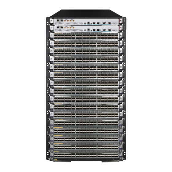
Page 8: Chassis Components
Figure 1-2 S12508R Figure 1-3 S12504R Chassis components The device has an MPU section, service module section, power module section, fan tray section, and fabric module section. The following figure uses the S12516R for illustration. - Page 9 Figure 1-4 Front and rear views of the S12516R (1) MPU section (2) Service module section (3) Power module section (4) Fan tray section (5) Fabric module section Table 1-1 Description for the device sections Section Description MPU section • (S12516R and S12508R—Ejector levers No MPUs are provided with the device.
- Page 10 Section Description No power modules are provided with the device. Purchase power modules yourself. • S12516R—16 power module slots, with eight on each side of the chassis rear. • S12508R—8 power module slots, with four on each side of the chassis rear. •...
-
Page 11: Technical Specifications
Technical specifications Weights and dimensions The device uses modular design. Its weight includes the chassis (including mounting brackets and filler panels) and its removable components. Table 1-3 Chassis weights and dimensions Model Weight Height Width Depth S12516R 86.1 kg (189.81 lb) 931 mm (36.65 in)/21 RU 440 mm (17.32 in) 857 mm (33.74 in) - Page 12 NOTE: Module dimensions are expressed as follows: • Height—Height of the front panel of the module. • Width—Width of the front panel of the module. • Depth—Depth from the front panel of the module to the connector (Including the connector, but excluding the ejector levers and captive screws).
-
Page 13: Module Power Consumption And System Power Consumption
Module power consumption and system power consumption Module power consumption The power consumption varies by module model and state. Table 1-8 shows the power consumption for different module models. • The static power consumption of a module refers to the power consumed by the module when module is running but all ports on the module are down and when no transceiver module is available on the optical interface of the module. -
Page 14: Heat Dissipation
Operating Non-operating Temperature 0°C to 40°C (32°F to 104°F) –40°C to +70°C (–40°F to +158°F) Relative humidity 5% to 95% 5% to 95% (noncondensing) Chassis ordering information To purchase an S12500R chassis, contact the sales agent or H3C sales personnel. - Page 15 Table 1-11 S12500R chassis ordering information Product code Product name Description 0235A2FL S12516R H3C S12516R Ethernet switch router chassis 0235A2FN S12508R H3C S12508R Ethernet switch router chassis 0235A2FM S12504R H3C S12504R Ethernet switch router chassis...
- Page 16 Contents 2 FRUs and compatibility matrixes ······························································ 2-1 MPUs ······························································································································································ 2-1 Service modules·············································································································································· 2-2 Fabric modules················································································································································ 2-3 Fabric module slot filler panels························································································································ 2-4 Slide rails························································································································································· 2-4 Power modules ··············································································································································· 2-4 Fan trays ························································································································································· 2-6 DC power cords ·············································································································································· 2-7 AC power cords··············································································································································· 2-7 Chassis component ordering information ·······································································································...
-
Page 17: Frus And Compatibility Matrixes
FRUs and compatibility matrixes For the compatible transceiver modules or cables of cards, see H3C S12500R Switch Series Cards and Transceiver Modules Compatibility Matrixes. MPUs You can install one MPU, or two MPUs for redundancy on the device. Do not install MPUs of different models on the same device. -
Page 18: Service Modules
Service modules Table 2-3 describes the interface modules available for the device. The interface modules provide different types and numbers of ports. IMPORTANT: To use the LSXM1CGQ36HBR1 or LSXM1CGQ36HFR1 interface modules on the device, choose high-performance fan trays for the device. See Table 2-12 for information about the available high-performance fan trays. -
Page 19: Fabric Modules
Interface Port Available transceiver Description Connector Port speed module quantity modules and cables model • QSFP28 transceiver modules 6-port • QSFP28 copper 100GBASE • QSFP28 cables Ethernet port: • optical QSFP28 fiber cables 100/40 interface • • QSFP+ transceiver LSXM1CGQ Gbps (QSFP28)/12- •... -
Page 20: Fabric Module Slot Filler Panels
Fabric module slot filler panels The device comes with empty fabric module slots. For good ventilation, purchase and install filler panels in the empty fabric module slots. Table 2-5 Fabric module slot filler panels Item Quantity per chassis S12516R fabric module slot filler panel 0 to 4 S12508R fabric module slot filler panel 0 to 4... - Page 21 Table 2-7 Power modules available for the device Device model Available power modules PSR2400-54A S12516R PSR2400-54D S12508R PSR3000-54A S12504R PSR3000-54AHD Table 2-8 PSR2400-54A power module specifications Item Specifications Rated input voltage 100 to 240 VAC @ 50 or 60 Hz Rated output voltage 54 VDC Maximum input current...
-
Page 22: Fan Trays
Item Specifications Operating temperature –10°C to +50°C (–14°F to +122°F) Ambient temperature Storage temperature –40°C to +70°C (–40°F to +158°F) Table 2-11 PSR3000-54AHD power module specifications Item Specifications Rate input voltage 100 to 240 VAC @ 50 or 60 Hz AC input Maximum input current 20 A... -
Page 23: Dc Power Cords
Select 16A AC power cords for the device. For the connector types of different countries or regions, see H3C Power Cords & Cables User Guide. Chassis component ordering information To purchase chassis components, contact the sales agent or H3C sales personnel. Table 2-14 Chassis component ordering information Product code Product name Description... - Page 24 Fan module for the H3C S12508R 0231A2X9 LSXM104XFAN Fan module for the H3C S12504R 0231A4WX LSXM116XFANH High speed fan module for the H3C S12516R 0231A4X0 LSXM108XFANH High speed fan module for the H3C S12508R 0231A4X1 LSXM104XFANH High speed fan module for the H3C S12504R...
- Page 25 Contents 3 LEDs ········································································································ 3-1 MPU LEDs ······················································································································································ 3-1 Management Ethernet port LEDs············································································································ 3-1 Fan tray status LEDs ······························································································································· 3-2 Power module status LEDs ····················································································································· 3-2 Module status LEDs ································································································································ 3-3 MPU active/standby status LED ·············································································································· 3-3 Service module LEDs······································································································································ 3-3 SFP+ port LEDs ······································································································································...
-
Page 26: Leds
LEDs The device components provide various LEDs to indicate the component operating status. Table 3-1 LEDs at a glance LEDs LEDs: • Management Ethernet port LEDs • Fan tray status LEDs • Power module status LEDs • Module status LEDs •... -
Page 27: Fan Tray Status Leds
For the description of the pair of LEDs, see Table 3-2. Table 3-2 Description for the pair of LEDs for a 10/100/1000BASE-T management Ethernet port LINK Description A link is present, and the management Ethernet port is receiving Flashing or sending data. A link is present. -
Page 28: Module Status Leds
Module status LEDs An MPU provides one status LED for each module. For the description of the LED, see Table 3-6. NOTE: The MPU and service module slot numbers are marked on the ejector lever pillow blocks at the left and right sides of the slots. -
Page 29: Qsfp+ Port Leds
LED status Description Green A link is present. The SFP+ port is operating at 10 Gbps. Orange A link is present. The SFP+ port is operating at 1000 Mbps. No link is present. QSFP+ port LEDs A LED is provided for each QSFP+ port to indicate the link status and data receiving/transmitting status of the QSFP+ ports. -
Page 30: Fabric Module Status Leds On A Fan Tray
LED status Description No power is provided to the fabric module or the fabric module has not started loading software. Fabric module status LEDs on a fan tray A fan tray provides a LED pair for each fabric module it covers. •... -
Page 31: Fan Tray Leds
Table 3-12 Description for fabric module status LEDs on a fan tray Description Flashing (once per The fabric module is operating correctly. second) The fabric module has failed. • The fabric module is loading software. Flashing (once per • The fabric module is operating incorrectly. For example, the second) temperature exceeds the acceptable range. - Page 32 Status Description PSR2400-54D • No power is being input. • The power module is in self-protection state because of low INPUT OK input voltage. Green Power is being input correctly. Green Power is being output correctly. The power module is in self-protection state because of one of the following problems: •...
- Page 33 Contents 4 Cables ····································································································· 4-1 Console cable ················································································································································· 4-1 Ethernet twisted pair cable ······························································································································ 4-2 RJ-45 connector ······································································································································ 4-2 Cable pinouts ·········································································································································· 4-2 Cable type ··············································································································································· 4-2 Pin assignments ······································································································································ 4-4 Making an Ethernet twisted pair cable ···································································································· 4-5 Optical fiber ····················································································································································· 4-5 Optical fiber ·············································································································································...
-
Page 34: Cables
Cables This chapter describes cables used for connecting network ports. Table 4-1 Cable description Cable Port type Application RJ-45 Ethernet port at one Connects the console port of the device to Console cable end and DB-9 port at the the console terminal other end Connects RJ-45 Ethernet ports to transmit Ethernet twisted pair cable... -
Page 35: Ethernet Twisted Pair Cable
RJ-45 Signal DB-9 Signal Ethernet twisted pair cable An Ethernet twisted pair cable consists of four pairs of insulated wires twisted together. It mainly transmits analog signals and is advantageous in transmitting data over shorter distances. The maximum transmission distance is 100 m (328.08 ft). RJ-45 connector An Ethernet twisted pair cable connects network devices through the RJ-45 connectors at the two ends. - Page 36 Type Description Category 6 Transmits data at a speed higher than 1 Gbps, with a bandwidth of 250 MHz. Category 6A Transmits data at a speed higher than 10 Gbps, with a bandwidth of 500 MHz. Category 7 Transmits data at a speed higher than 10 Gbps, with a bandwidth of 600 MHz. Based on pinouts Ethernet twisted pair cables can be classified into straight through and crossover cables based on their pinouts.
-
Page 37: Pin Assignments
Figure 4-4 Crossover cable white/orange orange white/green blue white/blue green white/brown brown Crossover cable white/green green white/orange blue white/blue orange white/brown brown Pin assignments Select an Ethernet twisted pair cable according to the RJ-45 Ethernet port type on your device. An RJ-45 Ethernet port can be MDI (on routers and PCs) or MDIX (on the device). -
Page 38: Making An Ethernet Twisted Pair Cable
10Base-T/100Base-TX 1000Base-T Signal Function Signal Function Send data BIDA+ Bi-directional data cable A+ Reserved BIDD+ Bi-directional data cable D+ Reserved BIDD- Bi-directional data cable D- Send data BIDA- Bi-directional data cable A- Reserved BIDC+ Bi-directional data cable C+ Reserved BIDC- Bi-directional data cable C- To ensure normal communication, the pins for sending data on one port should correspond to the pins for receiving data on the peer port. -
Page 39: Optical Fiber Cable
• Single mode fiber—It has a core size of 10 µm or smaller, and has a lower modal dispersion. It carries only a single ray of light. It is mostly used for communication over longer distances. • Multi-mode fiber—It has a core size of 50 µm or 62.5 µm or higher, and has a higher modal dispersion than single-mode optical fiber. -
Page 40: Precautions
Figure 4-5 MPO connector Figure 4-6 LC connector Precautions • Make sure the fiber connector and fiber type match the transceiver module type. • The fiber ports on the device are provided with dust plugs. Insert the dust plugs into the fiber ports that you are not to use, to prevent particles from entering the ports. -
Page 41: Qsfp+ Copper Cable
Figure 4-7 SFP+ copper cable (1) Connector (2) Pull latch QSFP+ copper cable You can use QSFP+ copper cables to connect the QSFP+ ports. Figure 4-8 QSFP+ copper cable (1) Connector (2) Pull latch QSFP28 copper cable You can use QSFP28 copper cables to connect the QSFP28 ports. Figure 4-9 QSFP28 copper cable (1) Connector (2) Pull latch... -
Page 42: Qsfp+ To Sfp+ Copper Cable
QSFP+ to SFP+ copper cable A QSFP+ to SFP+ copper cable is a cable with one QSFP+ module at one end and four SFP+ modules at the other end. Figure 4-10 QSFP+ to SFP+ copper cable (1) QSFP+ connector (2) QSFP+ pull latch (3) SFP+ connector (4) SFP+ pull latch...
Need help?
Do you have a question about the S12500R Series and is the answer not in the manual?
Questions and answers