Table of Contents
Advertisement
Quick Links
Solid State Logic
S O U N D | | V I S I O N
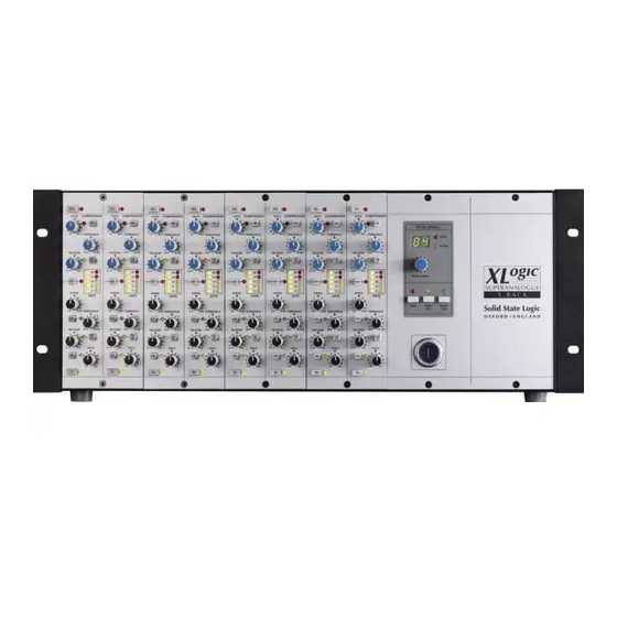
SUPERANALOGUE
X R A C K
Super-Analogue™ Outboard
X-Rack E Series EQ User's Guide
This documentation package contains the User's Guide for your new X-Rack E Series
EQ module. Depending on the age of your X-Rack, these pages may already be present
in your X-Rack Owner's Manual – please check to see if these pages match your
Manual. If they do not, these pages should be filed alongside it.
Please Note. For correct operation of this module, your X-Rack unit must be running V1.4/2 or later
software. Please refer to your X-Rack Owners Manual for instructions on how to check the
current software version and how to obtain and install a newer version if required.
There may be a newer version of the X-Rack Owner's Manual available for download from our
website (www.solid-state-logic.com)
82S6XR0K0A
Advertisement
Table of Contents

Related Manuals for Solid State Logic Super-Analogue Outboard X-Rack E Series


Summary of Contents for Solid State Logic Super-Analogue Outboard X-Rack E Series
- Page 1 Solid State Logic S O U N D | | V I S I O N SUPERANALOGUE X R A C K Super-Analogue™ Outboard X-Rack E Series EQ User’s Guide This documentation package contains the User’s Guide for your new X-Rack E Series EQ module.
-
Page 3: Operation
X-Rack E Series EQ Module K. E Series EQ Module K.1 Connection The module input and output gains can be set to operate at a nominal level of either +4dBu or –10dBV, using a switch on the connector panel. To select the appropriate level for the equipment you are connecting to, please check the operating manual for your mixer or DAW. - Page 4 X-Rack Owner’s Manual Page K-2...
-
Page 5: Performance Specification
The following pages contain audio performance specification figures for the X-Rack E Series EQ Module. No other Solid State Logic products are covered by this document and the performance of other Solid State Logic products can not be inferred from the data contained herein. - Page 6 X-Rack Owner’s Manual K.3.4 Controls This is a four band equaliser that can be switched between two different sets of curves; one based on SSL’s ‘02’ (‘Brown Knob’) EQ and the other based on the latest version of the classic ‘242’ E Series (‘Black Knob’) HF Band controls: Frequency Variable from 1.5kHz to 16kHz...
-
Page 7: Calibration Information
X-Rack E Series EQ Module K.4 Calibration Information The X-Rack E Series EQ module is factory calibrated and should only need calibration if a potentiometer or other component has been replaced or if it is suspected that there is a problem with calibration. In each of the following instructions it is assumed that the lid of the X-Rack has been removed and that power has been applied. - Page 8 X-Rack Owner’s Manual 4. Switch BLK in and re-adjust LMF Frequency for maximum level. 5. Adjust VR16 for +18dBu ±0.25dB. 6. Reset LMF Gain to its centre indent position and release the BLK switch. Re-check the audio level meter for 0dBu. LF EQ –...
-
Page 9: Audio Output
X-Rack E Series EQ Module K.5 Connector Details Audio Input Audio Output Location: Rear Panel Location: Rear Panel Conn’ Type: XLR Female Conn’ Type: XLR Male Description Description Chassis Chassis Audio +ve Audio +ve Audio –ve Audio –ve K.6 Physical Specification Depth: 200mm / 7.9 inches including front panel knobs, excluding connectors... - Page 10 X-Rack Owner’s Manual Page K-8...
Need help?
Do you have a question about the Super-Analogue Outboard X-Rack E Series and is the answer not in the manual?
Questions and answers