
Related Manuals for Contec ADI16-4(USB)


Summary of Contents for Contec ADI16-4(USB)
- Page 1 PC-HELPER Isolated High-Resolute Analog Input Module for USB2.0 ADI16-4(USB) User’s Guide CONTEC CO., LTD.
-
Page 2: Check Your Package
Check Your Package Thank you for purchasing the CONTEC product. The product consists of the items listed below. Check, with the following list, that your package is complete. If you discover damaged or missing items, contact your retailer. Product Configuration List - USB module [ADI16-4(USB)] …1... -
Page 3: Copyright
No part of this document may be copied or reproduced in any form by any means without prior written consent of CONTEC CO., LTD. CONTEC CO., LTD. makes no commitment to update or keep current the information contained in this document. The information in this document is subject to change without notice. -
Page 4: Table Of Contents
Table of Contents Check Your Package ............................ i Copyright ..............................ii Trademarks ..............................ii Table of Contents ............................iii INTRODUCTION Summary ..............................1 Features ..............................1 Support Software ..........................2 Accessories (Option) ........................... 2 Customer Support ............................3 Web Site..............................3 Limited One-Year Warranty ........................ - Page 5 Connecting to an External Device ......................20 Signal Layout ............................. 20 Connection Method ........................... 20 Sampling ..............................24 Input Range and Conversion Data....................24 Sampling Rate ............................ 25 Trigger ..............................26 Connecting an External Power Supply ....................27 How to install the module......................... 29 Installation orientation........................
- Page 6 Hardware Specification..........................53 Software Specification ..........................55 Circuit Block Diagram ..........................56 Timing Chart .............................. 57 Physical dimensions ..........................58 APPENDIX Glossary..............................59 ADI16-4(USB)
- Page 7 ADI16-4(USB)
-
Page 8: Introduction
1. Introduction 1. Introduction Summary This product is a USB2.0 compatible terminal module that extends the analog input function of USB port of PCs. This product features 4ch 16-bit analog input and is isolated from the bus line to the PC. The signal lines can be connected directly to the terminals on this product. -
Page 9: Support Software
In addition, you can verify the operation of hardware using Diagnostic programs. For more details on the supported OS, applicable language and new information, please visit the CONTEC’s Web site. Accessories (Option) -
Page 10: Customer Support
You can download updated driver software and differential files as well as sample programs available in several languages. Note! For product information Contact your retailer if you have any technical question about a CONTEC product or need its price, delivery time, or estimate information. Limited One-Year Warranty CONTEC product is warranted by CONTEC Co., LTD. -
Page 11: Safety Precautions
1. Introduction Safety Precautions Understand the following definitions and precautions to use the product safely. Safety Information This document provides safety information using the following symbols to prevent accidents resulting in injury or death and the destruction of equipment and resources. Understand the meanings of these labels to operate the equipment safely. -
Page 12: Handling Precautions
It may cause a trouble in recognizing and operating the device according to the kind of USB hub. If you use the USB hub, we encourage you to take advantage of the CONTEC’s product loan service to confirm operation before purchasing. - Page 13 1. Introduction Regarding “EMC Instruction Class A Notice” This product has acquired the above-mentioned standard. However, a sufficient margin may not be secured for the standard. In this case, use a ferrite core (SEIWA E04SR301334 or a compatible product) for the USB cable and the power cable of this product, and use two ferrite cores it for the power cable of AC outlet side.
- Page 14 1. Introduction FCC PART 15Class A Notice NOTE This equipment has been tested and found to comply with the limits for a Class A digital device, pursuant to part 15 of the FCC Rules. These limits are designed to provide reasonable protection against harmful interference when the equipment is operated in commercial environment.
-
Page 15: Environment
1. Introduction Environment Use this product in the following environment. If used in an unauthorized environment, the board may overheat, malfunction, or cause a failure. Operating temperature 0 - 50°C Operating humidity 10 - 90%RH (No condensation) Corrosive gases None Floating dust particles Not to be excessive Inspection... -
Page 16: Module Nomenclature
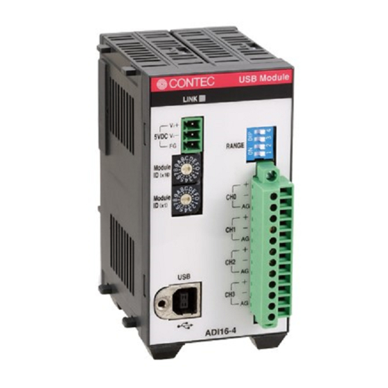
2. Module Nomenclature 2. Module Nomenclature Figures 2.1 shows the names of module components. In the figures, the indicated switch settings represent factory settings. LINK Status LED +5VDC Input Range setting SW Module ID Analog Input CH0 - CH3 USB Port Figure 2.1. - Page 17 2. Module Nomenclature ADI16-4(USB)
-
Page 18: Setup
3. Setup 3. Setup Connection-Overall Diagram This is connection-overall diagram. Please reference to this page for actual Connecting to an External Connecting to a PC Device (Page 20) (Page 16) Software Installation (Page 13) Connecting with Expansion Accessories (Page 45) Device RANGE Mounting on a DIN Rail... -
Page 19: Range Setting Switches
3. Setup Range Setting Switches Inputs can be set as voltage or current inputs to suit your requirements. A single input range applies for all channels and separate ranges cannot be set for each channel. Do not set other the specified settings. Setup method The voltage/current input setting is set using a DIP switch on the module's panel. -
Page 20: Setup Flow
3. Setup Setup Flow The following shows the basic flow for installing USB module. Software Installation Setting Properties Connecting to a PC -API-USBP(WDM) Using Device Manager -Installing USB driver Development -Setting device name Environment -Utilities Page 13 Page 16 Page 18 Software Installation Install software. -
Page 21: Installation Of Api-Usbp(Wdm) Development Environment
3. Setup Installation of API-USBP(WDM) Development Environment Installation of development environment is namely installing supplied online help and sample program in all language in order to use API function. Step1 Clicking on “Install Development or Execution Environment” [API-USBP(WDM) Installer] dialog box displays. Step2 Selecting “Advanced Analog I/O driver”... -
Page 22: Installing The Utility
3. Setup Installing the Utility The utility is application with which you can verify device operation easily. Run the “X:\ USBP_UTILITY\ ENG\ DioMnt\ setup.exe (X:CD-ROM drive)” from the [Run] of start menu. Follow the instructions that appear on the screen. This completes the installation. ADI16-4(USB) -
Page 23: Connecting To A Pc
It may cause a trouble in recognizing and operating the device according to the kind of USB hub. If you use the USB hub, we encourage you to take advantage of the CONTEC’s product loan service to confirm operation before purchasing. - Page 24 3. Setup Step3 Starting “Found New Hardware Wizard” Start “Found New Hardware Wizard”, then select “Install from a list or specific location[Advanced]” item and finally click on “Next” button. In Windows Vista, Because the driver's installation is completed by "Installing the Software", it is not necessary to operate it about the Hardware Wizard.
-
Page 25: Setting Properties Using Device Manager
Right-click on [My Computer] and select [Properties] to start device manager. * The model number of the USB module appears under CONTEC Devices [XXXXX]. In the case of Windows XP/2000 From [Start] menu, click on [Settings]-[Control Panel]-[System] and then click on [Device Manager] button in [Hardware] tab. - Page 26 3. Setup Step2 Setting the Device Name Right-clicking on USB module name and selecting [Properties] displays [USB Module Properties]. Open [Common Settings] tab and enter arbitrary name in the editing box for device name. (Default name also can be used.) CAUTION USB driver can not be used without settings.
-
Page 27: Connecting To An External Device
3. Setup Connecting to an External Device Signal Layout The Module can be connected to an external device using a 12-pin (1 group) connector that is provided on the Module face. CH0 [+] Analog Input 0ch [+] CH0 [-] Analog Input 0ch [-] Analog Ground CH1 [+] Analog Input 1ch [+]... - Page 28 3. Setup Making a connection using the differential input format This is a method of measuring the voltage of signal source by connecting the 3 wires (2 signal wires- plus input pin[+] and minus input pin[-], analog ground[AG]) of the module. How to connect: Connect the analog ground to the signal source ground.
- Page 29 3. Setup Measuring voltage Set the range setting switch and software setting to voltage input. Voltage Input RANGE Figure 3.8. Setting the voltage input The figure below shows an example of using flat cable to connect a reference voltage generator. As a two-wire connection is used when measuring a device such as a battery that only has positive and negative terminals, connect the negative terminal to CH0 (-) and AG.
- Page 30 3. Setup Measuring current Set the range setting switch and software setting to current input. Current Input RANG Figure 3.9. Setting the voltage input The following figure shows an example of flat or shielded cable connection. The figure below shows an example connection using a flat cable. Connect the positive terminal of the current source to the channel's [+] input and the negative terminal to the [-] input.
-
Page 31: Sampling
3. Setup Sampling Input Range and Conversion Data On ADI16-4(USB), the range of input can be selected from ±10V ⋅ 0 – 20 mA by using software. The analog signals are converted into digital signals with a 16-bit resolution based on the range setting. Current Input As for this module, 0 –... -
Page 32: Sampling Rate
3. Setup Sampling Rate A/D Conversion Timing The conversion time for the A/D converter in the ADI16-4(USB) is 10 µ sec for voltage measurement and 40 µ sec for current measurement, and the total time required to convert each analog input signal to digital data is (number of channels) x 10 µ... -
Page 33: Trigger
3. Setup Trigger The condition making ADI16-4(USB) start or stop the converting. The converting can be controlled by software and the data of analog input. CAUTION When using multiple ADI16-4(USB), the modules don’t synchronize. Software trigger The converting can be started or be stopped by software. Start Stop Start command... -
Page 34: Connecting An External Power Supply
3. Setup Connecting an External Power Supply This module must be connected with an external power supply (in a self-powered state). Connect the external power supply to the +5 VDC input terminal. Power supply (5V) Power supply (GND) 5VDC Frame ground Figure 3.10. - Page 35 3. Setup 2 Output POWER 5VDC 5VDC 85-132VAC AC Input AC(N) MC1,5/3-ST-3,5 AC(L) (Phoenix Contact) POW-AD13 POWER 5VDC DC Input 10*30VDC POW-DD10 Figure 3.12. Optional power supply For the power supply for installation on a DIN rail, use the connector MC1,5/3-ST-3,5 (Phoenix Contact).
-
Page 36: How To Install The Module
3. Setup How to install the module Installation orientation Please use the module following orientation illustrated in the graph when the module is mounting on a DIN rail and being used on a desk. It should be noted that lateral slit of the module being covered brings about malfunction. -
Page 37: Mounting With Magnets
3. Setup Mounting with magnets Two magnets are appended to this product. It is easy of attachment and removal of the module to metal sides, such as a desk, partition panel and so on. Initial adhesion strength of seal is high, but adhesion strength decreases an ability of peeling strength if once removing a magnet from the enclosure of USB module. -
Page 38: Mounting On A Din Rail
3. Setup Mounting on a DIN Rail Installation Method The following illustrates the installation with expansion module. Please reference to page 45, “6. Connecting with Expansion Accessories”. (1) Pushing the fixing hook with a flat-head screwdriver renders it into a lock-enabled condition (this should be done on all connected modules). - Page 39 3. Setup (3) The fixing hook is automatically locked, and the module can be mounted in one-touch. Side view Fixing hook Figure 3.16. Mounting on a DIN Rail < 3 / 3 > Removal method CAUTION Any operation involving the disconnection of modules in a unit (in which multiple modules are connected) that is attached to a DIN rail should be performed after the unit is removed from the DIN rail.
- Page 40 3. Setup (2) With the fixing hook unlocked, pull the lower part of the unit toward you. Side view Figure 3.17. Removing the Module from the DIN Rail < 2 / 3 > (3) By lifting the unit, you can easily remove it from the DIN rail. Side view Figure 3.17.
-
Page 41: Using Several Modules With The Same Model
3. Setup Using Several Modules with the same Model Each module should be assigned a unique Module ID in order to let USB driver recognize them when several modules of the same model are being used. Factory settings (=00) can be used when only one module is connected to one computer. Unnecessary to set Module ID Stand alone Expansion module being used. -
Page 42: Application Development
4. Application Development Please reference to online help and sample program when developing applications. Reference to Online Help Click on [Programs]-[CONTEC API-USBP(WDM)]-[API-USBP(W32) Help] from [Start] menu. The information for application development, such as function reference is provided in [API- USBP(W32) Help]. -
Page 43: Sample Program
4. Application Development Sample Program Sample programs are copied in installation path. (The default path is Program Files\CONTEC~) Sample programs in all language are provided here. To run a sample program, click on [Programs]- [CONTEC API-USBP(WDM)]- [AIO]-[Sample Name] from [Start] menu. -
Page 44: Troubleshooting
5. Troubleshooting 5. Troubleshooting When encountering trouble or question, you should reference to this section first. For the usage of [API Function Library], please reference to online help or the sample program. If you cannot find any piece of applicable information here or taking a suggested action does not solve the problem, contact your retailer. -
Page 45: Q&A
5. Troubleshooting Q&A Question Answer Can it run on Windows NT4.0 or Windows 95? In addition, it can not run on Windows 3.1, Windows NT3.51 and so on. Can it run on OS different It can not run on non-Windows OS such as Linux, MS-DOS etc. from Windows? Can you make an USB Not support. - Page 46 Run diagnostic program and [Diagnosis ...] to get the version of the driver. USB driver? How to upgrade USB driver You can download it from following homepage when there is latest edition. to latest edition? http://www.contec.com/download How to start the device Windows 2000/XP: manager? Start Start->Settings->Control Panel->System.Select Hardware and click on Device Manager.
-
Page 47: Diagnostic Program
5. Troubleshooting Diagnostic Program Running diagnostic program may identify that if abnormality exists in hardware or software. Run diagnostic program, open Properties for USB module of device manager and then click on [Diagnosis] button in [Common Settings] tab. Using Diagnostic program, you can not only verify the status of current input but also perform further diagnosis by clicking on... -
Page 48: Version Upgrade
Step3 Connecting USB Module with USB Port Please connect USB port after AC adapter has been connected when using self power. Step4 Starting Firmware Upgrade Tools Click on [Programs]-[ CONTEC API- USBP(WDM)]-[Firmware upgrade tool] from [Start] menu. Step5 Specifying Upgrade File Clicking on [Browse] button specifies the file which has been downloaded. -
Page 49: Driver Upgrade
Driver Upgrade If there is up-to-date driver, it is supplied in the homepage of our company. https://www.contec.com/ Returning to Initial State This is the method of returning to initial state. It is suggested that you should return to initial state and perform installation again when the operation is losing stabilization. - Page 50 [Device Manager] tab. (You can also open Device Manager by right clicking on My Computer and selecting Properties.) 2. All of the hardware that uses the API-TOOL(WDM) driver is registered under the CONTEC Devices tree. Open the device tree, select the hardware to uninstall, and then right-click the hardware.
- Page 51 <Uninstall of device driver> Use [My Computer] - [Control Panel] - [Add and Remove Programs] to uninstall the device driver. Select [Windows driver package - CONTEC (****)] and then click [Change/Remove]. * "***" contains the driver category name (caio, ccnt, cdio, csmc, etc.).
- Page 52 <Uninstall of development environment> Use [My Computer] - [Control Panel] - [Add and Remove Programs] to uninstall the development environment. Select [CONTEC API-***(WDM) VerX.XX (development environment)] and then click [Add/Remove]. * "***" contains the driver category name (AIO, CNT, DIO, etc.).
- Page 53 5. Troubleshooting ADI16-4(USB)
-
Page 54: Connecting With Expansion Accessories
6. Connecting with Expansion Accessories 6. Connecting with Expansion Accessories When lacking of analog input channel used to connecting external device, you have to purchase a new same module, and thus it not only increases cost but also doubles installation space. At the same time, adding channels is considered when designing this module, and additional module can be connected by the connector on module side, so that not only the cost but also the installation space is controlled. -
Page 55: Setting A Device Id
6. Connecting with Expansion Accessories Setting a Device ID Set Device ID by rotary switch on the front when adding modules. The ID for the first module being added must be 1 and values 2 and 3 are for the following two modules respectively. -
Page 56: Connection Between Modules
6. Connecting with Expansion Accessories Connection between Modules Stack Connection Locking Devices The module contains connecting locking devices ( mark, two units at the top and bottom). Locking device Stacking hook Figure 6.3. Stack Connection Locking Devices ADI16-4(USB) -
Page 57: How The Stack Connection Locking Device Works
6. Connecting with Expansion Accessories How the Stack Connection Locking Device Works Locking Unlocking Push the pawl of the locking device with a tool Push the groove of the locking device with a tool that has a slender tip downward from above to that has a slender tip in the direction of the arrow open the spring for the locking device (the groove until the device is locked. -
Page 58: Connecting The Module
6. Connecting with Expansion Accessories Connecting the Module Inserting the stack hook by aligning it with the hook insertion inlet for the other device automatically locks the module. (If a stack connector protective cover is attached, the connection operation should be performed after the cover is removed.) Figure 6.5. - Page 59 6. Connecting with Expansion Accessories ADI16-4(USB)
-
Page 60: Product Specification
7. Product Specification 7. Product Specification Hardware Specification Table 7.1 lists the hardware specification of ADI16-4(USB). Table 7.1. Hardware Specification < 1 / 2 > Item Specification Analog input Input format Bus-isolated voltage / current input Voltage: Bipolar ±10V Input range Current: 0 - 20mA Voltage: ±20V Maximum input rating... - Page 61 7. Product Specification Converting speed of A/D converter. The minimum executable sampling period is depending on internal processing time and is about 200µsec (using one channel) - 1msec (using 16 channels). (Measured values: The period may be longer due to factors such as the load on the USB link.) It takes the unit of 1000msec (1000msec, 2000msec, 3000msec, ...) when expansion module being used.
-
Page 62: Software Specification
7. Product Specification Software Specification Table 7.3. Windows Driver Specification Item Specification Support OS <64 bit OS> Microsoft Windows 7 x64 Edition Microsoft Windows Server 2008 x64 Edition Microsoft Windows Vista x64 Edition Microsoft Windows Server 2003 x64 Edition Microsoft Windows XP Professional x64 Edition <32 bit OS>... -
Page 63: Circuit Block Diagram
7. Product Specification Circuit Block Diagram +5V D+ D- GND USB Connector Flash Module ID DRAM (2MB) (512KB) Micro USB Connector Processor Device ID A/D Converter Control Circuit Instrument Isolator Amplifier 4-channel Multiplexer DC/DC with Voltage Converter Protection Interface Connector CH0 to CH3 Figure 7.1. -
Page 64: Timing Chart
7. Product Specification Timing Chart Sampling timer Data input C1 + C2 C1 + C2 Device A/D conversion A/D conversion ID=0(module) ID=1(expansion) Processing [C1]: 20µsec [C2]: Voltage input 10µsec / Current input 40µsec Figure 7.2. Timing Chart Setting 1000 µ sec Sampling timer value: Modules used: ADI16-4(USB) -
Page 65: Physical Dimensions
7. Product Specification Physical dimensions (1.2) (1.2) 50.4 64.7 [mm] * shows the center position of DIN rail. ( ) shows the referring dimension. Figure 7.3. Physical dimensions of the USB module Figure 7.4. Physical dimensions of attached AC adapter (POA200-20-2) ADI16-4(USB) -
Page 66: Appendix
8. Appendix 8. Appendix Glossary The glossary contains a brief description of terms used in this manual. Terms Explanation It is abbreviation for Application Program Interface. [Application Program It is the open program interface for OS corresponding to applications, and all Interface] application processing are basically performed through the API. - Page 67 CONTEC CO., LTD. December 2017 Edition 3-9-31, Himesato, Nishiyodogawa-ku, Osaka 555-0025, Japan https://www.contec.com/ No part of this document may be copied or reproduced in any form by any means without prior written consent of CONTEC CO., LTD. [12152017] [03242005] Management No. NA05940 [12152017_rev11] Parts No.
Need help?
Do you have a question about the ADI16-4(USB) and is the answer not in the manual?
Questions and answers